Abstract
This research work introduces the concept of “useful arc power” and the thermal model, first introduced by Dittmer and Krüger, to establish the arc length at any stage of the heat in Alternate Current Electric Arc Furnaces (AC-EAF), based on the estimation of the fraction of the energy transferred to the metallic load by radiation. Radiation is the most effective way to transfer heat in an arc furnace in presence of metallic scrap (bore-in and early meltdown). On the other hand, if the arc is not adequately covered with slag, radiation is extremely dangerous to the furnace integrity. When the furnace is fully loaded, scrap protects the walls and cooling panels and then arc radiation must be maximized. To increase energy efficiency, and at the same time reduce circuit power losses, the arc length should be controlled. However, arc instability prevents to increase radiation, as desired, and a compromise must be reached between arc length and arc stability. In this work AC-EAF electric circuit is modeled and analyzed under different heat stages. Electrodes, anode and cathode, fall regions can be considered as energy losses and their associated power may be deducted for the estimation of the “useful arc power” and for the definition of the operational currents in the heat process, particularly during flat bath conditions (late meltdown and refining). As a result of the present study it is proved that current setpoints play an important role for energy saving at any stage of the heat. Finally, experimental results obtained from an industrial steel factory validate this approach to optimize the electrical energy consumption per ton of liquid steel in AC-EAF.
1. Introduction
Electric Arc Furnaces (EAF) are relevant to study because they contribute to 1/3 of the total world´s steel production and even small improvements in its energy efficiency could represent significant savings. EAFs are thermo-processing units using plasma arcs as heat sources capable of melting scrap or direct reduced iron (DRI) through the heat transfer mechanisms of conduction, convection and radiation. In the last two decades an increase in productivity of the furnace and a reduction in the electrode consumption were associated to the use of higher transformer’s tap voltages and lower electrode currents. These benefits may be explained by the implementation of two technological improvements in EAFs: 1) a higher capacity of the furnace cooling systems to extract heat and 2) foamy slag practices.1,2,3)
The precise modeling of the three asymmetrical arcs with process-dependent, nonlinear characteristics of the variable arc resistance and reactance is complicated because of the highly dynamical changes in the meltdown/heating process. Particularly the electrical parameters like voltages and current fluctuate with the dynamic behavior of the arc. Ryff and Bulav13) proposed methodologies to determine the short circuit impedances test that is very relevant to find the circuit parameters. To determine the proper selection of transformer tap, and current setpoint, Timm14) proposed electrical engineering circuit analysis based on simplified power locus diagrams for the study of the active and reactive power at the EAF. The effect of the operational reactance was studied by Köhle,5) he also analyzed the effect of the high reactance in the high voltage AC arc furnaces explaining the convenience to operate at higher arc resistances thus higher arc impedances.
A complete mathematical modeling of the electric arc furnace is proposed by Logar et al.,12) that integrates relevant concepts like the Cassie-Mayr modeling with the arc reactance model proposed by Köhle and also incorporating a function adding chaotic behavior to the voltage-current relation of the arc, their research work reproduces in a very accurate way the real furnace data. Electric arcs have been modeled by means of numerical modeling by Bakken, Gu & Larsen.15) Guo & Irons8) presented a research work estimating the radiation intensity of the AC arcs in an EAF using Computational Fluid Dynamic (CFD) methods. The electric arcs has been also modeled by means of the channel arc model applied by Sánchez, Ramírez & Conejo7) to estimate the power delivery by the arc to the heat transfer mechanism of radiation, convection and conduction.
The EAF optimization problem from has been mainly addressed with intelligent control techniques or by softcomputing techniques combined with analytical models. Staib17) proposed in 1992 the “Intelligent Arc Furnace (IAF™)” based on Artificial Neural Networks (ANN). The EAF optimization with the ANN was also presented by Poppe et al.16) and by Sesselmann et al.18) In the system developed by Gerling et al.19) for Siemens AG called SIMELT®NEC uses a control strategy with a neural optimization control system that provides the dynamic corrections for the setpoint of the electrode control system, this implementation reported reduction in energy consumption by 15 kWh/t of liquid steel. Another case of study reporting specific electrical energy reduction was implemented at the Dalmine steel plant, Italy by Bianchi et al.20) showing benefit of reduction in specific electrical energy consumption by 11 kWh/t of liquid steel.
In this research work, the effects of both, the operational reactance and the power circuit losses are considered to determine, using classical AC circuit theory formulation, the initial current setpoins. Once having an initial estimation in the current setpoints, the theoretical arc thermal radiation model introduced by Dittmer & Krüger4) is applied to estimate the increment in arc length during melting in presence of scrap to increase the proportion of energy transferred by the arc radiation. Finally, some proportion of the electrodes anode and cathode fall regions and their associated power losses are considered to determine the peak arc during stable arc conditions.
2. Electric Arc Circuit
2.1. Power Curves and Circuit Losses
In AC-EAF, the power system is composed by a power transformer with variable tap, and sometimes a reactor connected in series at the primary side, to increase current stability. The three AC arcs burn between the bases of the electrodes arranged in a triangle and the bath, and while the arcs burn the electrodes wear down.1) Electrical arc is mainly controlled by an electrode control system. The objective of the arc regulation (current or impedance) is to control a desired voltage-current ratio for a given voltage tap. The selection of the current or impedance setpoint impacts the power transfer and EAF efficiency. The electric engineering analysis of the Alternate Current Electric Arc Furnaces (AC-EAF) allows to approximate analytical solutions for the power transferred to the arc and to estimate the power losses in the circuit. Figure 1 shows the electrical circuit from the infinite bus bar. The AC-EAF can be modeled considering several reactances and resistances. In Fig. 1, Xpri and Rpri represent the primary reactance and resistance; Xfce and Rfce represent the EAF transformer secondary side line reactance and resistance respectively, including cables, arms and electrodes. Xarc and Rarc are the arc reactance and resistance, while Vsupi is the RMS value of the line voltage.

Several relations can be obtained by a simple electrical circuit analysis: Eq. (1) shows the calculated three phase power circuit losses, Pels, based on the line losses; Eq. (2) allows to obtain the active power supplied to the EAF, PEAF, and Eq. (3) indicates the calculated three phase arc active power, Parc, by subtracting the total line losses from the EAF power.
|
P
els
=
I
1
2
R
eq1
+
I
2
2
R
eq2
+
I
3
2
R
eq3
| (1) |
|
P
EAF
=
∑
p=1
3
[
1
τ
∫
0
τ
v
p0
i
p
dt
]
| (2) |
|
P
arc
=
P
EAF
-
P
els
| (3) |
where
vp0 is the phase
p to ground instantaneous feeding voltage,
ip is the phase
p instantaneous line current,
Ip is the phase
p Root Mean Square (RMS) line current, and
Reqp is the furnace (line
p) equivalent resistance.
Power curves are useful to determine operational points in power for EAFs. Power curves help to find ranges in electrode current where the power may be maximized both at the arc Parc and at the transformer secondary side PEAF. Figure 2 shows EAF active, reactive and apparent power curves versus electrode (line) current for an EAF power system using a 120 MVA transformer in tap 8 (913V). The slight curvature of the apparent power is due to the voltage drop at the furnace impedances.
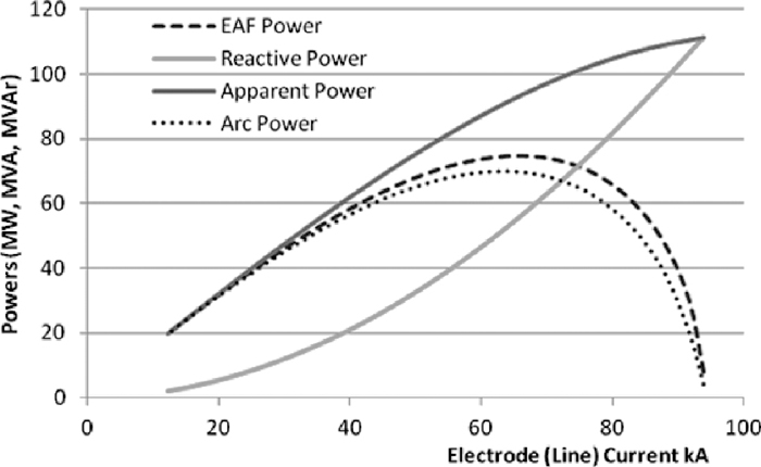
Since the arc volt-ampere characteristic is nonlinear, the entire electrical circuit becomes non-linear as well.3) The harmonic currents are produced when the harmonic voltages from the arc are imposed across the furnace transformer impedances. Power curves of Fig. 2 can be estimated for the supply frequency and considering typical values of source impedance. In practice, current values to obtain the peak power can’t be determined easily because of the chaotic arc behavior, particularly during initial bore-down and melting, and their values change constantly during the heat. For a complete analysis, harmonics of higher order than fundamental have to be considered since the harmonic distortion affects the active power and power factor.
Harmonic distortion is a practical indicator for arc stability; this stability term is used for process monitoring and control. An arc stability indicator has already been proposed,21) where the virtual-neutral to ground voltage measurements were found to be useful to determine arc conditions. Once unstable or stable arc conditions are detected, it is relevant to estimate the current setpoints to obtain the peak powers for these arc stability conditions and this is the main objective of the present work.
2.2. Peak Power and Current Settings
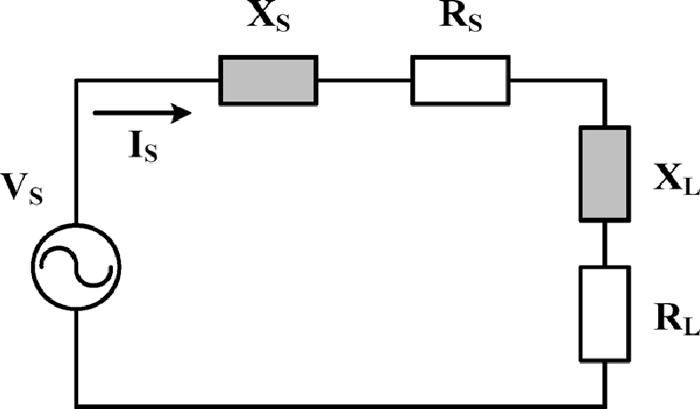
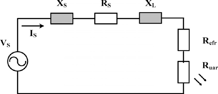
An expression for the maximum power delivered to the arc can be deduced using a simplified model of the secondary circuit of an EAF power transformer. In Fig. 3 the EAF electrical circuit can be thought as an ideal voltage source, VS, a combined resistor-reactor modeling the source resistances, RS, and reactances, XS, (cables, electrodes), and a non linear load RL and XL modeling the arc.
The circuit of Fig. 3 is expressed in terms of source and load elements for convenience of the analysis. The load reactance may not be attributed to the arc, but to the furnace, and the electric arcs as a load may be split in two terms corresponding to the arc regions, as it will be discussed later. The reactor parts in Fig. 3 is responsible for the displacement between the fundamental arc voltage and arc fundamental current, therefore the current in the circuit, IS, is given by Eq. (4), and the power delivered to the load (electric arc), PL, is given by Eq. (5).
|
I
S
=
V
S
(
R
S
+
R
L
)
+j(
X
S
+
X
L
)
| (4) |
|
P
L
=
|
I
S
|
2
⋅
R
L
=
|
V
S
|
2
(
R
S
+
R
L
)
2
+
(
X
S
+
X
L
)
2
⋅
R
L
| (5) |
To find the value of arc resistance that maximizes the power delivered to RL, classical calculus was used to estimate the value of RL that makes the partial derivative with respect to load resistance RL be equal to zero, Eq. (6), and the value of RL that yields the maximum power to the arc is given by Eq. (7).
|
∂
P
L
∂
R
L
=
[
(
R
S
+
R
L
)
2
+
(
X
S
+
X
L
)
2
]
|
V
S
|
2
-
|
V
S
|
2
R
L
[
2(
R
S
+
R
L
)
]
[
(
R
S
+
R
L
)
2
+
(
X
S
+
X
L
)
2
]
2
=0
| (6) |
|
R
L
=
R
S
2
+
(
X
S
+
X
L
)
2
| (7) |
The load resistance RL (in our case the electric arc resistance) has its peak value in power when its value is equal to the square root of the sum of the squared source resistance and the squared sum of source and load reactances. The above expression for load resistance is substituted in Eq. (5) to find the maximum power dissipated at the load, Ppeak (Eq. (8)). The same expression for RL solved in Eq. (7) can also be substituted into Eq. (4) to find the current value at which the maximum power transfer occurs, IP peak (Eq. (9)).
|
P
peak
=
|
V
S
|
2
2(
R
S
+
R
S
2
+
(
X
S
+
X
L
)
2
)
| (8) |
|
|
I
P peak
|=
V
S
2
(
R
S
+
R
S
2
+
(
X
S
+
X
L
)
2
)
2
| (9) |
As it can be analyzed in the above expressions, all the EAF circuit elements are relevant for the calculation of the peak arc power and also for determining the current magnitude and phase angle of the current value. Source resistance and reactance are values that can be obtained from a short circuit test and even though the source resistance is a low value (around 1/10 the source reactance), it affects the current value at which the peak arc power occurs in around 9% (lower current). The operational reactance is a key parameter, neglected in previous electrical engineering analysis of the EAF circuit; that increases in early melting due to the presence of higher harmonic distortion during unstable arc conditions. The consideration of the changes in the arc reactance under unstable and stable arc conditions is one contribution of this research work that proposes an approach to find more precisely the current setpoints to obtain peak powers. Since the source reactance (short circuit transformer and furnace impedances) can be considered almost constant values only under sinusoidal conditions, the variation in the operational reactance depends mainly on the load reactance, in this case the arc reactance. The increase in operational reactance is attributed to the electric arc but is not part of the electric arc as explained below. The inductance effect of the electric arc is low (electric arcs are modeled mainly as variable resistances), therefore variations in the load reactance may be attributed to electromagnetic effects in the scrap load and furnace shell caused by the huge currents in the electrodes and cables. Operational reactance is also increased even more by harmonic distortion.
3. Heat Transfer in Electric Arcs
3.1. Alternate Current Electric Arcs
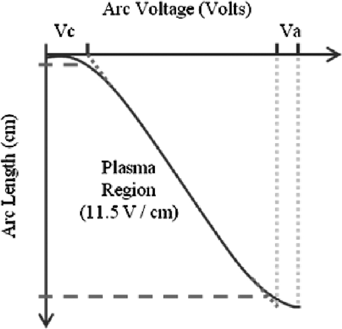
The arc discharge can be characterized in the following regions: the cathode fall, the arc column, and the anode fall. The voltage drop across the arc column (plasma region), which is relatively independent of current magnitude is approximately 11.5 Volts/cm.6) In AC arcs the fall regions voltages drops (anode and cathodes) are considered to be around 40 V.6) Therefore, arc voltage Varc keeps a directly proportional relation with the arc length larc as indicated in Eq. (10), where E is the voltage field of 11.5 Volts/cm and the constant 40 V is due to the voltage drops at the fall regions.
The voltage drop at the electrodes fall region has already been considered as a cathode resistance to get accurate results in modeling of AC-EAFs.12) As for the DC arcs the voltage drop at the electrodes fall regions is due to the work needed to extract and accelerate electrons from the electrode to the scrap or steel bath but in the AC arcs this function is in two directions, from cathodes to anodes when the electrode acts as cathode in half of the 50 or 60 Hz cycle, and from the steel/scrap to the graphite when the electrode acts as anode in the other semi-cycle of the alternating current. Figure 4 shows a characteristic curve of the cathode and anode voltages versus the arc length (this figure shows a case where an axial distance goes from the tip of the graphite electrode for the negative half-cycle of the AC arc). The figure shows voltage drops for the cathode and anode in small distances and a fairly constant voltage gradient for the arc column region.
3.2. Arc Thermal Radiation
According to computational fluid dynamics (CFD) simulations,7) the power dissipated by AC electric arc is transferred by three different mechanisms: by convection Pconv, by radiation Prad and by the electrons flow Pelec. Energy transferred by convection accounts for 70%, while the energy transferred by radiation is around 24% and the energy transferred by the flow of electrons, Pelec, represents only about 3% of the total energy transferred from the arc. The arc thermal radiation is relevant for the melting process, in particular in presence of scrap to melt inside the furnace. Once flat bath conditions are reached radiation is undesirable unless there is a good foamy slag covering the arc. Recent studies in theoretical estimation of the arc thermal radiation by Dittmer & Krüger,4) have proposed a refined estimation of the arc length for AC electric arcs based on experimental data. In this formulation the arc length, Eq. (11), depends on both arc voltage and arc current and, based on this arc length formula, a theoretical model for the arc thermal radiation has also been proposed by Dittmer & Krüger in Eq. (12).4)
|
P
rad
≈
(
V
arc
-80)
I
arc
8
| (12) |
These theoretical and experimentally fitted equations reproduce reasonable approximations for arc lengths of AC furnaces, if compared with the arc length estimated with Eq. (11). The estimation of the arc thermal radiation dissipated from the arc, Eq. (12), is around 30% of the total power delivered from the arc.
4. Theoretical Estimation of Useful Arc Power
4.1. Electrodes Fall Regions as Energy Losses
If the electric arcs are analyzed by regions, the useful power delivered by the electric arcs is the power dissipated at the plasma jet region and the power dissipated at the fall region (cathode or anode) that is in contact with the scrap or steel; the power dissipated at the electrodes fall regions (cathode or anode) is mainly transferred to the graphite electrodes and gases surrounding the electrodes. From Eq. (10) it can be noticed how the amount of arc voltage adding physical length to the arc and contributing to power dissipated at the plasma region is the term E·larc, while the other part of arc voltage, the voltage drop of 40 V, is related to generation of the electrons flow (work functions). In spite of simplicity, the voltage drop at the alternating anodes and cathodes of AC electric arcs, can be split in two and considered differently: The power in the fall region (anode or cathode) in contact with the scrap/steel is contributing to melt or heat, while the power at the electrodes fall regions (being anode or cathode) can be considered as heat losses. Therefore, the power losses at the “electrodes fall regions”, Pefr, can be calculated for all the three phases by means of Eq. (13).
|
P
efr
=
V
C
+
V
A
2
⋅(
I
1
+
I
2
+
I
3
)
=20⋅(
I
1
+
I
2
+
I
3
)
| (13) |
The power at the electrodes fall regions, needed to establish and to maintain the electric arcs, accounts for the significant amount of 20 kW per each kA of electrode current. Figure 5 shows our estimation of electrodes fall region losses from Eq. (13) and the power circuit (electrical) losses calculated by Eq. (1) and the addition of both. Line resistance is typically around a value of 0.4 mΩ (up to PCC), and cathode and anode voltages drops contributing to losses were considered 20 Volts. In Fig. 5 it can be seen how this here in proposed calculation of electrodes fall region losses are as comparable as the power circuit losses depending on the operational current.
4.2. Arc Power under Stable Arc Conditions
If the power at the electrodes fall regions is considered as heat loss, different arc power estimation can be computed. This, called here, “useful arc power”, is the power available to be transferred by the two main transfer mechanisms of radiation and convection at the plasma jet and by the conduction and heating of the region in contact with the scrap or metal. In practice some other losses are expected, particularly if the arc is not covered by either scrap or slag. The, “useful arc power”,
P
arc
*
, can be easily estimated by Eq. (14).
|
P
arc
*
=
P
EAF
-
P
els
-
P
efr
| (14) |
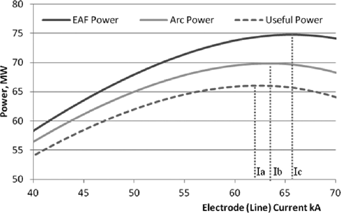
By using the previous analysis and Eqs. (13)–(14) derived in this work, it is possible to estimate the useful arc power for the different transformer taps o transformer-reactor tap combinations. Figure 6 shows the calculated useful arc power for a 120 MVA power transformer using tap voltage of 943 V (nominal current of 60 kA) and considering the following parameters: furnace impedance of 3.0 mΩ and furnace resistance 0.3 mΩ. Now there are three peak values of the corresponding power curves, point Ic, where the EAF transformer has its peak value, point Ib where the power delivery to the arc is maximum (arc power) and the new point, that represents the peak value of the useful arc power, this point Ia should be theoretically a more “energy efficient” operational point in current since it is found at a lower value of electrode current.
When the arc is very stable, in late melting or refine/heating, the longer arcs are not convenient anymore due to the large amount of slag needed to cover the arc or because the furnace is de-slag. In this scenario the operational current should be defined at the maximum “useful arc power” for a given tap. This useful arc power is obtained, by subtracting both power circuit losses and electrodes fall region losses from the measured power at the secondary side of the transformer. Going beyond this point will only increase losses. To consider the electrodes fall regions in the arc resistance modeling, the electric arc can be split into two load resistances (see Fig. 7), one modeling the useful arc regions Ruar (delivering power including radiation) and other resistor modeling the electrodes fall region losses Refr that dissipates also certain amount of power, (this resistor could also be modeled by means of an squared wave alternate power source).
For the circuit analysis the resistance Refr can be proposed to be added to the source resistance RS to find expressions for both the peak useful arc power,
P
peak
*
, given in Eq. (16) and the current value,
I
P peak
*
, to obtain the peak power given by Eq. (15).
|
|
I
P peak
*
|=
V
S
2
(
R
S
+
R
efr
+
(
R
S
+
R
efr
)
2
+
(
X
S
+
X
L
)
2
)
2
| (15) |
|
P
peak
*
=
|
V
S
|
2
2(
R
S
+
R
efr
+
(
R
S
+
R
efr
)
2
+
(
X
S
+
X
L
)
2
)
| (16) |
In this study the arc reactance is modeled by means of the Khöle model,5) and estimation of its value it is given by successive approximations, since in this model the arc reactance is a function of the arc resistance. In Table 1 EAF transformer power and arc power calculations, along with their current values, are shown for two estimations of arc reactance corresponding to unstable and stable arc conditions and for transformer taps #8 (913 V) and #9 (943 V). Calculations in the Table 1 considered the following parameters: source impedance of 4.0 mΩ (up to point of common coupling, PCC) and source resistance of 0.40 mΩ.
Table 1.Arc current & peak arc power calculations.
| Tap & Arc Conditions | RL (mΩ) | XL (mΩ) | IPpeak (kA) | Ppeak (MW) | PEAF (MW) |
|---|
| Tap 8, Unstable Arc | 6.57 | 2.58 | 50.5 | 56.5 | 59.5 |
| Tap 8, Stable Arc | 5.71 | 1.72 | 57.5 | 64.3 | 68.3 |
| Tap 9, Unstable Arc | 6.59 | 2.58 | 52.1 | 60.2 | 63.4 |
| Tap 9, Stable Arc | 5.73 | 1.72 | 59.3 | 68.5 | 72.7 |
From Table 1 it can be noticed how the current values for maximum power are lower in unstable arc conditions due to the higher load reactance. As expected, current values in both arc conditions are lower for transformer tap #8 than for transformer tap #9 due to the increase in voltage. Therefore, under unstable arc condition, to operate the furnace in a more efficient way, the current setpoint has to be decreased for a given transformer tap or transformer/reactor tap combinations.
4.3. Arc Power under Unstable Arc Conditions
Conventional operational practices recommend selecting higher transformer taps to increase the arc length or increasing the impedance setpoint to the arc regulation system (which implies a reduction in the electrode current and a slight increase in the arc voltage). Longer arcs are desired for meltdown in presence of scrap to avoid wear of the furnace panels and sidewalls due to radiation. Long arc may also be used during stable arc melting due to the presence of foamy slag practice. Decrease in regulated current, at first glance, seems undesirable in respect to furnace productivity, but the required current reduction following the operational arc peak power has a very important implication in regards to both electrical and thermal efficiencies of the electric arcs. By computational fluid dynamics modeling of AC electric arcs, it was found that to increase the efficiency in the power delivered to the arc; the arc length should be increased.7) It is well known, from arc furnace physics theory and confirmed for many EAF operation experiences that lengthening the arcs increases arc radiation.
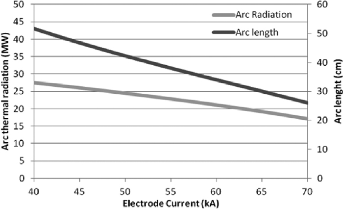
The theoretical model for arc radiation, introduced by Dittmer& Krüger,4) is found to be useful for estimating the incremental arc radiation by lengthening the arcs. The increase in arc lengths can be obtained by increasing the arc voltage. Figure 8 shows the estimation on radiation power for the studied AC-EAF. In this figure, the electrode current is in the range from 40 to 70 kA and it can be noticed how the arc length is decreased from 51 to 26 cm by increasing the electrode current, and, at the same time the amount of the arc power converted to thermal radiation is also decreased from 27 down to 20 MW.
When the arc is unstable, in main melting, the thermal radiation model can be used to estimate the amount of power dissipated by radiation. Since lowering the arc current may imply a reduction in the power input, (for currents at the left of the peak arc power in the EAF power curve), then a criteria to define operational current is when the decrement in power input is not longer compensated by the increase in the proportion of arc radiation due to the increase in the arc length. This would be the “energy efficient” current setpoint for a given tap during melting in presence of scrap.
4.4. Energy Efficient Power Levels
If arc conditions and heat stages are properly determined, the optimal (energy efficiency wise) power levels to the EAF can be selected under the following criteria for the main scenarios in a heat process:
1) First, when the arc is unstable in presence of scrap, increase thermal radiation of the electric arc. This is, if the arc is unstable and uncovered, increasing the arc thermal radiation is useful to melt the scrap even allowing a slightly increase in arc instability.
2) Second, when the arc is stable, the furnace can be operated at a maximal useful arc power with the current setpoints proposed by this research work. This is to transfer the useful arc peak power to the slag covered electric arcs.
3) Third, when the arc is stable but not covered by slag, then the furnace can be operated at peak arc power. This is to operate at higher current setpoint to shorten the arcs.
It can be noticed that all three proposed operational current setpoints are defined with an energy efficiency criteria since they operate lower current setpoints which implies lower power circuit losses and lower “fall region losses”.
5. Experimental Results
5.1. Current Setpoints for Experimental Power Profile
Experimental work was done at Tenaris-Tamsa steelmaking plant in Veracruz, Mexico. Several power profiles were designed and experimentally tested at a 120 MVA AC EAF. This furnace has a capacity of 150 tons (tapped steel) and is typically charged with 170 tons of metallic charge in two buckets. The current setpoint corresponding to a power level for each one of the heat stages were automatically applied to the arc regulation system. In the experimental power profile the tap 9 (943 V) was used for melting and tap 8 (913 V) for initial bore-in and final refining/heating. The electrode current used during early and main melting was reduced from 56 kA in the original (regular practice in Tenaris-Tamsa) power profile down to 53 kA in the experimental profile, proposed with our methodology. The current values were estimated using Eq. (16) and the EAF parameters shown in Table 1. Minimum values were set to 53 kA for early melting and 58 kA for late melting and then incorporated into the power profile of Table 2. The MIN current setpoint corresponds to the current setpoint obtained with the greater arc reactance and the MAX setpoint is obtained with the lower arc reactance and they are applied accordingly to the arc conditions (unstable or stable), detected by the signal processing of the virtual neutral to ground voltage previously reported in.21)
Table 2.Current setpoint for original and experimental profiles.
| Heat Stage | TAP (Voltage) | Original Power Profile Current Setpoints (kA) | Experimental Power Profile Current Setpoints (kA) |
|---|
| MIN | MAX | MIN | MAX |
|---|
| Bore Down | 8 (913 V) | 58 | 58 | 55 | 55 |
| Early Melting | 9 (943 V) | 56 | 59 | 53 | 56 |
| Main Melting | 9 (943 V) | 56 | 60 | 53 | 58 |
| Late Melting | 9 (943 V) | 59 | 61 | 58 | 60 |
| Refining/Heating | 8 (913 V) | 61 | 62 | 58 | 60 |
During the experimental heats other systems for chemical energy input were operated without changes in their control profiles, this is, oxy-gas burners, carbon and oxygen lances operated at the same values dictated by operational practices in use, same tapping temperatures and comparable primary voltage level. Figure 9 shows power measurements (active and reactive) versus electrode currents to compare power curves of the original (normal practice) power program with the experimental (proposed in this work) power program proposed for energy optimization. In both figures, the four rectangles superimposed to the curves indicate the ranges of operational current and their obtained powers, the rectangles at the left for main melting (unstable arcs), and the rectangles at the right for late melting and refining/heating (stable arcs).

The active and reactive power measurements of a heat show tremendous dispersion because of the dynamical characteristics of the electric arcs during the melting and heating process. Figure 9 shows the power versus current measurements for two selected heats for comparison, the upper charts shows the power measurements using the original power profile (common practice), and the lower chart shows measurements obtained with the experimental power profile (our proposal to save energy). It can be noticed how the furnace power was decreased moving the current ranges from around 52 to 58 kA for unstable melting (Fig. 9, upper chart) down to around 48 to 56 kA (Fig. 9, lower chart) and from around 58 to 64 kA (Fig. 9, upper chart) down to 57 to 63 kA (Fig. 9, lower chart) for late meltdown and refining (stable arc conditions). The new experimental power profile proposed in this work, based on the estimation of the optimum current to get the peak arc power, was tested for 3 heats and the results obtained are shown in Table 3, which indicates the total active (kWh), reactive (kVArh) and specific energy consumptions per ton of tapped steel (kWh/t), as well as the power factor, and the power on time.
Table 3.Results of experimental heats.
| Heat Number | kWh | kVArh | Power Factor | Power-On Time (min) | kWh/t | Average Power (MW) |
|---|
| 55420 | 56304 | 33120 | 0.8619 | 49 | 392.69 | 68.9 |
| 55421 | 55944 | 32940 | 0.8617 | 48 | 387.09 | 69.9 |
| 55422 | 56376 | 33120 | 0.8622 | 49 | 393.32 | 69.0 |
| Experimental Heats (Averages) | 55421 | 33060 | 0.8619 | 48.67 | 391.03 | 69.27 |
| Original Heats (Averages) | 63580 | 38590 | 0.85 | 54 | 423.75 | 69.8 |
Results of Table 3 show a decrement in energy consumption from 63.58 down to 55.42 MWh per heat, equivalent to a reduction from 423.75 down to 391.03 in specific energy consumption (kWh/t). This energy savings can be explained because the operation at lower current setpoints implies several benefits: First, increase in electrical efficiency due to the reduction of line losses; second, a higher arc voltage is obtained as a consequence of the reduction in the voltage drop across the furnace impedances due to the decrease in average current; and third, higher arc thermal radiation is achieved in the three phases due to the operation at longer arcs, this implies an increase in the thermal efficiency while the arcs are shielded by scrap or covered by slag. In this way the EAF can work in points with higher electric energy efficiency. This increment in the energy efficiency in the EAF was obtained only by modifying current setpoints in the power profiles, i.e. without changing the tap of the step down or furnace transformer and using the same operational practices for other chemical energy inputs and aiming the same tapping temperatures.
6. Conclusion
A theoretical and practical analysis of the arc power considering the operational reactance is proposed in this work. Formulas of arc length and arc thermal radiation are also useful to estimate the arc radiation under unstable arc conditions and this justifies the use of longer arcs to increase the proportion of arc radiation to total active power to melt scrap more efficiently. The power related to the cathode and anode voltage drops at the electrodes fall regions, is proposed to be considered as energy losses. These losses are relevant in the definition of the operational current point during stable arc conditions. Power curves can be obtained with simple calculations and by using this methodology it is possible to determine operational ranges with lower electrode current where the arc power has its peak value.
Estimating both the power circuit losses and the fall region losses combined with the estimated increase of radiation by lengthening the arcs helps to better define lower operational currents setpoints that resulted to be as well more “energy efficiency” operational ranges in arc power during the different heat conditions. The above experimental results confirm the advantage of operating higher voltages during the melting period and slightly higher voltage during the flat bath arc conditions. The increase in the arc voltages, due to lower voltage drops in both, the transformer and feeder impedances is a key factor to explain the increase in arc thermal radiation, thus the thermal efficiency.
The ideas here in proposed are applied for the design of a new and better power profile at a real EAF facility. The optimization of the power control make possible to reduce the total energy needed to produce molten steel. Electrical efficiency is increased due to the reduction in losses at both the furnace resistance and the transformer internal resistance. It can be said, that to increase the energy efficiency of the electric arc furnaces the main opportunity is in the use of longer arcs in presence of scrap to increase the arc thermal radiation; another fact is that the average power needs to be reduced in order to reduce the energy consumption and improve efficiency. The obtained results can be explained only because the power control of the EAF was operated at higher efficiency. In this way it was experimentally probed that is possible to find a more economical operation of the EAF power control without affecting productivity.
Acknowledgements
This research was done in Cathedra Roberto Rocca sponsored by Tecnológico de Monterrey, TERNIUM, TENARIS-TAMSA and CONACYT and is a collaborative work among the Tecnológico de Monterrey and the Universidad Nacional Autónoma de México.
References
- 1) A. Muhlbauer, A. Von Starck and C. Kramer, Ed.: Handbook of Thermoprocessing Technologies, Vulkan Verlag, Germany, (2007), 209.
- 2) B. Bowman and K. Krüger: Arc Furnace Physics, Verlag Stahleisen, Düsseldorf, Germany, (2009), 121.
- 3) Y. Toulouevski and I. Ziburov: Innovation in Electric Arc Furnaces, Springer, Heidelberg, (2009), 10.
- 4) B. Dittmer and K. Krüger: Elektrowärme Int., 4 (2009), 195.
- 5) S. Köhle, M. Knoop and R. Lichterbeck: Elektrowärme Int., 51 (1993), 175.
- 6) T. E. Miller: Reactive Power Control in Electric Systems, Wiley-Interscience, Hoboken, (1982), 304.
- 7) J. L. G. Sanchez, M. A. Ramirez-Argaez and A. N. Conejo: Steel Res. Int., 80 (2009), 123.
- 8) D. Guo and G. Irons: CSIRO 3rd Int. Conf. on CFD, Melbourne, Australia, (2003), 223.
- 9) A. Z. Nemirovskii and F. Puchkarev: J. Phys. D: Appl. Phys., 25 (1992), 798.
- 10) J. W. McKelliget and J. Szekely: J. Phys. D: Appl. Phys., 16 (1983), 1007.
- 11) M. Ushio, J. Szekely and C. W. Chang: Ironmaking Steelmaking, 6 (1981), 279.
- 12) V. Logar, D. Dovžan and I. Škrjanc: ISIJ Int., 51 (2011), 382.
- 13) P. F. Ryff and V. Bulat: IEEE-IAS Annual Meeting Conf. Record, Piscataway, NJ, (1981), 952.
- 14) K. Timm: 5th Int. Symp. Electrical Engineering of Arc Furnaces, Kehl, Germany, (2005), 1.
- 15) J. Bakken, L. Gu, H. Larsen and V. Sevastyanenko: J. Eng. Phys. Thermophys., 70 (1997), 1.
- 16) T. Poppe, D. Obradovic and M. Schlang: Siemens Rev., 4 (1995), 24.
- 17) W. Staib: Steel Technology Int., Sterling, London, (1993), 103.
- 18) R. Sesselmann, F. J. Wahlers, H. Zöcher and T. Poppe: 5th European Electric Steel Cong., Paris, France, (1995), 260.
- 19) R. Gerling, T. Louis, G. Schmeiduch, R. Sesselmann and A. Sieber: Metall. J., 53 (1999), 410.
- 20) M. Bianchi and R. Langella: AISE 2000, Pittsburgh, PA, USA, (2000), 1.
- 21) F. Martell, A. Deschamps, R. Mendoza, M. Meléndez, A. Llamas and O. Micheloud: ISIJ Int., 51 (2011), No. 11, 1846.