Regular Article
Innovative Method on Simulating the Damage Mechanism of the Refractory
2013 Volume 53 Issue 7 Pages 1275-1279
Details
2013 Volume 53 Issue 7 Pages 1275-1279
The presentation of the simulating method of the refractory damage is the subject of this paper. Based on the assumption of uniform temperature, the two kinds of load of compression and tension are endowed with two different kinds of damage models. In the tension state, the matrix is gradually amalgamated with stomata, at the same time, the aggregate is “swallowed” by the amalgamated matrix; On the other hand, in the compression state, only the matrix is amalgamated with stomata and the aggregate remains unchanged. According to the hypothesis proposed, the damage is simulated by the improved Generalized Self-Consistent Scheme (GSCS). Contrast to the experimental data, the numerical results indicate that the introduction of the damage hypothesis is feasible.
Refractory materials are widely used in the iron and steel making process, especially in the building of superstructures and side walls of fusion furnaces. An adequate design of refractory material is a key to successful practice in this process. In this point of view, as a critical technique in the appropriate designing for the refractory, the simulation to predict the properties plays an important role in it. So far, magnesia-carbon products are especially used as ladle blocks for the fusion of highly corrosive steel melted at very high temperature, due to their high corrosion resistance and their low generation of steel defects generation. The presence of this high amount of magnesia-carbon in the refractory can be responsible for micro-damage occurrence during the repeated load step after melt casting (annealing), exhibiting highly nonlinear behavior.
In fact, the heterogeneity of industrial refractory materials results from their multiphase composition involving aggregates of different sizes, bonding phases and various additives. The grains arrangement, the shape of aggregates and the micro-structural defects such as porosity and cracks, make difficult the prediction of the mechanical behaviors.1)
While the mechanical behavior is mostly well known, their damage and time-to-failure mechanisms still require a better understanding. A number of studies on the evolution of the mechanical properties of the refractory materials related to different thermal treatments corresponding to their conditions of use are implemented in experimental ways, but for brittle solids the dominant mechanism is associated with crack damage and the governing property is influenced by the temperature as well as the load conditions such as loading mode and load velocity. Furthermore, the elastic properties (Young’s modulus) exhibit highly nonlinear damage not only for the reason that of the mismatch of coefficient of thermal expansion (CTE) happens in the interface, but also for the chemical phase transformations which is far beyond mono-damage.2,3,4,5,6,7) Set aside the temperature factor for the moment, it might be a more feasible way to study the micro-damaging mechanism from the point of view of micromechanics in advance. In the case of room temperature it is effective and convenient to design and conduct the test as you need in the interpretation of the determinant, for instance for the discrepancies of the Young’s modulus under different loading conditions.8) The difficulty is increased because these refractory materials present great contrasts of mechanical behavior and properties. Some answers are proposed to find the true properties to introduce in that analysis, but much effort was put on the design of the test method rather than on the analysis of the damage mechanism. Besides, conventional data collection method lacks the further description for the micro-damage mechanism of the refractory, which only offers limited depiction without an accurate explanation of the evolution of the damage. Therefore, in succession on the basis of previous studies, it is in dire need of finding a more appropriate way to investigate the damage. One of the aims of this paper is to identify the micro-damage mechanisms occurring in refractory materials in order to express the nonlinear behavior in a numerical approach.
In this paper, avoiding the complex discrimination on the process of material damage, an innovative method is put forward to simulate the nonlinearity of the refractory damage. At first, in the tension state, the matrix is gradually amalgamated with stomata, at the same time, the aggregate is “swallowed” by the amalgamated matrix; On the other hand, in the compression state, only the matrix is amalgamated with stomata and the aggregate remains unchanged. In the next part, according to the hypothesis proposed, the damage is simulated by the improved GSCS. Contrast to the experimental data, the numerical results indicate that the introduction of the damage hypothesis is feasible.
The damage behaves as the residual strain and the reduction in stiffness, which can be explained from the microstructure of the material and considered that the micro-cracks arise in the carbon and around the aggregate. Meanwhile, the sliding and crushing of graphite flake in carbon can also cause the non-linear behavior of material.9) Based on observation, the mechanism between tension and compression is different. When the material is loaded under tension, two types of damage occur simultaneously: the micro-cracks forming in the matrix, at the same time, because of the weak strength between the matrix and the aggregate, the deboned zone will appear in the interface, which will cause the reduction of the strength of the aggregate. Once the damage process is completed, the aggregate will not make any contribution to the overall stiffness of material and can be viewed as stomata.
Based on the assumption proposed upwards, the damage model is put forward: the reduction of the strength of the aggregate is regarded as the decrease in volume of aggregate; on the other hand, the reduction of the strength of the matrix developed by the micro-cracks is regarded as the combination of matrix and stomata which is formed by the volume empty out by the aggregate (Fig. 1). Without considering the rupture of material, as soon as the material achieves the strength limit, the interface is considered to be separated totally and the damage process is regarded to be finished, and the aggregate will not make any contribution to the stiffness of the material. Through this method can we simplify the complex damage process and express the non-linear behavior quantitatively.

The model in tension.
When the material is loaded under compression, it is assumed that only one type of damage occurs in the material: the micro-cracks forming in the matrix. Whereas the interface is not affected in the process because the strength of aggregate is much higher than matrix under compression (Fig. 2).

The model in compression.
As the multi-phase composite, the aggregates of the refractory are dispersed, which can be predicted by employing the micro-mechanical model: GSCS.10)
Consider an N-phase composite in which the matrix is denoted by the index r = 1, and the inclusion phases by r = 2, 3, … , N. The present work deals in particular with composites in which the inclusion phase consists either of spherical particles or aligned cylindrical fibers with a circular cross section. The fundamental equations needed for the determination of the effective stiffness of the composite can be obtained by applying homogeneous boundary conditions of the type:
| (1) |

Generalized self-consistent model.
Effective elastic properties can be expressed as:
| (2a) |
| (2b) |
Because there are only two independent constants of the four (volume modulus K, shear modulus G, elastic modulus E and Poisson’s ratio v), in accordance with(3a),(3b),(3c), from any two elastic constants of K, G, E, v, we can identify two other elastic constants. From the volume modulus K and shear modulus G obtained, using the relationship of the elastic modulus E, Poisson’s ratio v and the Lame coefficient λ (formula3), we can calculate the elastic properties of material:
| (3a) |
| (3b) |
| (3c) |
It is convenient to calculate the property of the material as long as we know two of the three known properties of the material.
2.4. Technology RoadmapThe volume content of the matrix phase is Cm, the volume content of the aggregate is Ci. Divide the damage process into N steps, and the transferring volume content in the nth iteration is Ci/N.
The first homogenization: In the iteration of the nth step, the matrix phase and the interfacial phase will be in homogenization, and the volume of interface is (Ci /N)/(Cm + n Ci/N);
The second homogenization: In the iteration of nth step, the new matrix phase and the remaining aggregate will be in homogenization, and the volume of interface is (Ci – n Ci/N).
Figure 4 shows the calculation process:

Technology roadmap.
E(σ) can be obtained from the upper simulation. As we know that E(σ)=dσ/dε, we can get the expression by integral relationship:
| (4) |
| (5) |
The industrial refractory materials studied were composed of magnesia aggregates and a binder (phenolic resin or pitch) containing in some cases graphite and/or additional metallic elements (aluminum, silicon). Figure 5 shows an example of such microstructure. The magnesia aggregates were formed by sintering of crystallites with weak interfaces. The magnesia grain size varied from less than one half millimeter up to five millimeters. The other compound (SiO2, Al2O3) impurities were very thin and scattered in the carbon binder.

Typical microstructure of magnesia carbon refractory.
The components were mixed and shaped into bricks at low temperature (20–50°C) and under high pressure (150 MPa around). Then the bricks underwent heat treatment (100–200°C) to start the polymerization of resin and to eliminate residual water and phenols. Table 1 provides the composition of the materials after the heat treatment.
| Chemical composition, % (weight) | Phase composition, % (volume) | ||||
|---|---|---|---|---|---|
| MgO | C | SiO2 | Al3O3 | Aggregate phase | Continuous phase |
| 82.95 | 13.07 | 0.72 | 0.61 | 65 | 35 |
The refractory material can be regarded as two-phase composite material: MgO is aggregate phase and C is matrix phase. At room temperature, the porosity of the refractory is low (2.4%) which can be ignored. Table 2 lists the elastic properties of MgO and the matrix phase C which can be obtained from the literature.9)
| composition | Elastic modulus E (GPa) | Poisson υ |
|---|---|---|
| MgO | 248 | 0.23 |
| C | 5 | 0.12 |
| stomata | – | – |
The equivalent bulk modulus and effective shear modulus could be obtained according to the local property and composition of particle phase and matrix phase. The predictive modulus of magnesia carbon refractory by employing GSCS is 22.98 GPa; Poisson’s ratio is 0.15 which are in accordance with the literature.9)
3.2. Improved GSCSFigure 6 shows the technology roadmap for the improved GSCS:

The technology roadmap of improved GSCS.
The first scale homogenization: The bond of refractory is composed of amorphous carbon, graphite, stomata and micro cracks. Amorphous carbon and graphite have similar properties, which both contain micro-cracks of high density. These cracks weaken the differences of the mechanical properties. Meanwhile, dispersion of graphite reduces the performance of its strong anisotropy. Therefore, the stomata phase mainly locates in the carbon phase. Based on the assumption can we calculate the property of multi-porous carbon matrix by GSCS;
The overall scale homogenization: Based on observation, all aggregate is surrounded by the porous carbon phase, and we can calculate the overall property by GSCS again under the premise of the first scale.
As the introduction, in the tension state, the reduction of the strength of the aggregate is regarded as the decrease in volume of aggregate; on the other hand, the reduction of the strength of the matrix developed by the micro-cracks is regarded as the combination of matrix and stomata which is formed by the volume empty out by the aggregate. In the compression state, it is assumed that only matrix damage occurs in the material. According to the Griffith theory of plastic mechanics, the fracture strength is E/7, thus only the first 4 steps are taken as the effective steps. The results are listed in Tables 3 and 4.
| Iterative steps | MgO% | C% | stomata% | The volume fraction of stomata after the first homogenization | The E of continuous phase after the first homogenization | The volume fraction of aggregate after the second homogenization | The overall E of continuous phase after the second homogenization | equivalent tensile modulus |
|---|---|---|---|---|---|---|---|---|
| 0 | 65 | 35 | 0 | 0 | 5 | 65 | 22.98 | 35.9 |
| 1 | 58.5 | 35 | 6.5 | 15.66 | 3.63934 | 58.5 | 13.99 | 21.859 |
| 2 | 52 | 35 | 13 | 13.54 | 2.76771 | 52 | 8.9324 | 13.957 |
| 3 | 45.5 | 35 | 19.5 | 11.93 | 2.17566 | 45.5 | 5.93665 | 9.276 |
| 4 | 39 | 35 | 26 | 10.66 | 1.75524 | 39 | 4.079 | 6.373 |
| 5 | 32.5 | 35 | 32.5 | 9.63 | 1.4461 | 32.5 | 2.881 | 4.502 |
| 6 | 26 | 35 | 39 | 8.78 | 1.21216 | 26 | 2.08387 | 3.256 |
| 7 | 19.5 | 35 | 45.5 | 8.07 | 1.03079 | 19.5 | 1.53763 | 2.4025 |
| 8 | 13 | 35 | 52 | 7.47 | 0.8873 | 13 | 1.15422 | 1.8035 |
| 9 | 6.5 | 35 | 58.5 | 6.95 | 0.77182 | 6.5 | 0.879 | 1.3734 |
| 10 | 0 | 35 | 65 | 6.5 | 0.677497 | 0 | 0.677497 | 1.05859 |
| Iterative steps | MgO% | C% | stomata% | The volume fraction of stomata after the first homogenization | The E of continuous phase after the first homogenization | The volume fraction of aggregate after the second homogenization | The overall E of continuous phase after the second homogenization |
|---|---|---|---|---|---|---|---|
| 0 | 65 | 35.0 | 0.0 | 0 | 5.00 | 65 | 22.98 |
| 1 | 65 | 31.5 | 3.5 | 10 | 4.66 | 65 | 21.00 |
| 2 | 65 | 28.0 | 7.0 | 20 | 3.81 | 65 | 17.93 |
| 3 | 65 | 24.5 | 10.5 | 30 | 3.12 | 65 | 14.86 |
| 4 | 65 | 21.0 | 14.0 | 40 | 2.55 | 65 | 12.29 |
| 5 | 65 | 17.5 | 17.5 | 50 | 2.08 | 65 | 10.12 |
| 6 | 65 | 14.0 | 21.0 | 60 | 1.70 | 65 | 8.34 |
| 7 | 65 | 10.5 | 24.5 | 70 | 1.39 | 65 | 6.87 |
| 8 | 65 | 7.0 | 28.0 | 80 | 1.13 | 65 | 5.61 |
| 9 | 65 | 3.5 | 31.5 | 90 | 0.92 | 65 | 4.59 |
| 10 | 65 | 0.0 | 35.0 | 100 | 0.75 | 65 | 3.76 |
Seen from the result, one can notice that it’s feasible to simulate the nonlinear mechanical behavior of refractory by employing this method, in that the numerical results can be in good accordance with the experiment. Figure 7 shows the curve of E-Stress with different fraction of aggregate under tension. From the comparison one can find that the aggregate in higher volume fraction can improve the initial elastic modulus of material, whereas it can also accelerate the damage of material and behave brittleness. Figure 8 shows the curve of E vs. stress under compression. The stress-strain curve is given in Fig. 9 where the strain corresponds to that in the experiment. The loading path is well reproduced except for that the prediction is smaller than the experiment in the initial load state because of the brittleness of the material for which a more sophisticated model would be needed for the determination of the initial conditions. Yet in the final state of load the results match each other again, which means it’s reasonable to simulate the nonlinear tendency through this method.

The curve of E vs. stress with different fraction of aggregate under tension.
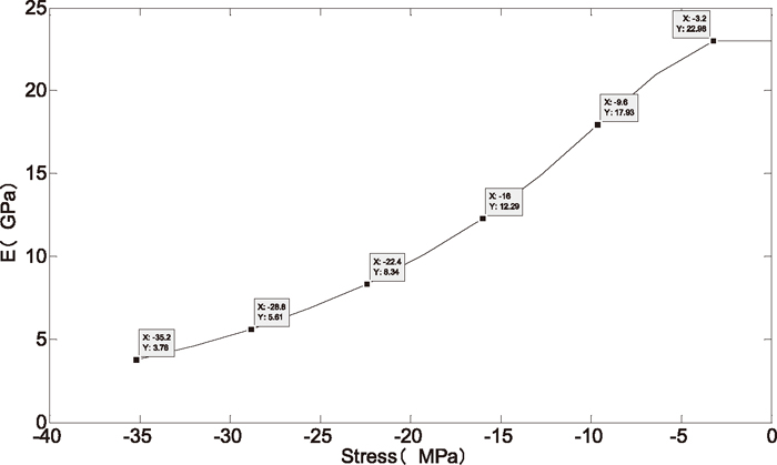
The curve of E vs. stress under compression.

Stress vs. strain curves: prediction and experiment.
Refractory exhibits great discrepancies under different load conditions, such as tension and compression test. In the past, Schacht found out from a large number of tests that: the E derived from the compression test is 36% lower than that derived from the tension test.9) At the same time, generalized self-consistent model could only be used to predict the compressive elastic modulus under the state of no damage. However, GSCS is adaptable in the assumption because: after homogenization the interface could still be regarded as undamaged and iterated with GSCS.
According to the theory of micromechanical and GSCS, two kinds of load of compression and tension are endowed with two different kinds of damage models. In the tension state, the matrix is gradually amalgamated with stomata, at the same time, the aggregate is “swallowed” by the amalgamated matrix; On the other hand, in the compression state, only the matrix is amalgamated with stomata and the aggregate remains unchanged. Based on the hypothesis proposed, the damage is simulated by the improved GSCS. Avoiding the complex discrimination on the process of material damage, the numerical results indicate that the introduction of the damage hypothesis is feasible.
The authors would like to thank the National Natural Science Foundation of China (51075310), the Research Fund for the Doctoral Program of Higher Education of China (20114219110003), the Hubei Province Natural Science Fund Project (2012FFA022) and Program for New Century Excellent Talents in University of Ministry of Education of China (NCET-12-0715) for the financial support.