Review
Mechanical Anisotropy in Steels for Pipelines
2013 Volume 53 Issue 8 Pages 1305-1314
Details
2013 Volume 53 Issue 8 Pages 1305-1314
There has been a huge expansion in the laying of pipelines for the transmission of fossil fuels over large distances and in dire environments. Large diameter pipes can be manufactured by welding spirals of hot–rolled linepipe steels. This process has a cost advantage relative to one in which the steel is seam welded after bending into a tubular shape. However, one particular problem associated with the steels used to fabricate the pipes is that of the anisotropy of mechanical properties, especially the toughness. Even though properties such as the Charpy toughness and strength meet minimum specifications, the existence of orientation dependence can compromise, for example, the stability of the pipe to buckling. There is, therefore, a large international activity on understanding the anisotropy of pipeline steels. This review represents an attempt to critically assess the steels and the orientation dependence of their mechanical properties, with the aim of establishing a basis for further progress.
Steels are the material of choice when fabricating pipes for the economic transmission of crude oil and natural gas from remote regions to populated areas where the fuels are exploited in the generation of energy. Table 11) illustrates the intensity of current activity in pipe laying that is currently in progress. There are many kinds of steels used in the fabrication of pipes, some of the strongest of which are not fully established. The American Petroleum Institute (API) specifications of the popular alloys which have seen large scale applications are listed in Table 2.2) The grade designation follows the standards of the API and is categorised by the minimum yield strength requirement in ksi, for example X42, X60, X80 and so on.
| Region | Length / km | Steel |
|---|---|---|
| North America | 11000 | X80/X100 |
| Russia | 2000 | X80 |
| China | 8000 | X80 |
| Europe | 500 | X80 |
| Grade | C | Mn | Si | P (ppm) | S (ppm) | Nb+Ti+V | Cr | Cu | Ni | Mo | B (ppm) | YS (MPa) | TS (MPa) | YR (%) |
|---|---|---|---|---|---|---|---|---|---|---|---|---|---|---|
| X65 | ≤ 0.12 | ≤ 1.60 | ≤ 0.45 | ≤ 250 | ≤ 150 | ≤ 0.15 | ≤ 0.5 | ≤ 0.5 | ≤ 0.5 | ≤ 0.5 | – | 450–600 | 535–760 | ≤ 93 |
| X70 | ≤ 0.12 | ≤ 1.70 | ≤ 0.45 | ≤ 250 | ≤ 150 | ≤ 0.15 | ≤ 0.5 | ≤ 0.5 | ≤ 0.5 | ≤ 0.5 | – | 485–635 | 570–760 | ≤ 93 |
| X80 | ≤ 0.12 | ≤ 1.85 | ≤ 0.45 | ≤ 250 | ≤ 150 | ≤ 0.15 | ≤ 0.5 | ≤ 0.5 | ≤ 1.0 | ≤ 0.5 | – | 555–705 | 625–825 | ≤ 93 |
| X100 | ≤ 0.10 | ≤ 2.10 | ≤ 0.55 | ≤ 200 | ≤ 100 | ≤ 0.15 | ≤ 0.5 | ≤ 0.5 | ≤ 1.0 | ≤ 0.5 | ≤ 40 | 690–840 | 760–990 | ≤ 97 |
| X120 | ≤ 0.10 | ≤ 2.10 | ≤ 0.55 | ≤ 200 | ≤ 100 | ≤ 0.15 | ≤ 0.5 | ≤ 0.5 | ≤ 1.0 | ≤ 0.5 | ≤ 40 | 830–1050 | 915–1145 | ≤ 99 |
The actual chemical composition can vary within these specification ranges and the details are sometimes proprietary; for example, it is rare for X65 to contain a carbon concentration which is as high as 0.12 wt%. Typical compositions of X65, X70 and X80 steels from published literatures are listed in Tables 3, 4 and 5 respectively. Normally, the steels are sufficiently clean to avoid unnecessary inclusions with very low sulphur level for good resistance to the hydrogen–induced cracking.3,4,5) Also these have excellent weldablilty with low carbon level.6)
;%0A%09%09%09newWindow.document.open();%0A%09%09%09newWindow.document.write('<img src=%22./Graphics/53_1305_tbl_1.jpg%22>');%0A%09%09%09newWindow.document.close();%0A%09%09) |
;%0A%09%09%09newWindow.document.open();%0A%09%09%09newWindow.document.write('<img src=%22./Graphics/53_1305_tbl_2.jpg%22>');%0A%09%09%09newWindow.document.close();%0A%09%09) |
;%0A%09%09%09newWindow.document.open();%0A%09%09%09newWindow.document.write('<img src=%22./Graphics/53_1305_tbl_3.jpg%22>');%0A%09%09%09newWindow.document.close();%0A%09%09) |
There are many technical challenges for linepipe steels, including a need for homogeneous microstructure and properties, weldability, a low yield to ultimate tensile strength ratio consistent with safe design, and obviously, an adequate level of toughness. Indeed, the quality required is now much more demanding given the often difficult environments where the pipes must be installed, for example in exceptionally deep oceans off the coast of Brazil, on undulating land surfaces, and in freezing climates. It is fortunate therefore, that the steel industry has, with careful microalloying and thermo–mechanical controlled processing (TMCP),7,8,9,10) brought the X80 grade to a technological readiness level where the X80 grade is now in its final form and in service – in the aerospace industry, this corresponds to ‘flight–proven’. The higher strength associated with X80 when compared with X65 permits fluids to be transmitted at higher pressures, or depending on design criteria leads to a reduction in self–weight in the case of hanging structures. The toughness is vital, amongst other factors in ensuring the arrest of high–velocity cracks.11,12,13,14) Low–grade petroleum wells contain hydrogen sulphide gas which makes the steels susceptible to hydrogen–induced and stress–corrosion cracking. Further issues arise when changes occur, for example in the yield strength, after pipe–forming, with a resultant increase in the ductile–brittle transition due to the work of hardening15,16)
These and other requirements needed to ensure integrity during service are well–known and to a large extent understood and incorporated into practice, both via specifications and detailed analysis. The physical metallurgy aspects have been reviewed, each with different emphasis.12,17,18,19,20,21,22,23) Our purpose here it to focus on the development of anisotropy in pipeline steels, particularly with respect to the toughness of the steel as measured using Charpy impact tests. Such tests record the energy absorbed on impact by a standard specimen as a function of the test temperature. The function is usually in the form of a sigmoidal curve with an upper shelf corresponding to the maximum absorption of energy by ductile fracture, a lower shelf representing cleavage (brittle) failure, and a transition temperature involving mixtures of the ductile and brittle modes. Anisotropy can arise in both the ductile and brittle modes of fracture.
As illustrated in Fig. 1, the orientation dependence of toughness is a well–known phenomenon for hot–rolled steels in general.24,25) As will be seen later, there is also considerable work in the context of pipeline steels. There are three particular factors which are emphasized in discussing toughness or the less pernicious strength anisotropy: non–uniform distribution in the size and shape of inclusions, microstructural anisotropy due to chemical segregation with banding or elongated grain structure, and crystallographic texture. In general, the role of inclusions and segregation is most prominent in the X65 or X70 grades steel, whereas the stronger variants are cleaner and transform at larger undercoolings so that they tend to have more homogeneous microstructures in spite of the segregation. Therefore, crystallographic texture may in such materials play the greatest role in determining the anisotropy of properties.
Inclusions influence anisotropy because they often are associated with the initial solidification process and any solidification–induced chemical segregation; others may precipitate in the austenite at high temperatures prior to the hot deformation that the cast steel is subjected to. Common inclusions include the manganese sulphides, silicates and alumina and combinations of oxides depending on the particular steelmaking route, and the hot deformation needed to shape the steel has the effect of orienting these phases along the principal plastic–strain directions. Some phases such as manganese sulphides and silicate can deform along with the steel and hence become elongated, whereas others fragment and form stringers along these same directions.26,27) The inclusions can as a consequence, lead to a variety of anisotropies, particularly with respect to tensile elongation, bend properties, fracture mode and fracture toughness. The fracture toughness where the Charpy specimen notch is in the rolling direction of the steel, is found to be much lower than when it is normal to that orientation.28,29,30,31,32) It is the directionality of MnS inclusions that is found responsible for the orientation dependence of toughness on the forging reduction ratio.33) A typical microstructure of ferritic grains, pearlite bands and shape of flattened MnS is illustrated in Fig. 2.34) Figure 3 illustrates impact energy values for two steels with different sulphur contents. The interesting observation is that the degree of anisotropy is less for the higher sulphur steel. This is because the sulphides in the low–sulphur alloy were relatively more elongated.35) These observations also emphasise the role of inclusions in nucleating and linking voids, since the data illustrated all represent the ductile mode of failure, so that the observed anisotropy is a direct consequence of the shape of the inclusions. It is important to note also that the sulphides may not be uniformly distributed within the steel in which case correlations of properties with the average concentration become less certain.36)
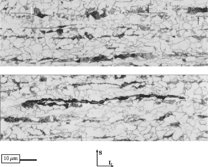
Steel microstructure consisting of ferritic grains, pearlite bands and shape of flattened MnS (arrows) and mixed oxide–MnS (white arrows) both in ferrite in upper image and crushed MnS in pearlite in lower image. ‘S’ and ‘L’ stand for the short transverse and longitudinal directions respectively. Reproduced from Ref. 34) with permission from Elsevier.
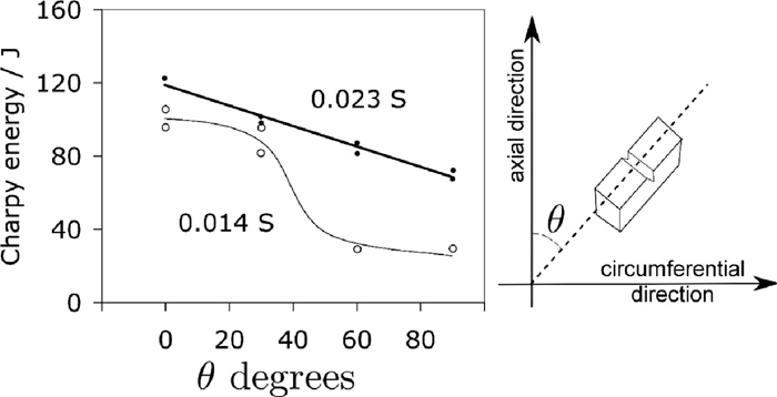
Charpy energy as a function of orientation and sulphur content (wt%). The tests were arranged so that all of the samples undergo ductile failure. Data for A106 grade B steel pipe, from Ref. 35).
Nonmetallic inclusions influence properties by nucleating cleavage or voids. It is often the case that the inclusions serve to concentrate stress so that adjacent, and more brittle cementite particles can initiate cleavage.37) This is because inclusions like MnS can lose cohesion with the matrix before the onset of cleavage. The resulting hole provides the greatest stress concentration at the tip of an elongated inclusion, so that loading normal to the plane of the inclusion leads to poor toughness, in contrast to the case where the principal loading is parallel to the long axis when the stress concentration due to decohesion is of minor importance. This of course, leads to anisotropy of toughness.37) The anisotropy can be reduced by using lower rolling reductions38) so that the inclusions themselves have smaller aspect ratios (length divided by thickness).
Inclusions are not simply a problem of pipelines or anisotropy, and many methods have been introduced over time to control the shape and size of nonmetallic particles, particularly the manganese sulphides. The most obvious is to reduce the concentration of sulphides but anisotropic toughness persists even when the concentration is much less than 0.01 wt%,28,39) presumably, as emphasised in,35) it is the shape of the particles that plays the major role in the orientation dependence of properties. Cross–rolling can mitigate the effects of manganese sulphide even when the sulphur concentration is as large as 0.06 wt%,28) but the method is not practical for most pipelines where the steel plate has to be long in one direction. The addition of cerium, zirconium or titanium helps reduce the plasticity of MnS, thus modifying the inclusion shape into a more spheroidal form.39)
Imai and co–workers did some interesting experiments in which the steel was heat–treated in a variety of ways to modify the deformed manganese sulphide present in the hot–rolled state (Fig. 4).40,41) Although the anisotropy in mechanical properties decreased when the layers were broken up into spherical particles, it was not completely eliminated when the sulphur concentration exceeded about 0.01 wt%. This is because at high concentrations, the spheroidised particles remained aligned as strings (Fig. 4(e)). Similar observations have been reported in the context of bearing steels subjected to rolling–contact fatigue, where strings of non–metallic particles aligned normal to the contact surface are much more harmful than those parallel to that surface,42) and there is a strong dependence of life on the length of these strings of inclusions.43)
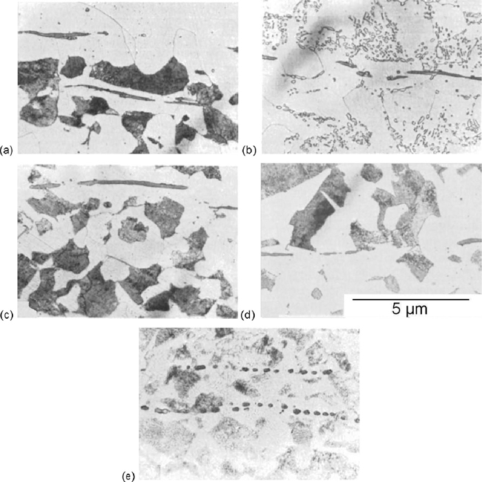
Fe–0.36C–0.22Si–0.73Mn–0.02P–0.025S wt%. (a) As–received hot–rolled condition. (b) Following spheroidisation heat–treatment involving dwell and cycling between 750 and 690°C followed by furnace cooling. (c) Austenitisation at 950°C for 1 h followed by air cooling. (d) Homogenisation at 1300°C for 1 h followed by furnace cooling. (e) Homogenisation at 1300°C for 4 h followed by furnace cooling. Reproduced from Ref. 40) with permission from Elsevier.
The role of inclusions in promoting the orientation dependence of toughness also is a function of the steel microstructure; a large fraction of pearlite reduces anisotropy by becoming the primary source for void initiation.40)
A typical microstructure in a hot–rolled low–alloy steel is known as the mixture of ferrite–pearlite and illustrated in Fig. 5(a).44,45) There are planner patches of pearlite parallel to the rolling plane. Microstructural banding is often more pronounced in sections containing the rolling direction than in those containing the transverse direction.46,47) Such banding is known to be responsible for the orientation dependence of properties,39,48) and homogenisation to mitigate the banding reduces anisotropy,49) but mostly in the ductile fracture regime rather than in the temperature range corresponding to the ductile–to–brittle transition.
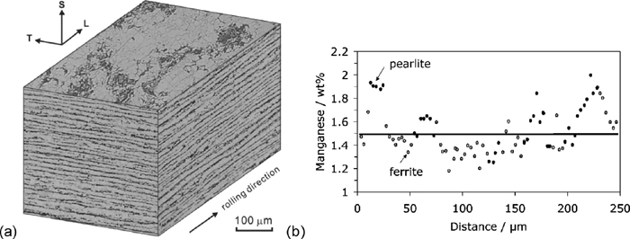
(a) Banding in hot–rolled ferrite–pearlite steel, Fe–0.15C–0.16Si–1.07Mn wt%. ‘S’, ‘T’ and ‘L’ stand for the short transverse, transverse and longitudinal directions respectively. Reproduced from Ref. 45) with permission from Elsevier. (b) The location of pearlite relative to the manganese concentration. Data from Ref. 46).
Banding occurs primarily because of the segregation of solutes in the last regions of the liquid to solidify during the cooling of steel from the molten state. The low–alloy steels which exhibit banding typically begin solidification as δ–ferrite so that elements such as manganese, silicon, phosphorus and sulphur are partitioned into the interdendritic regions which then solidify with a higher than average concentration of these solutes. Subsequent deformation, for example by hot–rolling, causes these regions to spread out as bands. The segregation of concern is of substitutional solute such as manganese (Fig. 5(b)). Carbon also segregates during solidification but it diffuses rapidly as the steel cools through the austenite phase field until its chemical potential becomes uniform. The silicon concentration, which is not illustrated in Fig. 5(b), was also found to be in phase with the pearlite bands. Although silicon is a ferrite stabiliser, its influence on the transformation in typical steels of interest here is much smaller than that of manganese.
The ferrite–pearlite banding evident in Fig. 5(a) occurs when the regions which are depleted in austenite–stabilising elements decompose into ferrite, before the transformation can occur in other areas.50) As a result, carbon is partitioned into the adjacent substitutional–solute rich austenite, which ultimately becomes the pearlite. The microstructural banding therefore correlates with the segregation pattern and the correlation becomes more pronounced when the microstructure is generated by slow cooling. This is because larger cooling rates are associated with greater undercoolings, which permit ferrite to form even in manganese–enriched regions.
A reduction in the carbon concentration also helps make the steel more isotropic because it is the partitioning of carbon into the manganese–rich regions that leads to the formation of pearlite bands.39)
The development of microstructural banding is illustrated in Fig. 6. As pointed out previously, the highly mobile carbon homogenises during cooling through the austenite phase field. However, there are gentle variations which occur in concert with the manganese, as the carbon maintains a uniform chemical potential in the austenite. Manganese lowers the activity of carbon and hence the manganese–rich regions are associated with a somewhat higher carbon concentration.51) The dependence of the spatial distribution of carbon on that of substitutional solute in austenite was originally thought to be the cause of banding.50) Bastien,52) however, considered the banding to be due to the substitutional solutes and Kirkaldy et al.51) later showed that this is indeed the dominant effect.
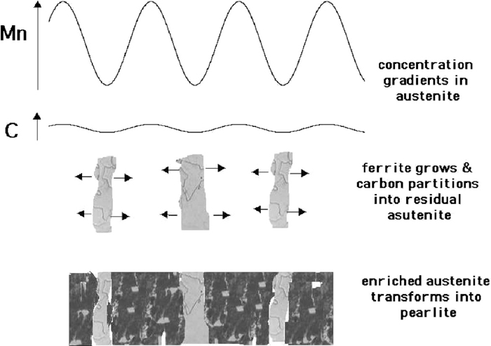
An illustration of the common mechanism of banding. Note that banding has irregularities so it is not entirely an accurate reflection of the chemical segregation pattern from Ref. 46).
An alternative mechanism is found in steels containing relatively large sulphur concentrations.53) Manganese sulphides precipitate in the regions containing a large average concentration of manganese. As a consequence, the manganese is bound in the sulphide which is surrounded by a manganese–depleted zone where ferrite forms. The ferrite partitions carbon into the adjacent zones which have a low average concentration of manganese, which transform into pearlite. The position of the ferrite bands is thus shifted into locations where the average Mn concentration is large, but where the Mn is tied up as sulphides (Fig. 7).
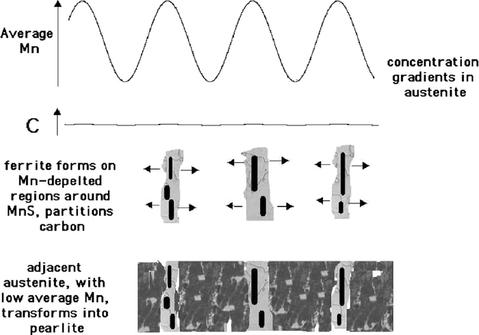
The mechanism of banding in steels containing substantial quantities of manganese sulphides.
Other kinds of microstructural anisotropy also has been shown to correlate with toughness in pipeline steels. Figure 8 shows the case for the X80 grade pipeline steel where the minimum in Charpy toughness in the ductile–brittle transition temperature range corresponds to the smallest fraction of lower bainite on the fracture plane. Also the study suggested that the non–uniform grain shape is related to the anisotropy of the Charpy toughness.54,55) One difficulty with this interpretation is that the fraction should be independent of the plane of section provided that the number of measurements made is statistically meaningful. It is also not clear why the minimum correlates with the smallest lineal intercept since a finer microstructural scale should lead to better toughness. As pointed out by Petrov et al., the real explanation in the context of the X80 steels is likely to be a complex combination of microstructure and crystallographic texture; the latter aspect is discussed in the next section.54,55) Kichkina et al. also discussed in ferrite–bainite microstructure that the bainite morphology oriented predominantly in the intermediate direction to the rolling direction, such as 50°, is needed to be considered for anisotropy of toughness in API–X70 steel, since the density of grain boundaries and interphase boundaries in that direction are minimum which is corresponding to the minimal obstacles of crack propagation.56) Sun and Boyd investigated the effect of processing parameter on anisotropy of cleavage fracture stress in microalloyed linepipe steel. The anisotropy of fracture stress increases with decreasing finish rolling temperature (FRT) above non–recrystallisation temperature of austenite and the factor for anisotropy was determined from microstructural anisotropy such as elongated grain and banding.57) Some early study also suggests that an elongated grain structure, for example that generated by warm–rolling with a low finish–rolling temperature, has been shown to cause variations in the tensile strength and impact properties according to direction relative to the elongated structure.58) Okuda et al. also reported that the ductile–to–brittle transition temperature (DBTT) in longitudinal direction is lower than transverse direction due to elongated grain in the extruded oxide dispersion strengthened (ODS) ferritic steels.59)
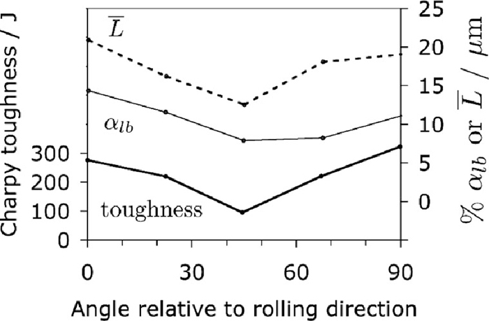
The Charpy toughness at –60°C, percentage of lower bainite (αlb) and mean lineal intercept as a function of the angle in degrees, relative to the rolling direction. Adapted from Ref. 54).
Work of fracture with microstructural banding has been related with orientation–dependence of impact properties. Joo et al. showed the case for the API–X80 grade linepipe steel with the minimum in Charpy toughness in the ductile–brittle transition temperature range corresponds to the absence of ‘split’ on the fracture plane. It established that Charpy specimens machined at 45° to the rolling direction with notches along the plate normals, performed relatively low impact toughness in the transition temperature regime and that was strongly affected by the occurrence or absence of split. It has been also confirmed experimentally by conducting Charpy tests with notches along the plate parallel and the source of split was discovered as the presence of microstructural banding, with variations in crystallography between adjacent bands.60) When in exaggerated form, the splitting during mechanical tensile or toughness testing is known sometimes as delamination. Such a split or delamination is illustrated in Fig. 9 and has been observed in the high–strength low–alloy steels,61,62,63,64) in ferritic stainless steels,65,66) ausformed alloys,67) marformed steels68) and low–carbon steels.69,70) Delamination is created by weakness parallel to the rolling plane within the steel, either because hot–rolling is terminated at temperatures within the α + γ phase field, texture, inclusion alignment on the rolling plane, intergranular failure along prior austenite boundaries, segregation of phosphorus and sulphur and any aspect that leads to anisotropic microstructure.71,72)
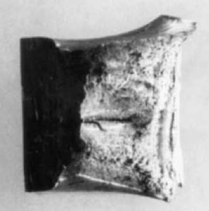
The feature normal to the length of the Charpy notch is a ‘split’ which influences the impact energy measured. Reproduced with permission of Elsevier from Ref. 74).
It has been suggested that the partial splitting of Charpy specimens during macroscopically ductile fracture, following an impact test, is related to separation on {100}α cleavage planes. Indeed, delamination is regarded macroscopically as brittle fracture behaviour which is concerned with a decrease of upper shelf energy in Charpy tests.73,74) It is suggested to lead to a decrease in toughness in the upper shelf regime, and in a reduction in the ductile–to–brittle transition temperature (DBTT). This does not seem correct; a decrease in DBTT is an increase in toughness, and the evidence has not been presented well to support this notion, and since the split is not parallel to the plane containing the notch, it could be argued that an improvement in toughness may follow due to the additional work of fracture at the split. However, if the separation occurs in the 100% ductile range then the impact energy decreases,74) but if it takes place at low temperatures then the enhancement of toughness is observed.75) So–called delamination toughening has long been known to lead to improved toughness in a wide variety of materials, for example in ceramic,76) carbon,77) and fine–grained steels.78,79,80,81) In particular, delaminations that form parallel to the plate surface can lead to a reduction in the impact transition temperature82) although excessive fissuring can compromise the upper shelf energy of Charpy tests.83) Indeed, it is not surprising that delamination is related to the toughness anisotropy.
Texture implies a non–random distribution of crystal orientations and clearly must influence the isotropy of a polycrystalline material. Kotrechko et al. investigated the effect of texture on the anisotropy of the cleavage stress of metals by theoretical calculation. It shows that the non–uniform distribution of crystallographic planes is the main reason for the cleavage–stress anisotropy in the textured polycrystals.84) Mintz et al. investigated the influence of texture on the impact properties of controlled rolled steels, and suggested that the role of texture on the directionality of impact properties is small and largely on ductile fracture.85) Inagaki and co–workers focused on controlled rolled high strength steel with several textured specimens of different chemical compositions. It showed that {100}α cleavage plane is related qualitatively to the anisotropy of toughness. In particular, it pointed out that anisotropy of toughness is induced with the {113} texture, which is placed between {110} and {112} planes, parallel to the rolling plane. Thus, the impact transition temperature peaked in the intermediate directions such as 45° to the rolling direction, and correlated this to the texture which favoured cleavage.86) Bourell and Sherby also discussed the effect of strong {001}<110> texture component corresponding to lower Charpy energy of diagonal specimens than that of longitudinal specimens at various test temperatures in warm–rolled low carbon steel.87) Joo et al. also pointed out that the {100}α cleavage plane is related to the orientation dependence of impact toughness especially in the DBTT regime60) and the effect of crystallographic texture itself is critically pronounced in that range of temperature.88)
The plates used in the manufacture of pipeline steels are thermomechanically processed and hence are textured. Baczynski et al. showed that components of the macroscopic texture can be correlated with the observed anisotropy of impact toughness in niobium–microalloyed steels. It is well known that in the ductile fracture region corresponding to relatively high test temperatures, the distribution of {110}α and {112}α slip planes has a greater influence on toughness than that of the {100}α cleavage–planes. The toughness anisotropy associated with ductile fracture correlates with the {112}<110>α component, and for cleavage fracture with the {001}<110>α and {110}<001>α components if they exist.84) Ju et al. also reported that the anisotropy of toughness at room temperature might be related to the distribution of {110}α planes as a function of angle relative to the circumferential direction in API–X65 linepipe steel.90)
Mechanical anisotropy depends on many factors other than texture, so it is not surprising that there are studies which reach the conclusion that crystallography has little or no role to play in determining the orientation dependence of properties. Mintz et al. found no indication of texture having any influence on the anisotropy of impact toughness in the transition temperature especially when the grain structure itself is directional, so the microstructural anisotropy is severe.58) Fegredo et al. found no significant relationship between toughness and the macroscopic texture in low–carbon steels containing 0.002–0.007 wt% sulphur, produced using different rolling temperatures.91) Microstructural anisotropy and elongated sulphides seemed to have the strongest influence. Kasada et al. investigated the effect of texture and microstructure on the mechanical anisotropy in hot–extruded bar of oxide dispersion strengthened (ODS) ferritic steels with {110} textured along the extrusion direction (ED) parallel to the rolling direction (RD), and the toughness anisotropy was induced by the combined effect of elongated grains and small particles along ED, not by texture.92) Petrov et al. reported that both microscopic and macroscopic textures had negligible influence on the anisotropy of properties in X80 steel, the main cause being associated with an uneven distribution of carbide–rich microstructural constituents.54,55) Pyshmintsev et al. also reported that the modern X80 linepipe tends to show no clear correlation between the {100}α planes and ductile fracture parallel to the rolling plane.93)
Mechanical anisotropy of the steel is essential because of unavoidable chemical segregation and/or thermo–mechanical working. Especially, the anisotropy of toughness is a particular problem, with toughness depending on the orientation relative to the rolling direction. In the context of linepipe steel, large–calibre spiral–welded pipes have not been exploited fully due to their anisotropy of mechanical properties and decrease in strength after pipe forming.15,16) The most critical issue is of course the circumferential direction of spiral–welded pipe, which normally experiences the highest load (hoop stress), would have weakest toughness and strength than other orientations.16) Consequently, this increases the chances of fracture.94,95)
An attempt has been established here to assess the potential causes for the orientation–dependence of toughness based on published work, in order to understand the phenomenon in linepipe steel. Three factors connected to the toughness anisotropy were highlighted: non–uniform distribution of inclusions with various sizes and shapes, microstructural anisotropy with banding and/or elongated grains with some work of fracture and non–random crystallographic texture. Therefore the toughness anisotropy is essentially complex due to the possible connections of the culprits. The relationship itself is not clear and significance of the factors is difficult to determine. However, hopefully this review is for the basis of the knowledge, can rouse the thoughts and indeed take one step further to understand the phenomenon. In doing so, we hope to set the scene forward for what is required both from an engineering and research point of view.
The authors are grateful for support from the POSCO Steel Innovation Programme, and to the World Class University Programme of the National Research Foundation of Korea, Ministry of Education, Science and Technology, project number R322008000101470.
