Abstract
Ni–Cr–Mo steels are widely used in machine part members, gears and shafts. Steels with higher carbon content (~1%) are used for heavy machine parts and bearings. Abrasive wear resistance is often a very important requirement for these high carbon steels, apart from sliding wear properties. In the present study, En31 steel was subjected to varying heat treatments to generate different microstructures. An attempt has been made to correlate the two body abrasive wear resistance with the bulk hardness and microstructures. The microstructures were studied through a combination of scanning electron microscopy (SEM), energy dispersive spectrometer attached to SEM (i.e. SEM-EDS) and X-ray diffraction (XRD). The bulk hardness decreased with increase in tempering temperature from 423 K to 848 K. The precipitation of Cr7C3 after 598 K tempering did not cause an appreciable increase in the hardness. At higher tempering temperatures (848 K), the martensite decomposed to give ferrite and cementite. The abrasive wear tests were carried out on hardened and tempered specimens. The abrasive wear mass loss increased with increase in the tempering temperature. Hardness had a direct correlation with the two body abrasive wear behaviour in En31 steel – increase in hardness increased the abrasive wear resistance. The important material removal mechanism were micro cutting and micro ploughing, the relative contribution of each to total wear loss was influenced by abrasive wear test conditions.
1. Introduction
Ni–Cr–Mo steels are widely used in applications like machine part member, bearings, shafts and gears. Steels with carbon content in the range 0.8–1.1 wt% and total substitutional solute content less than 3 wt% are particularly suitable for machine tools and bearings.1,2,3) These steels can be made martensitic by quenching in oil or water from the austenizing temperature.4) The martensite is then subjected to tempering treatment to obtain suitable combination of hardness and ductility.4,5) The martensitic microstructure is rarely used in un-tempered condition due to presence of large internal stresses associated with the martensitic phase transformation and very low ductility.4,5) Low-temperature tempering is sufficient to reduce these internal stresses considerably without essentially changing the basic features of the martensitic structure.4) On the other hand, high temperature tempering causes a change in internal structure and enhances the ductility.4,6) In many applications, adequate wear resistance is also required in addition to the strength and ductility of the steels. It is one of the major factors responsible for pre-mature failures in engineering components in industries.7) The primary modes of wear responsible for failures of engineering components are sliding wear, abrasive wear, erosive wear and chemically assisted wear.8,9,10,11,12,13) Wear not only causes loss of material, but also includes costs involved in the replacement of engineering components and downtime of the equipment. This makes wear resistance a very important material selection parameter. Abrasive wear alone accounts for more than 50% of the total failures of the engineering components in industries.7) The abrasive wear is generally classified as two body abrasion (e.g. Pneumatic conveyors, grinding of ore and minerals in ball/rod mill, agricultural implements) and three body abrasion (e.g. jaw crushers).14) Abrasive wear resistance of a material depends on many factors like hardness of the material, size, shape, amount and distribution of the second phase particles and properties of abrasive particles along with the service conditions.10,12,14,15,16,17) It has been reported18) that the abrasion resistance in pearlite-carbide and ferrite-carbide microstructure depends on the volume fraction of the carbides. The abrasion resistance in pearlite-carbide microstructures increases with the increase in carbide volume fraction up to 35%, while in ferrite-carbide microstructures, the carbide volume fraction does not seem to have a significant effect on the abrasion resistance. The abrasion resistance is also influenced by morphology of carbides in austenitic/martensitic matrix.18) The wear resistance of steels with martensitic microstructure was influenced by carbon content and volume fraction of martensite.7,19,20) The dispersion of fine carbides in martensitic microstructure has been reported to be beneficial for increasing abrasive wear resistance.21)
The abrasion resistance of steels did not show consistent correlation with the bulk hardness. There are contradictory opinions in the reported literature – some authors22,23,24,25) suggested that increase in hardness increases abrasive wear resistance, while few others reported26,27) a decrease in abrasive wear resistance with the increase in hardness, in particular, where abrasive wear by brittle fractures predominates. Relatively less data is published regarding the abrasive wear behaviour of En31 steel. This has been the motivation for the present study. The present study is an effort in obtaining physical understanding and co-relation, if any, between the wear behaviour and different microstructures in En31 steel. The microstructural and hardness variations in En31 steel were obtained by using hardening and tempering heat treatments. The microstructures were characterized using scanning electron microscopy (SEM), energy dispersive spectrometer attached to SEM (SEM-EDS) and X-ray Diffraction (XRD); while the two body abrasive wear behaviour was studied using a pin-on-disk type machine using abrasive paper.
2. Experimental Methods
In the present investigation, En31 steel in the as-rolled and annealed initial condition was used to study the two body abrasive wear behaviour. The chemical composition of the as- received (i.e. as-rolled and annealed) steel as determined by wet chemical analysis is given in Table 1. The specimens used were in the form of a pin of 30 mm length with a diameter of 6 mm. For hardening treatments, specimens were initially austenized at 1123 K (± 5 K) for 3600 s followed by oil quenching. For tempering treatments, the oil quenched samples were heated at temperatures of 423, 598, 723 and 848 K respectively for 2400 s followed by air cooling to room temperature (298 K). It needs to be noted that tempering was done immediately after hardening treatment. All the samples were vacuum sealed to avoid oxidation during hardening and tempering treatments. Afterwards, all the samples were subjected to detailed microstructural and XRD characterizations. The samples were ground and polished with successively fine emery papers (1/0, 2/0, 3/0 and 4/0). After polishing on emery papers, samples were polished on velvet cloth using alumina slurry and finally using diamond paste (1 μm) using Hiffin chloride as lubricant. The mirror polished samples were then deep etched with 2% Nital28) to observe the microstructure. Microstructures of all the specimens (as-received, hardened and tempered) were examined using a JEOL 6380A W-SEM. The SEM micrographs (secondary electron and backscatter electron) were obtained using an accelerating voltage of 25 kV. For few selected tempered samples, high resolution i.e. field emission gun SEM (make FEI Quanta 3D) was used to obtain the secondary electron images and EDS (make EDAX) attached to SEM was used to obtain the chemical composition of the carbides. Bulk hardness of all the samples was measured using Rockwell hardness tester using a load of 150 kg. An average of five readings is reported in the results. X-ray diffraction peak profiles were measured on a PANalytical X’Pert Pro MPD diffractometer using CuKα radiation. The measurements were obtained using a step size of 0.02° in the 2θ range 34° to 90° and an integration (measurement) time of 30 s at each step. The diffractometer was used in the Bragg-Brentano configuration in line focus mode with 0.02 rad soller slits on both incident and diffracted side. The diffracted radiation was measured with a xenon filled point detector fitted with a curved crystal monochromator to remove the fluorescent anf Kβ radiation. The X-ray data was post processed using X’Pert Highscore software.29)
Table 1. Chemical composition (in wt% alloying elements) of En31 steel used in the present study.
| C | Mn | Cr | Si | Fe |
|---|
| En31 steel | 1.00 | 0.50 | 1.40 | 0.20 | balance |
Pin-on-disc wear testing apparatus (model: TR20-LE, Wear and Friction Monitor, Ducom, Bangalore, India) was used for conducting two body abrasive wear tests. The surface of the pin shaped samples (30 mm length and 6 mm diameter) was ground and metallographically polished using emery paper (up to 4/0) prior to each test. The specimen was firmly fixed in the specimen holder, while the abrasive paper (alumina Al2O3– 150 grit) was fixed on the circular steel disc, which rotated about its axis. All the tests were carried out for a period of 600 s (constant) using track radius of 40 mm (constant), 450 rpm (constant) and a sliding velocity of 1.885 m/s. The abrasive paper (alumina - 150 grit) was firmly secured to the disc ensuring that there was no relative movement between the disc and paper. The abrasive paper was changed after every 300 s to minimize fragmentation and fracture of abrasive particles due to repeated pass of the specimen over same track. The other effects associated due to repeated pass of specimen over same path are capping (adhesion of wear debris particles to the tip of abrasive particles) which reduces its angularity, shelling (removal of abrasive particles, particularly at higher applied loads and rounding of tip of abrasive particles) and clogging (accumulation of wear debris particles between the spaces of abrasive particles thus carrying a part of the applied load). All these factors tend to decrease material removal rate with passage of time due to decrease in number of cutting points, decreased angularity and reduction in effective load carried by each particle. The rotation of specimen minimizes sharp edges at periphery of specimen and avoids tearing of abrasive paper.14) The samples were cleaned with ethyl alcohol and weighed (up to an accuracy of 0.1 mg using microbalance) prior to and after each test. The wear loss was calculated from the weight loss measurement and expressed in terms of mass loss. An average of two tests was used to calculate mass loss after abrasive wear. The effect of load on mass loss (g) of En31 steel was studied for all the heat treated conditions at a constant velocity (1.885 m/s) for two different loads (10 N & 20 N). The abraded surfaces and wear debris particles were further characterised by using SEM and XRD to study microstructural variations during abrasive wear.
3. Results and Discussion
3.1. Hardness and Microstructures
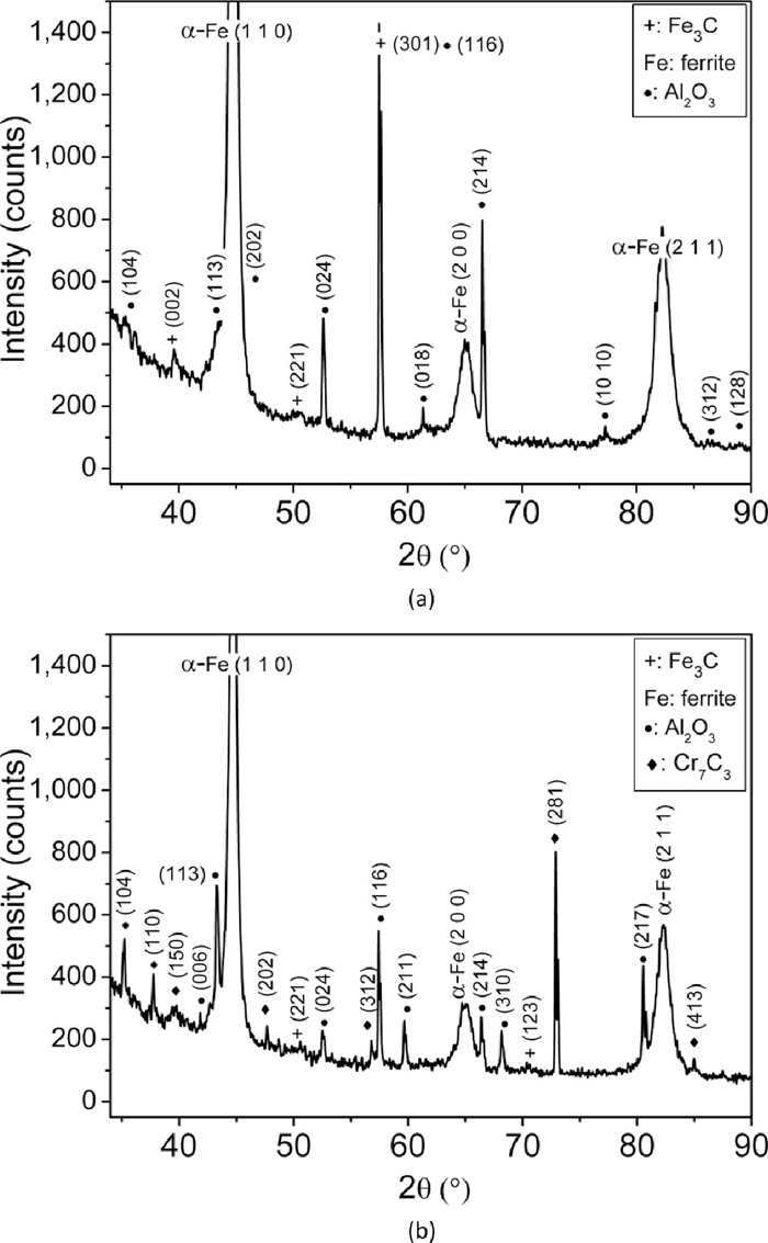
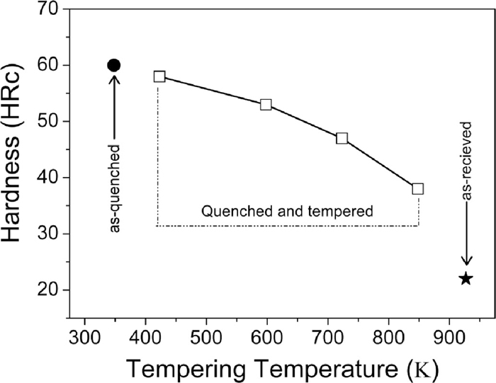
Figure 1 shows the hardness of as-quenched, quenched & tempered and as-received En31 steel. The as-received materials has the lowest hardness (22 HRc), while the as-quenched material has the highest hardness (60 HRc). After tempering at 423 K, the drop was insignificant (2 HRc). It has been reported that quenching from austenization temperature leads to a microstructure containing martensite, about 6 vol% of retained austenite and 3–4% of cementite particles which fail to dissolve during the austenizing treatment.1,30) When the steel is tempered at low temperatures (< 473 K) to relieve the internal stresses, retained austenite decomposes and precipitation of transition carbides of iron takes place from the supersaturated martensite.4) At temperatures in excess of 473 K, the material softens.4,30) In the present study, there is a gradual drop in hardness with the increase in tempering temperature from 423 K to 873 K. Such monotonous decrease in hardness with the increase in tempering temperature was also reported by Lee et al. and Leskovsek et al. for AISI 4340 and H11 tool steel respectively.31,32) This decrease in hardness with tempering temperature could be attributed to reduction in dislocation density and decomposition of martensite into ferrite and cementite. The secondary electron micrographs of the as-received, as-quenched and quenched + tempered En31 steel samples are shown in Fig. 2. The as-received (i.e. as-rolled and annealed – Fig. 2(a)) sample showed the presence of pearlite along with pro-eutectoid cementite network along the prior austenite grain boundaries. The approximate average interlamellar spacing of pearlite was observed to be about 0.5 μm. The morphology of the pearlite is related to the initial grain size of austenite during the heat treatment; coarser austenite leads to the formation of coarser pearlite and consequently larger interlamellar spacing. The microstructure of the as-received material was pearlite with pro-eutectoid grain boundary cementite with lower hardness of 22 HRc. The as-quenched structure (Fig. 2(b)) consisted of un-dissolved iron carbides and martensite. The inset in Fig. 2(b) shows the microstructure at higher magnification, which clearly reveals the martensitic structure and un-dissolved iron carbides. These results were also confirmed by XRD (see Fig. 3). The XRD pattern of the as-received sample (Fig. 3(a)) showed ferrite (α-Fe) and cementite (Fe3C) peaks. The Fe3C peaks were very low in intensity, in-spite of its greater proportion in the annealed structure due to the fact that the atomic scattering factor of carbon is very low as compared to Fe.33) The α-Fe peaks in the diffraction pattern were also very narrow, since the structure was completely in the annealed condition. The broadening of the X-ray peaks is related to the size and/or micro-strain present in the sample.33) Reduction in the size of the crystallites/domains and increase in the micro-strain leads to broadening of the X-ray peaks. The XRD pattern of the as-quenched sample (Fig. 3(b)) showed the presence of martensite, retained austenite and un-dissolved Fe3C. The martensite peaks were indexed as α-Fe peaks, since the resolution of the diffractometer at smaller 2θ angles was not sufficient to resolve the tetragonality of the martensite lattice.4,33) It has been reported4,10,34) that the alloying additions lower the martensitic start temperature (Ms). The role of alloying elements on the Ms temperature is given by the empirical relationship due to Andrew’s4,34) (concentration in weight%):
|
M
s
(K)=539-423(%C)-30.4(%Mn)
-17.7(%Ni)-12.1(%Cr)-7.5(%Mo)+273
| (1) |
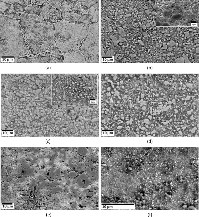
The Ms temperature obtained by using Andrew’s relationship (Eq. (1)) for the present En31 steel was found to be 356.36 K. If the steel is cooled sufficiently rapidly from the austenizing temperature, some amount of austenite is retained in the microstructure (usually known as retained austenite). The XRD pattern of the as-quenched steel (Fig. 3(b)) showed the presence of retained austenite (approximately 5–6%). It was observed that the retained austenite persists in the microstructure even after tempering at 598 K for 3600 s. It may be possible that the tempering time used was not sufficient to convert all the retained austenite into martensite. The diffraction peaks are also substantially broader in the as-quenched steel as compared to the as-received and quenched + tempered steel indicating the presence of large micro-strain (due to dislocations).10) This is typical for the as-quenched structure. An earlier investigation on En24 steel also reported the broadening of X-ray peaks due to presence of dislocations in the quenched microstructure.10) The broadening reduced after tempering the martensite. Figures 2(c) to 2(f) show the microstructures of tempered martensite in En31 steel. It can be observed from Figs. 2(c) to 2(e) that the un-dissolved carbides became coarser with increase in tempering temperature. Also there is precipitation of new finer carbides. The carbide morphology was different after tempering at 598 K and 848 K. Therefore, it was decided to use SEM-EDS for selected heat treatment conditions to investigate/substantiate the microstructures further. The microstructure after tempering at the highest temperature (848 K) was not resolved properly even after using FEG-SEM. Table 2 shows the SEM-EDS results for samples tempered at 598 K and 848 K, while Fig. 3(c) shows the XRD patterns for the quenched and 598 K tempered samples. It can be observed from Table 2 that the carbides after 598 K tempering were complex carbides. The composition was almost 50%Cr and 50%Fe. This also explains the different morphology of the carbides. XRD patterns (Fig. 3(c)) also substantiates the SEM-EDS results as these carbides were indexed to be of type Cr7C3. The carbides after 848 K tempering were predominantly iron carbides (Fe3C), which were slightly enriched with Cr and Si (see Table 2). The published data on the microstructural evolution during tempering of En31 steel is very limited. In Cr containing steels, two types of Cr carbides (Cr7C3 and Cr23C6) are often encountered and the normal carbide sequence during tempering is:35)
|
Matrix→
(FeCr)
3
C→
Cr
7
C
3
→
Cr
23
C
6
|
Table 2. Chemical composition of the carbides in the quenched and tempered condition as obtained by energy dispersive spectroscopy (in weight%).
| Tempering temperature | Cr | Fe | Si |
|---|
| 598 K | 52.48 | 47.52 | – |
| 848 K | 03.37 | 96.00 | 0.66 |
Table 3. Bulk hardness (HRc) of heat treated En31 steel samples.
| as- received | as- quenched | Quenched and tempered at 423 K | Quenched and tempered at 598 K | quenched and tempered at 723 K | Quenched and tempered at 848 K |
|---|
| 22 | 60 | 58 | 53 | 47 | 38 |
Cr23C6 precipitation does not occur until the Cr concentration in steel exceeds about 7%. The transformation of Fe3C to Cr7C3 occurs mainly by nucleation at the Fe3C/ferrite interfaces. Cr diffuses more rapidly in steels as compared to other alloying elements and hence Cr7C3 is detected during tempering even at temperature less than 773 K and it coarsens very rapidly (598 K tempering in the present case). The sluggish microstructure after tempering at 848 K and presence of Fe3C indicates the decomposition of martensite into ferrite and Fe3C (also confirmed by the SEM-EDS results – see Table 2).
3.2. Abrasive Wear Behaviour
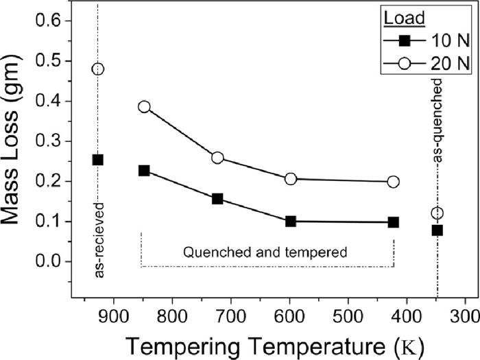
The mass loss (gm) during two body abrasive wear of En31 steel for as-quenched, quenched & tempered and as-received condition as a function of load is shown in Fig. 4. The as-quenched sample consisting of martensitic structure with un-dissolved iron carbides showed the lowest mass loss. The as-received sample consisting of pearlite and pro-eutectoid cementite showed highest mass loss, while the quenched + tempered samples showed intermediate mass loss. For quenched + tempered samples, there was a gradual increase in mass loss with the increase in tempering temperature. For all the heat treated conditions, increase in load from 10 N to 20 N caused a corresponding increase in the wear mass loss. As explained in section 3.1, after tempering at 598 K, the microstructure consisted of alloy carbides (Cr7C3) and after tempering at 848 K, the carbides were Fe3C. The wear mass loss seems to depend only on the hardness. Figure 5 shows the correlation of bulk hardness with the wear mass loss and load. It can be clearly seen from the Fig. 5 that the wear mass loss decreases with the increase in the hardness. The wear is much more pronounced at higher load (20 N) as compared to lower load (10 N) – about 1.85 times. The wear mass loss and hardness has a very good linear correlation at both the loads (the regression coefficients are greater than 0.90 in both the cases). The increase in the wear mass loss at higher load (20 N) could be attributed to the increased depth of cut by the abrasive particles on the surface of the specimen with increased load.12) The abrasive wear resistance of the heat treated samples was calculated by considering the annealed sample as reference. The abrasive wear resistance of the samples tempered at 423 K and 598 K was about 2.3–2.6 times when compared with the as-received sample, while it was 1.1–1.8 times for samples tempered at 723 K and 848 K. Similar observations were reported by many investigators in the past.36,37) In the present investigation, the tempering time was kept constant and tempering temperature was varied. It is possible that by keeping the tempering temperature constant and varying the time may result in different microstructural features/hardness and consequently different abrasive wear resistance.38) However, in the present investigation, the hardness seems to have a direct correlation with the abrasive wear resistance.

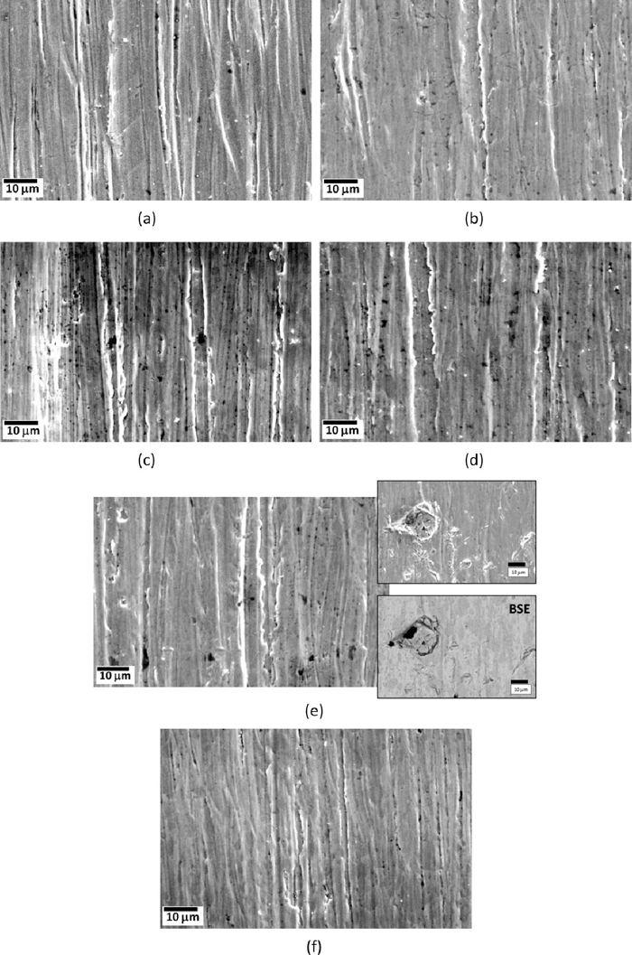
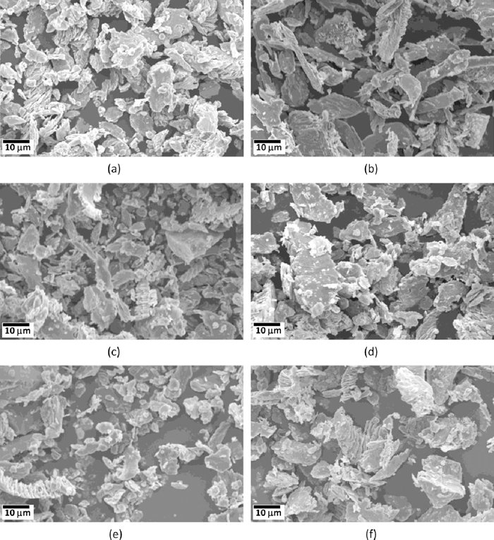
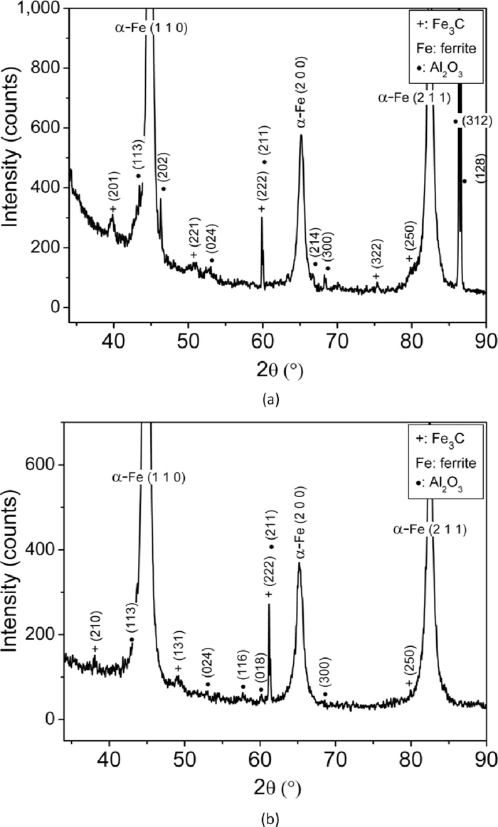
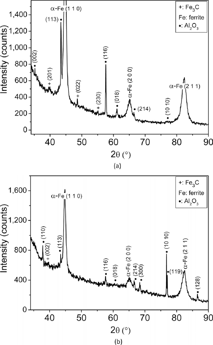
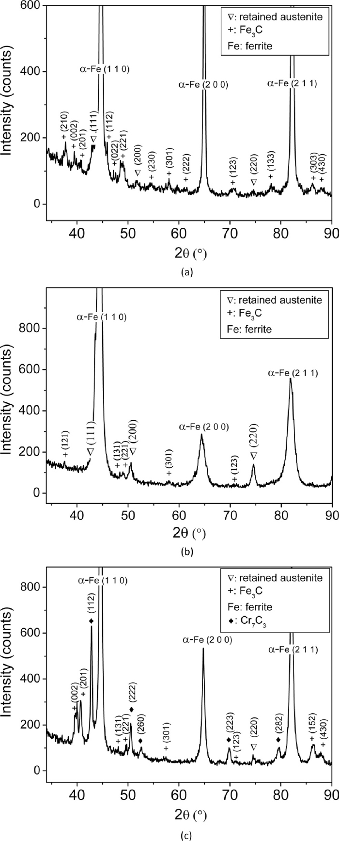
To find the micro-mechanisms of two body abrasive wear, SEM of worn surfaces (all conditions) and SEM & XRD of the wear debris (few selected conditions) was carried out. The SEM micrographs of worn out as-received, as-quenched and quenched + tempered En31 steel specimens at a load of 10 N are shown in Fig. 6. Figure 6(a) shows long deep grooves, which were formed as the abrasive particles plough across the surface and eventually removing or pushing material into ridges along sides of the grooves formed by Al2O3 abrasive particles.39,40) The abrasive particles being harder were able to cause deep plastic indentation in the annealed as-received material.41) If the ratio of hardness of abrasive particle to that of surface is more than 1.2 the abrasive particles were able to plastically indent the surface.14,42) The width and depth of the grooves was considerably large in the annealed sample (Fig. 6(a)) as compared to the as-quenched sample (Fig. 6(b)). There was no substantial difference in the morphology of abraded surfaces of as-quenched (Fig. 6(b)) and 423 K tempered sample (Fig. 6(c)). The width and depth of the grooves became progressively wider and deeper with the increase in tempering temperature. Figure 7 shows the worn out surface of heat treated En31 steel at a load of 20 N. In Fig. 7 (20 N load), the abraded surfaces have much deeper and wider grooves as compared to Fig. 6 (10 N load). With the increase in load the relative contribution of micro-cutting to total wear loss increases. These observations are consistent with the measured mass loss values (Figs. 4 and 5). The SEM micrographs of the wear debris of as-received, as-quenched and quenched + 598 K tempered samples are shown in Fig. 8 at both 10 N and 20 N loads. The wear debris particles in general exhibited flaky morphology. The wear debris particles were relatively finer at a load of 10 N and for the as-quenched heat treated condition as compared to other conditions. Figures 9, 10 and 11 show the XRD pattern of the wear debris for as-received, as-quenched and quenched + 598 K tempered samples at both the loads (10 N and 20 N). The XRD patterns did not show the presence of iron oxide peaks for any of the heat treated condition. This indicates that the wear mechanism was not oxidative at both the loads. For as-received and the as-quenched samples, the XRD pattern showed the presence of ferrite (or martensite), cementite and alumina (Al2O3). For the quenched + 598 K tempered sample, along with ferrite (or martensite), cementite and alumina (Al2O3) peaks, peaks of Cr7C3 were also present. This indicates that along with micro-cutting and micro-ploughing, pull out of carbide particles from the matrix also occurred during abrasive wear at 20 N load resulting in increased wear loss as compared to that at 10 N.

4. Conclusions
In the present study, the microstructures of En31 steel after hardening and tempering were analyzed and the effect of microstructures and bulk hardness on the two body abrasive wear behaviour was studied along with characterisation of worn out surfaces and wear debris particles.
The as-received microstructure of En31 steel consisted of pro-eutectoid ferrite along prior austenite grain boundaries and pearlite. Martensite was formed after hardening, while the un-dissolved cementite which remained after hardening coarsened after low temperature tempering (423 K). After tempering at 598 K, the microstructure consisted of alloy carbides (Cr7C3) along with tempered martensite. At higher tempering temperatures (848 K), the martensite decomposed to give ferrite and cementite. With increase in tempering temperature the morphology of the carbides became coarser. The two body abrasive wear resistance of heat treated En31 steel exhibited good correlation with bulk hardness; an increase in hardness increased the abrasive wear resistance. The important material removal mechanisms during abrasive wear were ploughing and cutting and pull out of carbides. The finer morphology of carbides was observed to be beneficial in increasing the abrasive wear resistance. The wear debris particles exhibited flaky morphology and were relatively finer at lower loads.
Acknowledgement
The authors would like to thank Director, VNIT Nagpur for providing necessary facilities for the present investigation and constant encouragement to publish this paper. The authors would like to acknowledge the use of “National Facility of Texture & OIM (a DST-IRPHA facility)” for SEM-EBSD-EDS measurements.
References
- 1) H. K. D. H. Bhadeshia: Prog. Mater. Sci., 57 (2012), 268.
- 2) E. N. Bamberger: Bearing Design – Historical Aspects, Present Technology and Future Problems, ASME, New York, (1980), 1.
- 3) J. Cappel, M. Wienberg and R. Flender: Steel Grips, 2 (2004), 261.
- 4) R. W. K. Honeycombe and H. K. D. H. Bhadeshia: Steels – Microstructure and Properties, Butterworth-Heinemann, Oxford, (1995).
- 5) M. F. Carlson, B. V. Narasimha and G. Thomas: Metall. Trans., 10A (1979), 1273.
- 6) D. H. Huang and G. Thomas: Metall. Trans., 2A (1971), 1587.
- 7) K. Holmberg and A. Mathews: Coatings, Tribology, Property, Techniques and Applications in Surface Engineering, Elsevier, Great Britain, (1994).
- 8) M. H. Shaeri, H. Saghafian and S. G. Shabestari: Mater. Design, 34 (2012), 192.
- 9) F. Katsuki, K. Watari, H. Tahira and M. Umino: Wear, 264 (2008), 331.
- 10) R. K. Khatirkar, P. Yadav and S. G. Sapate: ISIJ Int., 52 (2012), 1370.
- 11) A. Sundström, J. Rendon and M. Olsson: Wear, 250 (2001), 7441.
- 12) S. G. Sapate, A. D. Chopde, P. M. Nimbalkar and D. K. Chandrakar: Mater. Design, 29 (2008), 613.
- 13) W. Osterle, G. Nozle and P. X. Li: Mater. Sci. Eng. A, 262 (1999), 308.
- 14) I. M. Hutchings: Tribology: Friction and Wear of Engineering Materials, CRC Press, Arnold, London, (1992).
- 15) K. Luo and B. Bai: Mater. Design., 31 (2010), 2510.
- 16) E. Atik, U. Yunker and C. Meric: Tribo. Int., 36 (2003), 155.
- 17) S. G. Sapate, C. Gurijala, A. Ratho and A. Singh: Int. Conf. on Adv. Mech. Eng., IDES-CPS, New York, (2011).
- 18) J. Suchanek and V. Kuklik: Wear, 267 (2009), 2100.
- 19) Y. C. Lin, S. W. Wang and T. M. Cheng: J. Mater. Process. Technol., 120 (2002), 126.
- 20) A. Bahrami, S. H. Mousavi Anijdan, M. A. Golozar, M. Shamanian and V. Varahram: Wear, 258 (2005), 846.
- 21) G. H. Yang and W. M. Garrison, Jr.: , Wear, 129 (1989), 93.
- 22) I. Sevim and I. B. Eryurek: Mater. Design, 27 (2006), 173.
- 23) G. Balachandran, A. Vadiraj, M. Kamraj and E. Kazuya: Mater. Design, 32 (2011), 4042.
- 24) P. L. Hurricks: Wear, 26 (1973), 285.
- 25) A. K. Bhakat, A. K. Mishra and N. S. Mishra: Wear, 263 (2007), 228.
- 26) A. K. Jha, B. K. Prasad, O. P. Modi, S. Das and A. H. Yegneswaran: Wear, 254 (2003), 120.
- 27) X. Ma, R. Liu and D. Y. Li: Wear, 241 (2000), 79.
- 28) A. S. M. Handbbok: Metallography and Microstructures, Vol. 9, ASM International, OH, USA, (2004).
- 29) X’Pert Highscore: Version 2.1b (2.1.2), PANaltical B. V., The Netherlands, (2005).
- 30) G. R. Speich and W. C. Leslie: Metall. Trans. A, 3 (1972), 1043.
- 31) W. S. Lee and T. T. Su: J. Mater. Process. Technol., 87 (1999), 198.
- 32) V. Leskovšek, B. Sustarsic and G. Jutrisa: J. Mater. Process Technol., 178 (2006), 328.
- 33) B. D. Cuillity: Elements of X-ray Diffraction, Addison-Wesley Publishing Company, USA, (1978).
- 34) K. W. Andrews: J. Iron Steel Inst., 203 (1965), 271.
- 35) H. K. D. H. Bhadeshia and R. W. K. Honeycombe and Steels – Microstructure and Properties, Butterworth-Heinemann, Oxford, (2006).
- 36) M. A. Moore: Wear, 28 (1974), 59.
- 37) K. Ueda, N. Ishikawa and Y. Murota: Mater. Sci. Forum, 706–709 (2012), 2342.
- 38) Y. Sahin, M. Erdogan and M. Cerah: Wear, 265 (2008), 196.
- 39) W. M. Garrison, Jr.: , Wear, 114 (1987), 239.
- 40) W. M. Garrison, Jr. and R. A. Garriga: Wear, 85 (1983), 347.
- 41) M. M. Khruschov: Wear, 28 (1974), 69.
- 42) K. H. Zum Ghar: Microstructure and Wear of Materials, Elsevier, Amesterdam, (1987).