2014 Volume 54 Issue 1 Pages 1-8
2014 Volume 54 Issue 1 Pages 1-8
The effect of slag properties (thickness and viscosity), have been evaluated in terms of mixing time, exposed surface or ladle eye and energy dissipation. A nozzle configuration defined in terms of the number of nozzles, its radial position and gas flow rate has been employed to describe the influence of the top layer on mixing phenomena. It has been found a negative effect of both slag thickness and slag viscosity on mixing time, on the other hand, the same properties are useful to decrease the exposed surface or ladle eye.
An empirical approach using water modeling is suggested to evaluate the average velocity of the bulk liquid. The method was used to define the fraction of stirring energy consumed by the top layer. The result is in agreement with a previous investigation.
There are several ways to improve mixing in the bath; Induction stirring (ASEA-SKF process), bubble stirring (Ladle furnace process) and mechanical stirring (Kambara reactor). One advantage1) of induction stirring over argon stirring is the elimination of the spout and therefore minimization of steel reoxidation and improved efficiency of alloying elements, however, gas stirring provide higher stirring intensities, required in the desulphurization of liquid steel.2)
Argon injection is most commonly done with porous plugs located in the bottom of a ladle. In industrial ladles it is typical to have one or two porous plugs, depending on the size of the ladle. Its position is critical to achieve the expected benefits of thermal and chemical homogenization as well as a strong metal-slag interaction.3,4) In the past, a large amount of research has been conducted by physical and mathematical models to describe fluid flow in the ladle,5,6,7) however, the effect of the top slag layer has been incorporated only in few investigations.8,9,10,11,12) In this work, it is reported the effects of the top slag layer on mixing time, as a function of gas flow rate, number of nozzles and nozzle radial position.
An industrial size ladle of 140 tonnes of nominal capacity was used as prototype to design a physical model with a geometric scale factor 1:6. The dimensions of both prototype and physical model are indicated in Table 1. Air was injected through nozzles with a diameter of 8 mm. In order to evaluate the effect of nozzle radial position and number of nozzles, the arrangement shown in Fig. 1 was employed. Figure 2 shows the nozzle arrangement in the set of experiments. The experimental arrangement includes the possibility to evaluate the influence of 1 to 3 nozzles at different nozzle radial positions and three gas flow rates, with and without a top slag layer of 4 mm. Table 2 describes the variables included in the experimental work.
| Total height | Bath height | Diameter | |
|---|---|---|---|
| Prototype | 3736 | 2460 | 3226 |
| Water model | 622 | 410 | 537 |
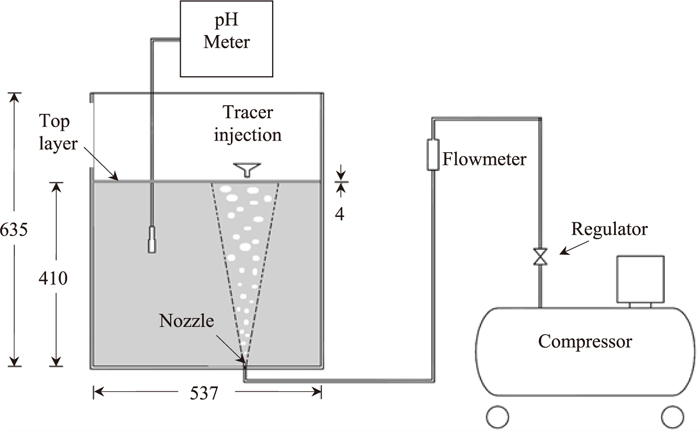
Experimental set-up.

Nozzle arrangement for the cases of 1, 2 and 3 nozzles.
| N | r/R | θ | Q (Nl/min) | hs, mm |
|---|---|---|---|---|
| 1 | 0, 0.33, 0.50, 0.67, 0.80 | – | 7, 17, 37 | 0,4 |
| 2 | 0.33, 0.50, 0.67 | 180° | 7, 17, 37 | 0,4 |
| 3 | 0.33, 0.67 | 120° | 7, 17, 37 | 0,4 |
The gas flow rate in the physical model was computed using the similarity criteria based on the modified Froude number. This criterion is expressed by the following relationship:
| (1) |
Where: Qm represents the gas flow rate in the water model, λ is the geometric scale factor, defined as the ratio of liquid heights (Hm/Hfs) and Qfs is the gas flow rate in the full-scale system.
The corresponding gas flow rate in the water model was defined in the range from 7–37 Nl/min. The term “low” gas flow rate is assigned to the value 7 Nl/min, “medium” for 17 Nl/min and “large” gas flow rate for 37 Nl/min.
Mixing time was measured using pH data. A pH meter model PC510 manufactured by Eutech was employed. In all experiments distilled water was employed with an approximate initial pH of 6.0. The alkalinity is increased to 10.0 by the addition of 10 ml of a solution of NaOH 1 M. To repeat the experiment, the initial pH was restored with additions of HCl 1 M. The tracer was added on the top of one of the spouts.
The position of the electrode was chosen at a point visually matching the periphery of the largest recirculating loop. Before tracer addition, air was injected to promote steady state conditions in the flow pattern. Mixing time was measured based on the criteria of 95% homogenization. Every set of experiments was repeated three times.
The top slag layer was simulated with oil. The standard experiments consisted of engine oil with a thickness (hs) of 4 mm, equivalent to 1% of the bath height. Its density is slightly below that of the density of liquid water and its kinematic viscosity is 200 times higher than water, which is similar to the slag/steel system. A group of experiments was chosen to evaluate the influence of both slag thickness and viscosity on mixing time and on the opening of the slag eye. Table 3 summarizes the physical properties of the oils employed in the experimental work.
| Density, kg/m3 | Viscosity, m2/s × 106 | |
|---|---|---|
| Steel, 1600°C | 7000 | 0.97 |
| Water at 20°C | 998.2 | 1.00 |
| Slag | 3000 | 60–120 |
| Engine oil (red) | 890 | 215 |
| Engine oil (blue) | 881 | 192 |
| Soybean oil | 919 | 60 |
This section reports the influence of the variables investigated (nozzle radial position and number of nozzles, gas flow rate and slag thickness) on mixing time, as well as the effect of slag physical properties on the opening of the slag eye. A procedure to compute the stirring energy consumed by the top slag layer is also suggested using the concentration signal as a function of time.
3.1. Effects of Process Variables on Mixing TimeFigures 3–4 show the effect of nozzle radial position on mixing time. Each plot shows three solid lines corresponding to each gas flow rate with slag (thickness of 4 mm) and other three dashed lines for each gas flow rate without slag. Figure 3 corresponds to experiments with a single nozzle and Fig. 4 for two nozzles. Mixing time values fell in the range from 30–100 seconds.
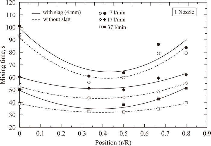
Effect of nozzle radial position on mixing time, for one nozzle at three different gas flow rates with and without a top slag layer.
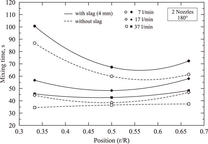
Effect of nozzle radial position on mixing time, for two nozzles at three different gas flow rates with and without a top slag layer.
Effect of slag thickness on mixing time: Figures 3–4 clearly indicate that the presence of a top slag layer always increases mixing time, independently of gas flow rate, radial position and number of nozzles, taking into account that the minimum stirring energy is in the order of 5 Watts/tonne. This effect is associated with a fraction of the total energy consumed in the motion of the top layer. The energy dissipated by the top slag layer is estimated in a subsequent section. Haida et al.13) and Ying et al.14) also reported experimental data for axisymmetrical gas injection and one single nozzle indicating an increase in mixing time in the presence of the top slag layer.
Effect of nozzle radial position: Figures 3–4 describe the influence of the nozzle radial position on mixing time. It can be seen that there is an overall minimum value in the cases of 1 and 2 nozzles. This minimum is identified, in general, at half radius, independently of slag thickness and gas flow rate. In the past, a large amount of investigations have been reported indicating different nozzle radial positions that yield the shortest mixing time.15,16,17,18,19,20,21,22,23) There is general agreement about the nozzle radial position, indicating half radius as the optimum value, however there are big discrepancies in regard with the separation angle. Joo and Guthrie15) as well as Zhang et al.17) suggest a separation angle of 180° with 2 nozzles, on the other hand, Jauhiainen et al.18) and Chen et al.22) suggest 60° and 45°, respectively. It should be noticed that only the work by Chen et al.22) reports mixing time in the presence of a top slag layer.
Effect of gas flow rate: The effect of gas flow rate (in terms of stirring energy) on mixing time is shown in Figs. 5–6 for the case of 1 nozzle located at different radial positions, with a top slag layer (Fig. 5) and without the top slag layer (Fig. 6). In both cases it is shown that mixing time decreases as stirring energy increases. This result is perfectly well known, however it is important to bear in mind that in order to minimize mixing time, the gas flow rate cannot be increased ad infinitum because as the gas flow rate increases it also increases the ladle eye (and therefore reoxidation becomes critical to the cleanliness of the steel), as well as a more severe erosion of the refractory walls.
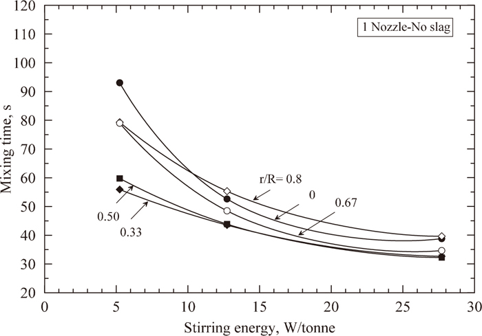
Relationship between stirring energy and mixing time for one nozzle without the top slag layer at different nozzle radial positions.

Relationship between stirring energy and mixing time for one nozzle with a top slag layer at different nozzle radial positions.
Effect of the number of nozzles: Figure 7 shows the effect of the number of nozzles on mixing time at three different nozzle radial positions (0.33R, 0.5R and 0.66R). All experimental gas flow rates are also included in this figure. Dotted and solid lines are accounted for cases with and without slag, respectively. At large or medium gas flow rates mixing time slightly increases with an increase in the number of nozzles. However, this increment is small and in some cases slightly decreases the mixing time with an increase in the number of nozzles. At low gas flow rates, there is an opposite behavior as the number of nozzles increases. At a nozzle radial position of 0.33R there is a maximum mixing time with two nozzles, however for the nozzle radial position of 0.66R there is a minimum mixing time with also two nozzles.

Effect of the number of nozzles (N) on mixing time at three different nozzle radial positions and three gas flow rates with and without the top slag layer.
It would be expected that by increasing the number of nozzles the number of circulation loops also increase. These circulation loops are independent from each other, therefore convective mass transfer is not allowed from one loop to the other. Only turbulent diffusion allows mass transfer from one loop to the other, then, by increasing the number of nozzles mixing could be negatively affected. This behavior could explain the experiments conducted at medium and large gas flow rates because mixing time increases with an increase in the number of nozzles. However, at low gas flow rates it seems that the combined effect of nozzle radial position, gas flow rate and number of nozzles makes more complicated to isolate the effect of the number of nozzles on mixing time.
The nozzle radial position makes the circulation loops to change its volume. If two nozzles are located near the center or near the wall, only one loop for each nozzle is created. At other intermediate positions, like 0.5R, two circulation loops for each nozzle are created. At a nozzle radial position of 0.5R, the volume of liquid in the circulation loops is uniform, in contrast to other nozzle radial positions where the volume in each circulation loop is different.
Zhu et al.23) as well as Ramirez-Argaez24) have previously described mixing time as a function of the number of nozzles, reporting an increase in mixing time as the number of nozzles increases. The following equations summarize their results:
| (2) |
| (3) |
Where: τ represents mixing time in seconds, is stirring energy in watts/kg, N is the number of nozzles, W represents mass in kg, Q is the gas flow rate in l/s, r/R is the nozzle radial position and H/D is the ratio between height to diameter of the bulk liquid.
General equation: a general equation summarizing the combined effects of the number of nozzles (N), specific energy input rate (ε) (difined by Mazumdar [6] and function of the gas flow rate, Q), nozzle radial position (r/R), and layer of slag in dimensionless way (hs/H, where hs is the thickness of oil in mm and H is the liquid depth in mm), was developed using the software Statgraphics with a correlation coefficient of 0.8. This correlation (Eq. (4)) express the mixing time as a function of universal variables that may be used to any system either physical models or industrial ladles and also includes the effect of the slag layer.
| (4) |
This equation indicates that mixing time decreases by decreasing the number of nozzles, decreasing the layer of slag, increasing the specific energy input rate (or the gas flow rate) and nozzle radial position. The gas flow rate trough the variable ε is the variable that influence the most on the mixing time promoting good mixing. On the contrary, the effect of the nozzle radial position and slag layer in this equation are less important due to the low value of those exponents (–0.0051 and 0.004 respectively). Figure 8 shows the relationship between predicted and experimental values. The exponent associated with the number of nozzles is small (0.1025), an indication that mixing time slightly increases with an increase in the number of nozzles.

Relationship between predicted and experimental values on mixing time.
The total input mechanical energy due to bottom gas injection is consumed by interaction with different zones of the liquid-top layer-wall system present in a ladle. Ideally it would be desirable that this energy should be consumed in the motion of the liquid phases (steel and slag), which includes gas-liquid interactions within the ascending plume, turbulent motion within the recirculation circuits, bulk phase-top layer interaction and slag surface motion. In addition to these mechanisms, spout formation and liquid-wall interaction complete the consumption mechanisms of stirring energy. These mechanisms are summarized in the following relationship:
| (5) |
Where: EPlume represents a fraction of the total energy consumed by the bubble-liquid interaction, ETRC represents the energy consumed by turbulent motion of the recirculation circuits, ESlag is the fraction of energy consumed by the top layer, ESurface includes the energy consumed by motion of the free surface as well as spout formation and EWall the fraction of energy consumed by the liquid-wall interaction.
Mazumdar and Guthrie25) reported values for the previous energy dissipation mechanisms, for the case of axisymmetric gas injection. Their analysis suggested that the top slag layer consumes approximately 9–19% stirring energy. The maximum value corresponds to conditions neglecting motion of the slag free surface and spout formation due to a very thick slag layer, in the order of 7% of slag height. In order to compute the energy dissipated by the top slag layer in the present work, using a procedure similar to that proposed by the previous authors, it is necessary to obtain data on the average speed of bath recirculation. In the following paragraphs a procedure to compute that velocity is proposed.
The concentration signal described in Figs. 9–10 was obtained by a proper selection of the electrode position. If the electrode is placed at a point outside of the main recirculation circuit, for instance in a dead zone, the concentration signal changes, corresponding to a diffusion dominant mechanism, represented by a continuous increment in concentration however if the position corresponds to a convective dominant mechanism, the concentration signal oscillates periodically. It was observed that the elapsed time between peaks in the concentration signal was relatively constant in each experiment. This time was associated with the time taken by the tracer to complete its motion along the circuit. If the circuit is assumed an ellipse, it is possible to estimate the average velocity using the concentration data as a function of time. In all cases, the tracer was added in one of the largest recirculation circuits.
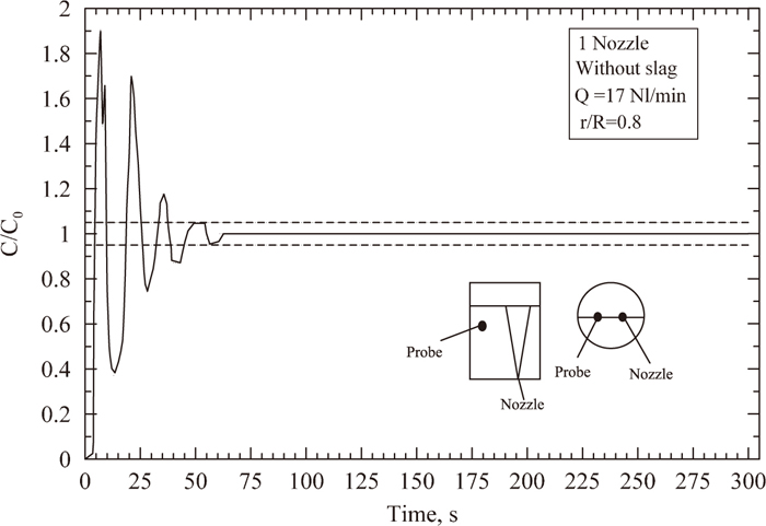
Concentration profile versus time for a gas flow rate of 17 Nl/min.
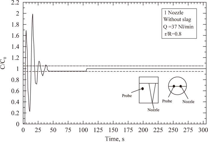
Concentration profile versus time for a gas flow rate of 37 Nl/min.
The average velocity is computed as follows:
| (6) |
Where;
In the procedure employed by Mazumdar and Guthrie25) the terms EPlume and ETRC were computed using the following expressions:
| (7) |
| (8) |
Where: Q is the gas flow rate corrected to mean height and temperature of the liquid in m3/s, H is the height of liquid in m, R is the radius of the vessel in m and
In the absence of the top slag layer and neglecting surface motion in experiments carried out with a wooden disk to represent the top layer, the previous authors computed the term EWall as follows:
| (9) |
The values for EWall were roughly estimated as 0.4. In order to compute the term ESurface, data from slag free experiments were used, obtaining values between 0.06 and 0.09. Finally, the previous authors computed the term ESlag for two limiting conditions, one corresponds to the presence of a thick slag layer and the other to a thin slag layer. In the first case, ESurface is set to zero and for the second case it was used an average value of 0.075. In such conditions, they reported values for ESlag in the range from 0.09–0.19.
Tables 4–5 report the results obtained in our work using the previous procedure and Fig. 11 is a schematic representation of the results for 1 nozzle at a position of 4/5 R. It can be observed that the energy dissipated by the top slag layer is in the range from 3–12%. Mazumdar and Guthrie25) reported slightly higher values, from 9–19%, however this is attributed to a large slag volume employed in their experiments. As the energy dissipation by the top slag layer increases, it is expected a decrease in the energy available to move the bulk liquid and a decrease in its average velocity. The data in Tables 4–5 indicate that a top slag layer of 4 mm decreases the average velocity of the bulk liquid from 15–30%, for example, for a gas flow rate of 7 Nl/min and one nozzle located in the center, the average velocity of the bulk liquid decreases from 64.5 to 45.5 mm/s. It is also observed that the values for energy dissipation from the free surface without a top slag layer range from 8–9%, similar to those of Mazumdar and Guthrie,25) who reported values in the range from 6–9%.
| Q m3/s ×104 |
| N | r/R | E W/kg | Computed values | |||
|---|---|---|---|---|---|---|---|---|
| ETRC | EPlume | ESurface | EWall | |||||
| 1.17 | 64.49 | 1 | 0 | 0.0052 | 0.20 | 0.34 | 0.09 | 0.37 |
| 2.83 | 88.95 | 1 | 0 | 0.0127 | 0.22 | 0.32 | 0.09 | 0.37 |
| 6.17 | 117.26 | 1 | 0 | 0.0276 | 0.24 | 0.29 | 0.09 | 0.38 |
| 1.17 | 63.86 | 1 | 1/3 | 0.0052 | 0.19 | 0.34 | 0.09 | 0.38 |
| 2.83 | 92.83 | 1 | 1/3 | 0.0127 | 0.26 | 0.32 | 0.08 | 0.34 |
| 6.17 | 124.82 | 1 | 1/3 | 0.0276 | 0.31 | 0.29 | 0.08 | 0.32 |
| 1.17 | 64.60 | 1 | 1/2 | 0.0052 | 0.20 | 0.34 | 0.09 | 0.37 |
| 2.83 | 88.61 | 1 | 1/2 | 0.0127 | 0.22 | 0.32 | 0.09 | 0.37 |
| 6.17 | 117.79 | 1 | 1/2 | 0.0276 | 0.24 | 0.29 | 0.09 | 0.37 |
| 1.17 | 65.14 | 1 | 2/3 | 0.0052 | 0.21 | 0.34 | 0.09 | 0.36 |
| 2.83 | 89.57 | 1 | 2/3 | 0.0127 | 0.23 | 0.32 | 0.09 | 0.37 |
| 6.17 | 119.43 | 1 | 2/3 | 0.0276 | 0.26 | 0.29 | 0.09 | 0.36 |
| 1.17 | 63.91 | 1 | 4/5 | 0.0052 | 0.19 | 0.34 | 0.09 | 0.38 |
| 2.83 | 89.87 | 1 | 4/5 | 0.0127 | 0.23 | 0.32 | 0.09 | 0.36 |
| 6.17 | 119.83 | 1 | 4/5 | 0.0276 | 0.26 | 0.29 | 0.09 | 0.36 |
| 1.17 | 65.02 | 2 | 1/3 | 0.0052 | 0.21 | 0.34 | 0.09 | 0.36 |
| 2.83 | 88.98 | 2 | 1/3 | 0.0127 | 0.22 | 0.32 | 0.09 | 0.37 |
| 6.17 | 120.75 | 2 | 1/3 | 0.0276 | 0.27 | 0.29 | 0.09 | 0.35 |
| 1.17 | 64.00 | 2 | 1/2 | 0.0052 | 0.19 | 0.34 | 0.09 | 0.37 |
| 0.83 | 88.89 | 2 | 1/2 | 0.0127 | 0.22 | 0.32 | 0.09 | 0.37 |
| 6.17 | 120.01 | 2 | 1/2 | 0.0276 | 0.26 | 0.29 | 0.09 | 0.36 |
| 1.17 | 63.56 | 2 | 2/3 | 0.0052 | 0.19 | 0.34 | 0.09 | 0.38 |
| 2.83 | 88.47 | 2 | 2/3 | 0.0127 | 0.22 | 0.32 | 0.09 | 0.38 |
| 6.17 | 118.91 | 2 | 2/3 | 0.0276 | 0.25 | 0.29 | 0.09 | 0.37 |
| 1.17 | 65.02 | 3 | 1/3 | 0.0052 | 0.21 | 0.34 | 0.09 | 0.36 |
| 2.83 | 88.05 | 3 | 1/3 | 0.0127 | 0.21 | 0.32 | 0.09 | 0.38 |
| 6.17 | 117.40 | 3 | 1/3 | 0.0276 | 0.24 | 0.29 | 0.09 | 0.38 |
| 1.17 | 64.63 | 3 | 2/3 | 0.0052 | 0.20 | 0.34 | 0.09 | 0.37 |
| 2.83 | 88.49 | 3 | 2/3 | 0.0127 | 0.22 | 0.32 | 0.09 | 0.38 |
| 6.17 | 116.20 | 3 | 2/3 | 0.0276 | 0.23 | 0.29 | 0.09 | 0.38 |
| Q m3/s ×104 |
mm/s | N | r/R | E W/kg | Computed values | ||||||
|---|---|---|---|---|---|---|---|---|---|---|---|
| ETRC | EPlume | ESurface | EWall | ESlag | |||||||
| min | max | min | max | ||||||||
| 1.17 | 45.52 | 1 | 0 | 0.0053 | 0.05 | 0.34 | 0 | 0.08 | 0.49 | 0.04 | 0.12 |
| 2.83 | 70.36 | 1 | 0 | 0.0128 | 0.09 | 0.32 | 0 | 0.08 | 0.48 | 0.04 | 0.12 |
| 6.17 | 99.22 | 1 | 0 | 0.0278 | 0.12 | 0.29 | 0 | 0.07 | 0.47 | 0.04 | 0.11 |
| 1.17 | 52.81 | 1 | 1/3 | 0.0053 | 0.09 | 0.34 | 0 | 0.07 | 0.46 | 0.04 | 0.11 |
| 2.83 | 73.82 | 1 | 1/3 | 0.0128 | 0.10 | 0.32 | 0 | 0.07 | 0.47 | 0.04 | 0.11 |
| 6.17 | 114.42 | 1 | 1/3 | 0.0278 | 0.21 | 0.29 | 0 | 0.08 | 0.40 | 0.02 | 0.10 |
| 1.17 | 52.70 | 1 | 1/2 | 0.0053 | 0.09 | 0.34 | 0 | 0.07 | 0.46 | 0.04 | 0.11 |
| 2.83 | 71.52 | 1 | 1/2 | 0.0128 | 0.09 | 0.32 | 0 | 0.08 | 0.48 | 0.04 | 0.12 |
| 6.17 | 100.12 | 1 | 1/2 | 0.0278 | 0.13 | 0.29 | 0 | 0.07 | 0.47 | 0.04 | 0.11 |
| 1.17 | 48.86 | 1 | 2/3 | 0.0053 | 0.07 | 0.34 | 0 | 0.08 | 0.48 | 0.04 | 0.12 |
| 2.83 | 74.13 | 1 | 2/3 | 0.0128 | 0.11 | 0.32 | 0 | 0.07 | 0.47 | 0.04 | 0.11 |
| 6.17 | 107.49 | 1 | 2/3 | 0.0278 | 0.17 | 0.29 | 0 | 0.08 | 0.43 | 0.03 | 0.11 |
| 1.17 | 57.52 | 1 | 4/5 | 0.0053 | 0.13 | 0.34 | 0 | 0.07 | 0.43 | 0.03 | 0.10 |
| 2.83 | 79.34 | 1 | 4/5 | 0.0128 | 0.14 | 0.32 | 0 | 0.08 | 0.44 | 0.03 | 0.11 |
| 6.17 | 106.52 | 1 | 4/5 | 0.0278 | 0.16 | 0.29 | 0 | 0.08 | 0.44 | 0.03 | 0.11 |
| 1.17 | 44.49 | 2 | 1/3 | 0.0053 | 0.04 | 0.34 | 0 | 0.08 | 0.49 | 0.04 | 0.12 |
| 2.83 | 67.62 | 2 | 1/3 | 0.0128 | 0.07 | 0.32 | 0 | 0.08 | 0.49 | 0.04 | 0.12 |
| 6.17 | 93.92 | 2 | 1/3 | 0.0278 | 0.10 | 0.29 | 0 | 0.08 | 0.49 | 0.04 | 0.12 |
| 1.17 | 50.53 | 2 | 1/2 | 0.0053 | 0.07 | 0.34 | 0 | 0.07 | 0.47 | 0.04 | 0.11 |
| 2.83 | 69.57 | 2 | 1/2 | 0.0128 | 0.08 | 0.32 | 0 | 0.08 | 0.49 | 0.04 | 0.12 |
| 6.17 | 91.43 | 2 | 1/2 | 0.0278 | 0.09 | 0.29 | 0 | 0.07 | 0.50 | 0.05 | 0.12 |
| 1.17 | 51.44 | 2 | 2/3 | 0.0053 | 0.08 | 0.34 | 0 | 0.07 | 0.47 | 0.04 | 0.11 |
| 2.83 | 70.44 | 2 | 2/3 | 0.0128 | 0.09 | 0.32 | 0 | 0.08 | 0.48 | 0.04 | 0.12 |
| 6.17 | 92.16 | 2 | 2/3 | 0.0278 | 0.09 | 0.29 | 0 | 0.07 | 0.50 | 0.05 | 0.12 |
| 1.17 | 51.23 | 3 | 1/3 | 0.0053 | 0.08 | 0.34 | 0 | 0.07 | 0.47 | 0.04 | 0.11 |
| 2.83 | 70.44 | 3 | 1/3 | 0.0128 | 0.09 | 0.32 | 0 | 0.08 | 0.48 | 0.04 | 0.12 |
| 6.17 | 93.92 | 3 | 1/3 | 0.0278 | 0.10 | 0.29 | 0 | 0.08 | 0.49 | 0.04 | 0.12 |
| 1.17 | 55.57 | 3 | 2/3 | 0.0053 | 0.11 | 0.34 | 0 | 0.08 | 0.44 | 0.03 | 0.11 |
| 2.83 | 76.27 | 3 | 2/3 | 0.0128 | 0.12 | 0.32 | 0 | 0.07 | 0.46 | 0.04 | 0.11 |
| 6.17 | 100.53 | 3 | 2/3 | 0.0278 | 0.13 | 0.29 | 0 | 0.07 | 0.47 | 0.04 | 0.11 |
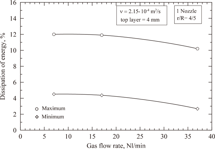
Effect of gas flow rate on the energy dissipated by the top slag layer.
In order to evaluate the effect of slag thickness and viscosity on mixing phenomena, three types of oils with different viscosities were chosen, as shown in Table 3. Two oils correspond to engine oils and a third one is soybean oil. Their viscosity ranges from 60–215 × 10–6 m2/s, which covers realistic viscosity ratios between slag and steel. The slag thickness was also changed from 4 to10 mm, equivalent to 1–2.5% of the total height.
Table 6 summarizes the results for the exposed surface or ladle eye as a function of gas flow rate for the case with an oil thickness of 4 mm and one nozzle placed at a nozzle radial position of 2/3 R. The surface area exposed or ladle eye was measured using a photographic and weighing method. In each experiment three photographs were taken in order to obtain an average value. The ladle eye in each photograph was cutted, weighed and finally expressed as a percentage. This process is accurate due to the high contrast in color between oil and water. The same results are illustrated in Fig. 12 which shows that as slag thickness increases, the exposed surface linearly increases. It also shows that as the slag viscosity increases, the exposed surface decreases. For the purpose of a faster refining process in the ladle furnace it is important to operate with relatively fluid slags. This type of slags are then more susceptible to increase the ladle eye for the same gas flow rate and therefore more susceptible to steel reoxidation.
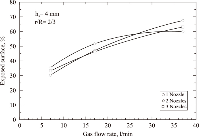
Effect of gas flow rate on the exposed surface for a top layer of 4 mm and nozzle radial position of 2/3 R.
Figure 13 shows the effect of slag thickness on ladle eye formation, for a configuration with one nozzle at a nozzle radial position of 1/3 R, a gas flow rate of 7 Nl/min and three different slag viscosities. The slag thickness was increased from 4 to 10 mm. It is quite clear that an increase in both slag thickness and viscosity decreases the exposed surface. A decrease of the exposed surface as slag thickness increases, was also reported by Yonezawa and Schwerdtfeger26) and by Maruyama and Iguchi.27) In the first case the system investigated was mercury-silicone oil and in the second case a water-polystyrene balls system.

Effect of slag thickness and slag viscosity on exposed surface, for 1 nozzle at a radial position of 1/3 R and gas flow rate of 7 l/min.
Figure 14 shows the effect of slag thickness on mixing time. It is shown that as the slag thickness increases, mixing time of the underlying phase also increases. This is due to an increase in the energy consumed by the top slag layer.

Effect of slag thickness and slag viscosity on mixing time.
Mixing phenomena becomes complex in the presence of multiple injection elements as a function of nozzle radial position, gas flow rate and the top slag layer. As the slag thickness increases, it also increases mixing time. This is due to higher energy dissipation as the slag thickness increases. Mixing times are also increased by decreasing the gas flow rate and increasing the number of nozzles.
A practical approach to measure the average recirculation velocity has been suggested. This method has been used to estimate the stirring energy consumed by the top slag layer. It has been found that the energy dissipated by the top layer ranges from 4–12%.
Ladle eye or exposed surface is decreased by an increase in slag viscosity. It also increases as gas flow rate increases, from approximately 30% for a gas flow rate of 7 l/min to 60% for 37 l/min.
It is not possible to clearly identify an optimum number of injection elements that provide the shortest mixing time because there is a combined effect between the number of nozzles, the gas flow rate and the nozzle radial position that makes difficult to indicate an optimum value of the number of injectors. However, the shortest value was found with one nozzle located at half radius.
Adrian Amaro thanks DGAPA-UNAM for financial support through a Ph.D. thesis scholarship.
a: Ellipse semi-major axis.
b: Ellipse semi-minor axis.
D: Diameter of the bulk liquid.
EPlume: Fraction of energy consumed by the bubble-liquid interaction.
ETRC: Fraction of energy consumed by turbulent motion of the recirculation circuits.
ESlag: Fraction of energy consumed by the top layer,
ESurface: Fraction of energy consumed by motion of the free surface as well as spout formation
EWall: Fraction of energy consumed by liquid-wall interaction.
hs: Thickness of oil layer
H: Height of the bulk liquid
N: Number of nozzles,
Q: Gas flow rate in l/s,
Qm: Gas flow rate in the water model,
Qfs: Gas flow rate in the full-scale system
R: Radius of the vessel in m.
r/R: Nozzle radial position
W: Mass in kg.
Greek symbols:λ: Geometric scale factor.
τ: Mixing time in seconds.
ε: Stirring energy in watts/kg.