Abstract
A new post tensioned column base connection for earthquake resistant steel moment resisting frames (MRFs) is introduced. The proposed post tensioned column base consists of high strength PT bars, reinforcing plate and bolted T-stubs. In this connection, the PT bars provide restoring force for self-centering behavior while the T-stubs dissipate energy by yielding. By using this connection, the plastic hinge in the column bases is removed and plastic deformation is concentrated in energy dissipation device. An analytical model based on fibre elements was developed with OpenSees to model column base connection. Accordingly; the model accurately predicts the expected behavior of the new proposed column base connection under cyclic loading. The proposed connection provides similar characteristic behavior of the post tensioned column base. To investigate the cyclic behavior of the PT column base connections, a series of the PT column base connection were subjected to axial load and cyclic lateral displacements. Analysis variables included PT bar diameter, initial post tensioning force and dissipation device size. Results showed that under large earthquake rotations, this connection could reduce or eliminate the plastic rotation by its self-centering behavior as well as providing required strength and stiffness.
1. Introduction
Post tensioned energy dissipation (PTED) beam-to-column connections are conceived as a suitable alternative to welded rigid connections for steel MRFs. They are aimed at guaranteeing a ductile and stable behavior during severe earthquakes, together with both self-centering and energy dissipation capabilities, resulting in a flag-shaped cyclic behavior. The PTED connection behavior is self-centering without residual deformations, so that no residual drifts are expected in a PTED-equipped moment resisting frame. The main structural elements, namely the beams and the columns, remain essentially elastic and the damage is confined to dissipater devices located in the connection, which are devoted to the dissipation of the input energy.
Up to now, several types of beam-to-column and column base connections have been proposed for the reliable implementation of the PTED (Post-Tensioned Energy Dissipater) concept in steel moment resisting frames. The main differences among the proposed systems lie in the technological solutions conceived for the PT and ED systems. In particular, the proposed PT systems are based on the use of high resistant steel strands or bars, whereas the proposed ED systems are based on yielding or friction mechanisms.1,2,3,4,5,6,7,8,9,10) Ricles et al.1,2) developed a self-centering beam-to-column connection system in which the PT system is based on a series of high resistance steel strands whereas the ED system is composed by bolted steel top-and-seat angles. The dissipative mechanism is based on the formation of three cylindrical plastic hinges at each angle, one next to the column bolt washers and two in the angle fillet. The main parameter considered in this study was the angle geometry. The tests have evidenced that the shim and reinforcing plates are necessary to control the inelastic deformation of the beams, that the size and geometry of the angles influence the connection moment capacity and the energy dissipation capacity, and that the strands must be designed to remain elastic in order to assure the self-centering and load carrying capability of the system.1,2) Garlock et al. experimentally investigated six steel beam-column joint sub-assemblies with PT connections similar to Ricles’s PT connection.3) Garlock et al. also proposed a design procedure for Special Moment Resisting Frame (SMRF) with posttensioned connections.4) Christopoulos et al., have studied a Self-Centering (SC) connection in which the PT system is based on a couple of high resistant steel bars, whereas the ED system is made of steel bars threaded in steel couplers and placed into steel confining cylinders. Both couplers and confining cylinders are welded to the beam flanges and to the continuity plates of the column.5) Several PTED connection systems, based on differently arranged friction devices, have been proposed and studied up to today. Kurama and Morgen studied the effect of the friction devices on the energy dissipation of the post-tensioned frames.6) Rojas et al. proposed a PTED connection in SC frames (PFDC).7) The proposed system was made of high resistance steel strands, whereas the ED system was based on friction devices. Friction devices were located at the top and bottom of the beam ends, and they dissipated the input energy during the cyclic gap openings. The proposed system had been studied by means of an analytical model based on fibre elements. The results showed, the seismic performance of the frames with PFDC, proved to be satisfactory in terms of strength, storey drift, local deformation and self-centering capability.7) Wolski et al. introduced a PTED connection type with high resistant steel strands, as PT strand, but ED system composed of friction devices placed only below the beam bottom flange (BFFD). The performed experimental studies have shown the excellent energy dissipation provided by the connection, together with the full self-centering properties.8) In the connection type conceived by Tsai et al. the PT arrangement is composed of high resistant steel strands, whereas bolted web friction devices work as ED system.9) Cyclic uni-axial tests on isolated bolted web friction devices and full-scale tests on beam-to-column assemblages equipped with the proposed system have been carried out. The obtained results confirmed the self-centering properties of the proposed connection, together with a very stable cyclic behavior, without stiffness and strength degradation.9)
Recently, Chi et al. proposed a post tensioned column base connection in the steel frame. The PT column base connection consists of high strength bars that are post-tensioned and buckling restrained steel (BRS) plates. To investigate the cyclic behavior of the PT column base connections, a series of the PT column base connection subassemblies were subjected to axial load and cyclic lateral displacements. Main findings include: (1) the column returns to its original position without residual deformation and (2) the BRS plates dissipate energy by yielding in tension and compression.10)
The column bases in the SC-MRF (self-centering moment resisting frame) may suffer damage (e.g., plastic hinging) for a major earthquake. This damage results in permanent residual deformations of columns affecting the self-centering capability of the SC-MRF system. To eliminate the structural damage in columns as well as to enhance the self-centering behavior of the SC-MRF, in this paper, a PT column base connection is introduced for use at column bases. The advantages of an SC-MRF with the PT column base connections include: (1) elimination of structural damage at beam-column connections and column bases for a major earthquake, (2) elimination of residual rotation due to earthquakes. Also this new connection can be used for retrofit and enhancement of existing non sufficient connection.
The proposed column base connection consists of high strength posttensioned bars, Reinforcing plates and bolted T-stubs. The PT bars provide restoring force for self-centering behavior while the T-stubs dissipate energy by yielding. This new connection requires no field welding. According to the common shape of the connection in the construction practice, the proposed connection has easy fabrication process. It is expected that the connection minimizes inelastic deformation. The self-centering behavior of the new connection is studied using the OpenSees program based on fiber elements. To verify the OpenSees models, the results are compared to the existing experimental results that conducted by Chi. Consequently, a detailed parametric study is performed by the verified models to study the self-centering behavior of the column base connection with different parameters such as, post tensioning bar size, initial post tensioning force and the size of energy dissipation device (T-stubs).
2. Introduction of Post Tensioned Column Bases
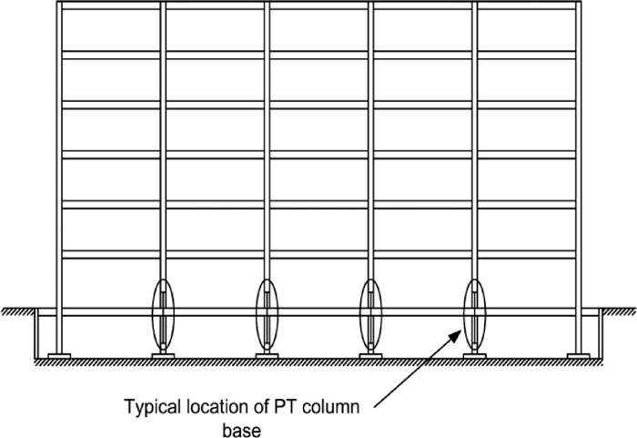
The new PT connection consists of high strength post tension bars, T-stubs and Reinforcing plates. Columns and grade beams are clamped by post-tensioning of the PT bars. The PT bars are anchored between the first story column and basement column. The layout of the location of the PT bars in the posttensioned column base is shown in Fig. 1. The proposed post tension column base connection is presented in Figs. 2 and 3. The PT bars provide clamping force to connect columns and beams, and restoring force to close the gaps occurring at the interface of the column and grade beam. T-stubs provide energy dissipation by yielding with plastic hinges. Damage in the PT column base connection occurs only in the T-stubs. If needed, the damaged T-stubs can be easily replaced. The T-stubs are bolted to the columns and grade beams. Reinforcing plates provide additional contact area during gap opening. Therefore, bearing stresses in the column flanges can be reduced for strong and weak axis bending.
3. Flexural Behavior of PT Column Base Connection
Figure 4 shows the idealized expected moment-rotation behavior of the new post tension column base connection. The moment-relative rotation response of the proposed PT column base connection is evaluated by gap opening and closing at the column-grade beam interface. When the column moment at column bases overcomes the moment resistance provided by initial PT force and axial force in columns, the connection decompresses, or a gap opening at column-grade beam interface (Δgap_col) begins to occur. The corresponding moment is defined as the decompression moment at the column base (Md–col). Point (1) in Fig. 4 corresponds the decompression moment. Before decompression, the initial stiffness of this connection is similar to the fully restrained moment connection.
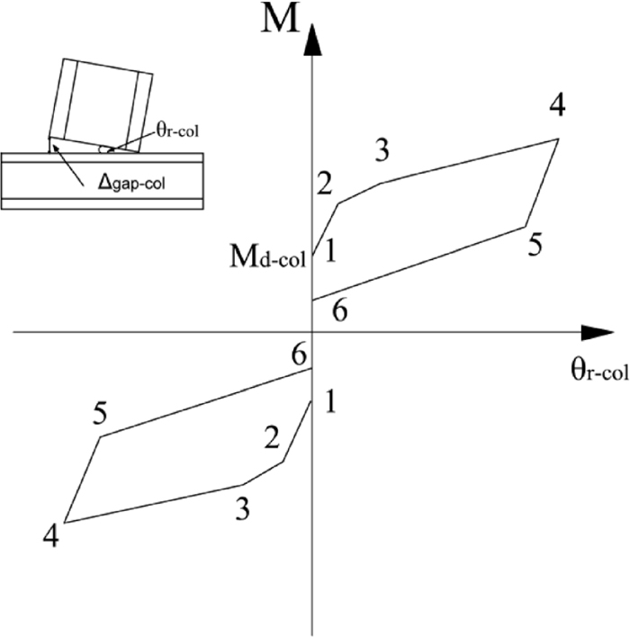
After decompression the column rotates about the contact surface in column flanges that creating relative rotation (θr_col) at the interface between column and grade beam. Then, additional axial force from the T-stubs and PT bars provided additional moment resistance in the post tension column base connection. After decompression, the stiffness of this new connection is related to the elastic stiffness of the T-stubs (kT–stub–i) and the axial stiffness of the post tension bars (Kbar). With continued loading, the tension T-stub begin to yield at point (2). After the T-stubs form a plastic yielding zone (point (3)), the stiffness of the connection depends mostly on the axial stiffness of the PT bars. Upon unloading at point 4, the T-stub will dissipate energy between point 4 and 6 and the gap (θr_col) is closed at point 6. The connection behavior is similar in the opposite direction according to Fig. 4.
4. Force-Deformation Relation of T-stubs
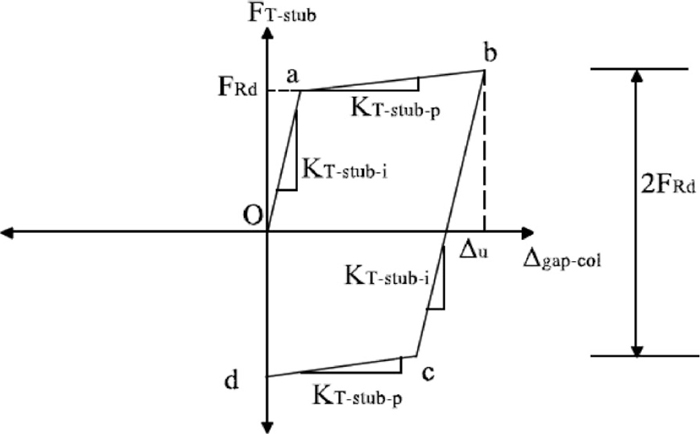
The T-stubs contributes the moment of the PT column base connection by forming plastic hinges. The force-deformation relation of the T-stubs is presented in Fig. 5. The T-stubs undergoes yielding and plastic hardening under cyclic loading. In order to determine the moment contribution of the T-stubs, it is necessary to estimate the axial stiffness and strength of the T-stub under cyclic loading. The force-deformation relation of the tension T-stubs under cyclic loading is assumed to be bilinear (i.e., path o-a-b-c-d in Fig. 5). When the applied moment overcomes the decompression moment of the connection, a gap opening occurs and the T-stubs develop a tension force. As the moment increases, the T-stubs yield in tension at point (a). After point (a), plastic yielding occurs and the hardening behavior of the T-stubs begins. When unloaded, the stiffness of the T-stubs is same as the elastic stiffness. Also, it is assumed that the yielding stress in compression (point (c)) is smaller than that of the initial yielding stress in tension (point (a)) due to the Bauschinger effect. Kinematic hardening is employed to determine the cyclic hardening behavior of the T-stubs.
The force-deformation relation of the T-stubs is evaluated according to Euro code 3. The initial elastic stiffness of T-stub is obtained from Euro code 3. The initial elastic stiffness of the two T-stubs connected by bolts (KT–stub–i) is equal to following equation:11)
|
K
T–stub–i
=
1
1
k
b
+
1
k
T1
+
1
k
T2
| (1) |
Where; k
T1, k
T2 are initial stiffness of each T-stubs and k
b is initial stiffness of bolt.
|
k
T1
=0.85
2
L
eff
t
f
3
m
3
(
3m+n
)
(
3m+4n
)
| (2) |
If (n=1.25 m) then
|
k
T2
=0.85
L
eff
t
f
3
m
3
| (3) |
L
b (Bolt length); is defined based on EC3:
11)
|
L
b
=
t
f1
+
t
f2
+2
t
w
+1/2(
t
h
+
t
n
)
| (5) |
Where; A
s: tensile stress area of a bolt and
th,
tn and
tw; the thicknesses of the bolt head, the nut and the washer, respectively.
tf1 and
tf2 are the flange thickness of each T-stub. L
eff is effective length. Finally m: is distance between the flange-to-web plastic hinge and the bolt axis on the flange, and n: is, distance between the location of the bolt axis and the tip of the flange(n≤ 1.25 m).
4.2. Yield Force of T-stubs
The T-stub has three failure modes, corresponding to the different resistances as follows:11)
Mode 1, flange yielding:
|
F
T,1,Rd
=
4
M
pl,Rd
m
| (6) |
|
M
pl,Rd
=0.25
t
f
2
f
y
b
eff
| (7) |
|
b
eff
=min{
2πm,b,4m+1.25n
}
| (8) |
Mode 2, bolt failure with flange yielding
|
F
T,2,Rd
=
2
M
pl,Rd
+n
∑
B
t,Rd
m+n
| (9) |
Mode 3, bolt failure:
|
F
T,3,Rd
=
∑
B
t,Rd
| (10) |
Where, M
pl,Rd is the plastic moment resistance of the flange in bending, B
t,Rd is the resistance of the bolts in tension, b is the width of T-stub, t
f is the flange thickness of the T-stubs and f
y is yielding stress of the T-stub flange. The yield force of the T-stubs (F
Rd) in the force-deformation curve (corresponds to the point (a) can be estimated from
Eqs. (6),
(9) and
(10). The designer should consider the prying forces that develop in the column bolts so that bolt fracture does not occur. Hence for post tensioning connection design, only mode 1 is acceptable because bolt failure is not acceptable.
4.3. Inelastic Stiffness of T-stubs
The inelastic stiffness of the T-stubs can be estimated by:
|
K
T–stub–p
=
E
h
/
EK
T–stub–i
| (11) |
Where, E
h is strain hardening modulus and E is modulus of elasticity.
4.4. Ultimate Force of T-stubs
The ultimate force of the T-stubs (FT–stub–u) in the force-deformation curve can be estimated from Eqs. (6), (9) and (10), by replacing the plastic condition with the ultimate condition. Therefore Mpl,Rd and Bt,Rd was replaced by Mu and Bu respectively.11)
|
M
u
=0.25
t
f
2
f
u.f
b
eff
| (12) |
and
Where f
u.f: ultimate stress of the T-stub flange, and f
u.b: ultimate stress of the bolt material.
4.5. Ultimate Deformation of the T-stubs
The ultimate deformation of the T-stubs (ΔT–stub–u) can be estimated from following equation that obtained from force-deformation plot of T-stub (Fig. 5):
|
Δ
u
=
F
Rd
K
T–stub–i
+(
F
u
–
F
Rd
)
/
K
T–stub–p
| (14) |
5. Connection Moment
Point (1) in Fig. 4 represents the event where the connection decompressed. The decompression moment is10)
|
M
1
=
T
i
d
2–col
+
P
i
d
2–col
| (15) |
where, P
i: Initial axial force in column, T
j: Initial posttensioning force after jacking loss, d
2–col: Distance between centroid and center of rotation (COR) of the column before decompression (
Fig. 6). Point (2) marks the beginning of the yielding of T-stubs. This moment is calculated from
Eq. (16):
|
M
2
=
M
y
i–PTforce
+
M
y
T–stub
+
M
y
axial
+
M
y
PT
| (16) |
Chi suggested
Eqs. (17),
(18) and
(19), for M
i–PTforce, M
axial and M
PT10)
|
M
y
i–PTforce
=
T
i
(
d
2–col
–
h
anchor
sin(
θ
y
))
| (17) |
|
M
y
axial
=
P
i
(
d
2–col
–
h
col
sin(
θ
y
))
| (18) |
|
M
y
PT
=
K
PT
(
d
2–col
–
h
anchor
sin(
θ
y
))
2
θ
y
| (19) |
M
yT–stub is calculated from
Eq. (20).
|
M
y
T–stub
=
F
Rd
d
3–col
| (20) |
Where F
Rd was presented in
Eqs. (6),
(9) and
(10) according to Euro code 3 and
θy is the relative rotation that T-stubs yield.
d2–col (PT): Distance between COR and the resultant of initial PT force after decompression (Fig. 6), d2–col (axial): The distance between the COR and the acting line of the resultant of axial force after decompression, d3–col: Distance between COR and centerline of the tension T-stub, FRd: T-stub yielding force, hanchor: Distance between the column-grade beam interface and top anchorage of PT bar, hcol: Clear height of first story column and KPT: stiffness of posttensioning bars.
T-stubs reach the plastic strength at point (3). This moment correspond to point (3) is equal to;
|
M
3
=
M
p
i–PTforce
+
M
p
T–stub
+
M
p
axial
+
M
p
PT
| (21) |
The M
pi–PTforce, M
paxial and M
pPT is achieved from
Eqs. (17),
(18) and
(19) with replacing
θy with
θp and M
pT–stub is equal to:
|
M
p
T–stub
=
F
Rd
d
3–col
+
K
T–stub–p
(
θ
T–stub–p
d
3–col
–
F
Rd
K
T–stub–i
)
d
3–col
| (22) |
Chi suggested a rotation (0.04) for MCE, therefore M
4 that corresponding to the point (4) in
Fig. 4, is obtained from
Eq. (21), with replacing
θp with 0.04. Finally
|
M
5
=
M
4
–2
M
y
T–stub
| (23) |
|
M
6
=
M
1
–
M
y
T–stub
| (24) |
5. Approaches for Numerical Simulation
Numerical simulation of the post-tensioned (PT) column base connection was investigated in this paper, using the OpenSees program, Open System for Earthquake Engineering Simulation.12) Each structural member, e.g., T-stub (dissipater), column, and beam, is modelled by using various elements with specified material properties (see Fig. 7). The beam and column are modelled by using linear beam/column elements. Zero-length elements are used to model the gap opening/closing behavior, and these elements were assigned only to bear compression forces without rotation stiffness. Elastic-No Tension (ENT) material was used for gap opening/closing behavior.

The energy dissipation elements, which in the case of this study are T-stubs, are truss elements with an elastic-plastic material given an initial stiffness, hardening ratio and yield stress. STEEL02 material was assigned to energy dissipation elements for simulate the T-stubs behavior. This material is one of the default hysteretic materials in OpenSees Command Language Manual. The Steel02 material is based on Gioffre-menegotto-Pinto constitutive model. The model has a bilinear backbone carve with a post-yield stiffness expressed as a proportion of the initial modulus of elasticity of the steel. The model accounts for the Bauschinger effect, with contributes to the gradual stiffness degradation of members under cyclic response. This model has an isotropic hardening option of the hysteresis.12) The PT bars are also modelled with the nonlinear spring element with Elastic-Perfectly Plastic Material. The stiffness and strength of the spring element is determined with the material property (i.e., modulus of elasticity and yield stress) and cross-sectional area of the PT bar. To model the beam and column depth, rigid-links are modelled between the zero-length elements and the nodes of column/beam elements. The analysis steps were as follows: (1) pre stress was applied in the PT bar elements, (2) a point load (i.e., axial load) was applied to the top of column and (3) cyclic displacement was imposed to the top node of the column as shown in Fig. 7.
6. Verification of the PT Column Base Model
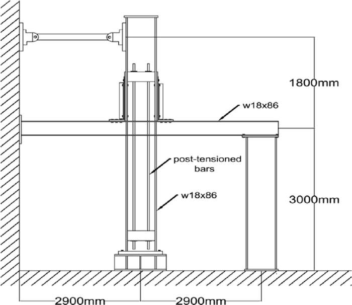
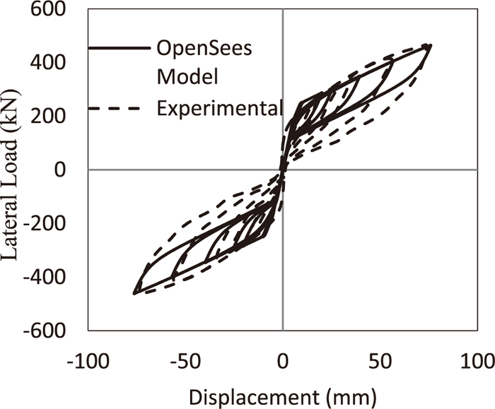
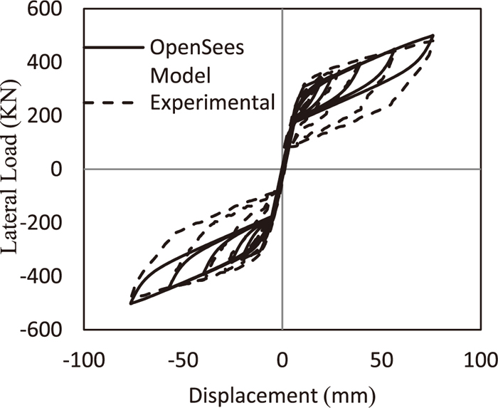
In order to verify the PT column base connection subassembly model, analysis results from the analytical models of OpenSees are compared to the experimental results for the PT column base connection subassemblies conducted by the Chi.10) The Connection details and test setup are shown in Figs. 8 and 9 respectively. Dimensions, sizes and detailed properties of the test specimens are tabulated in Table 1. This connection consists of high strength PT bars (Dywidag bars), reinforcing plates, buckling restrained steel (BRS) plates, shim plates and Keeper plates.10) BRS plates provide energy dissipation by yielding of the reduced section in tension and compression. The BRS plate and Keeper plate are shown in Fig. 8. The BRS plate and Keeper plate are welded by complete joint penetration (CJP) welding to form one unit. Damage in the PT column base connection occurs only in the BRS plates. The BRS and Keeper plates are bolted to the columns and grade beams. T-shaped cover plates are used to prevent buckling of the BRS plates. Reinforcing plates provide additional contact area during gap opening. The Keeper plates are bolted to grade beam flanges by slip critical bolting. The lateral displacement was applied according to the AISC loading protocol (Table 2).13) The PT bars remained elastic after the test. The hot rolled thread bars have a yield plateau, and the corresponding stress is around 830 N/mm2. The modulus of elasticity is 2.1 × 10⁵ N/mm2. The lateral load-displacement plots for specimen PTC-1A and PTC2 are shown in Figs. 10 and 11, respectively. As seen in Figs. 10 and 11, the OpenSees model response matches with the experimental results. The model, however, underestimates the size of the hysteretic loop.

Table 1. Test matrix.
10)| Test | & Beam Column | Initial Axial Force in Column (kN) | Initial posttensioning force (kN) | Loading history |
|---|
| PTC-1 | W18×86 | 587 | 836 | AISC |
| PTC-1A | W18×86 | 587 | 681 | AISC |
| PTC-1C | W18×86 | 267 | 1228 | AISC |
| PTC-1D | W18×86 | 587 | 1357 | AISC |
| PTC-1E | W18×86 | 587 | 703 | AISC |
| PTC-1F | W18×86 | 587 | 703 | AISC |
Table 2. Details of the cyclic loading according to AISC standard.
13)| Load step | Displacement of Column (mm) | Story Drift |
|---|
| 6 | 6.858 | 0.00375 |
| 6 | 9.144 | 0.005 |
| 6 | 13.716 | 0.0075 |
| 4 | 18.288 | 0.01 |
| 2 | 27.432 | 0.015 |
| 2 | 36.576 | 0.02 |
| 2 | 54.864 | 0.03 |
| 2 | 73.152 | 0.04 |
7. Parametric Studies and Seismic Behavior of the Column Base Connection
In this section the evaluation of the seismic behavior of the proposed post tension column base connection is presented with OpenSees program. To investigate the self-centering behavior and the effect of the connection details included, size of T-stubs, size of PT bar and initial posttensioning force on the behavior of the post tensioned column bases, analyses of the posttensioned column base connections listed in Table 3 were conducted. Each model is a post tensioned column bases sub assemblage that simulated an interior joint in a MRF. As is shown in Table 2, the AISC standard loadings are applied to the specimens.13) The beams and columns for analyses are selected similar to Chi’s design procedure.10) The size of beams and columns were presented in Table 3. The nominal yield strength (σy) for beams and columns was 345 MPa. All columns had a height of 4800 mm. The combined length of the specimens equal to the length of the two beams plus the column depth was 5800 mm according to Chi’s setup according to the Fig. 9. The force-deformation behavior of T-stubs is presented in Table 4. The modulus of elasticity of PT bars was 2 × 10⁵ N/mm2. The yielding stress of the bars begins 827.3 N/mm2.10) Results showed, the posttension column base model (Opensees model) estimated reasonable the connection behavior correctly. The analysis results showed that the proposed column base with PT bars was able to return to its original position without structural damage in beams and columns after cyclic loading (Figs. 12, 13, 14, 15, 16, 17, and 18).
Table 3. Specimens for analytical model and Results of analysis.
| Number | Initial PT force (kN) | Diameter of PT bar (mm) | Type of T-stub | Axial force in Column (kN) | T0/Tu | Md (kN-m) | Md/Mpn | Tmax/Tu | Mmax/Mpn | Loading |
|---|
| S1 | 614 | 30 | 1 | 587 | 0.2 | 276.23 | 0.23 | 0.51 | 0.52 | AISC |
| S2 | 614 | 35 | 1 | 587 | 0.14 | 276.23 | 0.23 | 0.46 | 0.57 | AISC |
| S3 | 614 | 40 | 1 | 587 | 0.11 | 276.23 | 0.23 | 0.41 | 0.63 | AISC |
| S4 | 614 | 45 | 1 | 587 | 0.09 | 276.23 | 0.23 | 0.35 | 0.67 | AISC |
| S5 | 614 | 50 | 1 | 587 | 0.072 | 276.23 | 0.23 | 0.3 | 0.7 | AISC |
| S6 | 900 | 30 | 1 | 587 | 0.3 | 345.43 | 0.32 | 0.6 | 0.64 | AISC |
| S7 | 1220 | 30 | 1 | 587 | 0.4 | 415.5 | 0.39 | 0.7 | 0.7 | AISC |
| S8 | 1525 | 30 | 1 | 587 | 0.5 | 485.7 | 0.46 | 0.78 | 0.74 | AISC |
| S9 | 1830 | 30 | 1 | 587 | 0.6 | 555.84 | 0.52 | 0.84 | 0.78 | AISC |
| S10 | 1525 | 30 | 2 | 587 | 0.5 | 485.7 | 0.46 | 0.78 | 0.8 | AISC |
Beam and Column: W18×86:
Table 4. T-stubs properties.
| Type of T-stubs | KT–stub–i
(kN/mm) | KT–stub–p/KT–stub–i | FRd
(kN) | tf | tw | Bolt diameter
(mm) |
|---|
| 1 | 175 | 0.04 | 356 | 1.5 | 1.5 | 25.4 |
| 2 | 175 | 0.04 | 534 | 2.5 | 1.5 | 25.4 |
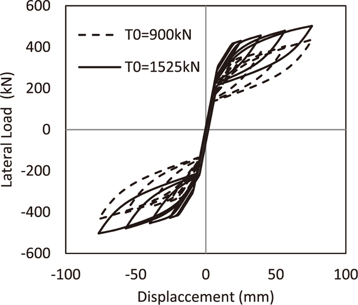
Lateral force-displacement (H-Δ) behavior of PT connections with different initial post tension force, is illustrated in Fig. 12. Firstly, T-stubs were not modelled in the post tensioned column bases. The initial PT force for S1, S6, S7, S8 and S9 after application of the axial force of the column was 614, 915, 1220, 1525 and 1830 kN, respectively. The applied axial force of the column was same for the models (587 kN). The result shows, different in the initial posttensioning force does not affect the elastic and plastic stiffness of the connections. Secondly, the column base was modelled completely (with T-stubs). The results show in Figs. 13 and 14. Energy that dissipated during the analysis was calculated by summing the area enclosed by the lateral load vs. displacement curve (see Fig. 13). The energy dissipation is associated with the performance of the T-stubs. The total energy dissipation is related to the size of the hysteretic loop. According to the Fig. 13, the cumulative energy dissipation at the ends of the analysis is the same for two specimens with the different initial PT force (15037 kN-mm).
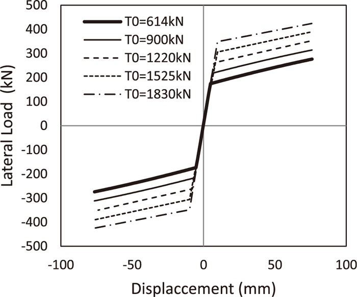
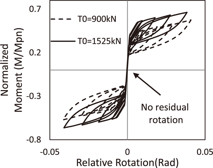
Figure 14 shows that the connection moment increases as the initial PT force increases. The decompression moments are 0.32Mp, and 0.46Mp for PT connections S6 and S8 respectively. Result shows that the maximum and decompression moment of the connection increase as the initial posttensioning force increases (Table 3).
According to the Fig. 14, when unloading, occurred the connection returns to its original position without residual rotation.
7.2. Effect of PT Bar Size
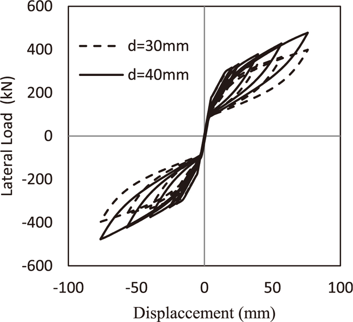
In order to investigate the effect of PT bar size on the connection behavior, comparison of the lateral load –displacement of the four models is shown in Fig. 15. The PT bar diameters were 30, 35, 40 and 45 mm for specimens S1, S2, S3 and S4 respectively. The models have the same initial post tensioning force (614 kN). As seen in Fig. 16, the plastic stiffness increases as the PT bar size increases (a tangent of line 3-4 in Fig. 4). The decompression moment is 0.23Mp for all PT connections. Lateral load-displacement and normalized moment-relative rotation plots for specimens S1 and S3 are presented in Figs. 16 and 17 respectively. The results show that initial stiffness for the two specimens is the same, but the plastic stiffness is different. Also the size of the hysteretic loop for two specimens is the same (13669 kN-mm), as shown as Fig. 16.
It is seen in Fig. 17 that the PT column base connection shows self-centering behavior with no residual rotation.
7.3. Effect of T-stubs Size
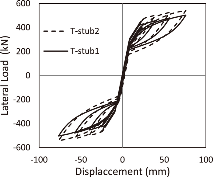
In order to investigate the effect of the T-stubs size on the energy dissipation, the lateral load-displacement of two specimen (S8 and S10) are compared in Fig. 18. The specimen (S8) and (S10) have the T-stub type (1) and (2) respectively. The initial post tensioning force and decompression moment is 1525 kN and 485.7 kN-m for two models. Results show, the initial stiffness of two models is the same. The initial stiffness of the connection was obtained from the lateral load versus lateral displacement response. Based on Fig. 18, hysteretic loop for S10 (T-stub 2) is larger than S8 (T-stub 1).
8. Comparison and Conclusion
This new connection has a few advantages over the existing and conventional connections such as that proposed by Chi.10) In our proposed connection, T-stubs are used for energy dissipation instead of the BRS plate. The T-stub is conventional device than BRS plate in connections. In the Chi’s column base, the BRS plate and keeper plate are welded by complete joint penetration (CJP) welding but T-stubs are bolted to the beam and column, therefore the potential risk of unexpected brittle failure at welded joint is reduced. Also cover plates that are used to prevent buckling of the BRS plates is eliminated in this connection. It was observed in Chi’s experimental that the BRS plates buckled about both the strong and weak axis but this problem is resolved in this connection by replacing the BRS with T-stubs.
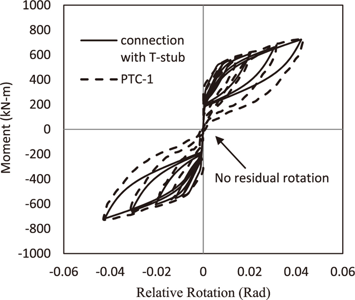
The comparison of the self-centering behavior of the new column base and Chi’s column base (PTC-1 and PTC-1D) is presented in this section. Moment-relative rotation plots for specimens PTC-110) and column base with T-stub is shown in Fig. 19. Also the comparison of the PTC-1D10) and proposed connection is presented in Fig. 20. The size of the beam and column, initial axial force in column and Initial post tensioning force are presented in Table 1. In the specimen PTC-1 and PTC-1D, the BRS plate buckled due to the gap between the BRS plate and cover plate.10) However, the buckling of the BRS plate did not affect the global behavior of the PT column base but the BRS need to be removed.10) It is also seen that yielding occurred along the entire length of the BRS plate.10) The failure mode of T-stubs in proposed connection is bolt failure. The designer could design the new connection so that only mode 1 dominated and bolt failure does not occur. In two cases (Chi’s and proposed connection), it is seen that the PT column base connection shows self-centering behavior with no residual rotation (Figs. 19 and 20). The size of the hysteretic loop for PTC-1 and PTC-1D is the larger than bolted T-stub connection. So that the energy dissipation of BRS plate is larger than T-stubs connection but the failure mode of BRS is removed in the proposed connection.
9. Summary
In this paper, the numerical simulation of the new post-tensioned (PT) column base connection was evaluated using the OpenSees computer program. The proposed post tensioned column base consists of high strength posttensioned bars, reinforcing plate and bolted T-stubs. The PT bars provide restoring force for self-centering behavior while the T-stubs dissipate energy by yielding. The effects of the initial PT force, T-stubs size and PT bar size on the cyclic behavior of the PT column base connection were investigated.
The result indicates, proposed post-tensioned column base showed stable hysteretic behavior and there is no residual rotation at the posttensioned column base.
Parametric studies showed: 1) as the initial post tension force in the same column size increased, the connection moment increased. 2) Decompression moment also increased as the initial PT force of the column increased.
3) For the same initial post tensioning force, the plastic stiffness increases as the PT bar size increases, but the energy dissipation is constant. 4) Finally Connections with stronger and stiffer T-stub have greater energy dissipation.
References
- 1) J. Ricles, R. Sause, M. Garlock and C. Zhao: J. Struct. Eng. ASCE, 127 (2001), No. 2, 113.
- 2) J. Ricles, R. Sause, S. Peng and L. Lu: J. Struct. Eng. ASCE, 128 (2002), No. 7, 850.
- 3) M. Garlock, J. Ricles and R. Sause: J. Struct. Eng. ASCE, 131 (2005), No. 3, 438.
- 4) M. Garlock, R. Sause and J. Ricles: J. Struct. Eng. ASCE, 133 (2007), No. 3, 389.
- 5) C. Christopoulos, A. Filiatrault, C. M. Uang and B. Folz: J. Struct. Eng. ASCE, 128 (2002), No. 9, 1111.
- 6) B. Morgen and Y. Kurama: PCI J., 49 (2004), No. 4, 112.
- 7) P. Rojas, J. Ricles and R. Sause: J. Struct. Eng. ASCE, 131 (2005), No. 4, 529.
- 8) M. Wolski, J. Ricles and R. Sause: J. Struct. Eng. ASCE, 135 (2009), No. 5, 479.
- 9) K. Tsai, C. Chou, L. Lin, C. Chen and S. Jhang: Earthq. Eng. Struct. Dyn., 37 (2008), 627.
- 10) H. Chi and J. Liu: J. Constr Steel Res., 78 (2012), 117.
- 11) Eurocode 3, Design of Steel Structures. Part 1.8: Design of Joints. Stage 49 draft, European Committee for Standardization, Brussels, (2003).
- 12) F. McKenna. G. L. Fenves and M. H. Scott: Open System for Earthquake Engineering Simulation, University of California, Berkeley, CA, (2000), http://OpenSees.berkeley.edu. (accessed 2013-01-08)
- 13) AISC: Seismic Provisions for Structural Steel Buildings: ANSI/AISC 341-05, AISC, Chicago, Ill, (2005).