Review
The Solidification Behavior of Slags: Phenomena Related to Mold Slags
2014 Volume 54 Issue 12 Pages 2665-2671
Details
2014 Volume 54 Issue 12 Pages 2665-2671
The solidification behavior of slags is a complex subject due to the varied chemical compositions of steelmaking slags. However, recent experimental developments, using the fact that slags that do not contain significant quantities of transition metal oxides are transparent, has allowed the development of optical techniques to observe slag solidification behavior. While “curiosity based research” was the initiator of such studies, it has quickly become apparent that observation of the phenomenon of slag solidification has lead to a much deeper understanding of the role of slag solidification behavior in the process of the continuous casting of steel. In this paper findings from observation of slag solidification will be discussed with reference to developments in continuous casting.
In the steelmaking process, slags react with liquid steel to either refine or contaminate depending upon local chemical conditions. Slags also absorb second phase particles such as alumina, cover liquid steel to prevent re-oxidation, wet liquid steel and act as a lubricant or a heat transfer promoter or reducer depending upon local thermal conditions. Slags generally are used in extreme thermal gradients in continuous casting and the solidification behavior of a slag is of extreme interest in the mold of a continuous caster.
Slags are also part of the family of oxides that can form glasses during cooling, rather than precipitate the most thermodynamically stable phase and, as such, can have a variety of solidification morphologies depending on their thermal history. They can be glasses, partially crystalline – a mixture of a solid and a glass, or fully crystalline. Their morphology can also vary with time depending upon thermal history. For example, reheating after cooling will almost always increase the crystalline volume fraction of solidified slags.
When glasses, slags are generally colorless when iron and manganese oxide contents are low but can darken significantly with the addition of FeO and MnO. Thus, their overall heat transfer characteristics are a function of their chemistry and their crystallized volume fraction as radiation heat transfer rates are important at the shell temperatures that occur in the mold of a continuous casting machine where heat transfer characteristics vary markedly with mold design, flux design and time of casting, as the slag solidification structure can age.
In slags mass transfer is the predominant mechanism which controls the solidification rate (unlike metal solidification) and rapid cooling quickly leads to a low volume of crystallite or glass formation. Slags can also be chemically unstable, especially those containing fluorine and sodium oxide and certain slags vary in chemistry with holding time due to evaporation. Slags can also dissolve gasses of which water vapor is perhaps the most important and the presence of dissolved water in slags markedly changes their solidification behavior and can lead to the formation of bubbles within the slags during cooling.
In this paper I will discuss the solidification behavior of slags and highlight the work that resulted in my collaboration with a number of Professors, post doctoral and graduate students during my career. In particular, I will discuss the effect of mold slag solidification phenomenon on the operation of a continuous casting mold.
When I began my academic career in 1986 I was fortunate to immediately begin a long-term collaboration with Prof. Itaru Jimbo. Without this collaboration, I would not have been successful in my academic career.1,2,3,4,5,6,7,8,9,10,11,12,13,14,15,16,17,18) Our work together was focused on interfacial energies between slags and steels and began my interest in interfacial considerations during the continuous casting of steel. My first presentation in Japan occurred in 19903) and was a joint publication with Prof. Jimbo. My first publication in ISIJ5) occurred in 1992 and was also co-authored with Prof. Jimbo.
I first visited Japan in 1983 as part of a delegation interested in the state of the art of the continuous casting of steel. My memories of vising Nippon Steel, Kawasaki Steel, Sumitomo Metal and Kobe Steel are still very fresh as Japanese technology in this area significantly had surpassed anything in the United States at that time. In 1990 I made my fourth visit to Japan but this time as a young professor accompanying Prof. Richard Fruehan who had been tasked by the National Science Foundation (NSF) to study fundamental and long-term research in both universities and industry as it related to steel processing.19,20) During this visit I met Prof. Fuwa, Prof. Sano, Prof Ban-ya and Prof. Morita, the great metallurgical professors of that time and would know all four well for the next twenty years. At that time I also met again Professors Hino and Sasaki, both who had been postdoctoral fellows at the University of Pennsylvania where Prof Sasaki was in the same lab as I (under Professor Belton), while Prof Hino was working with Professor Gaskell. I also met Professor Iguchi, Professor Iwase and Professor Suzuki. In industry I met Prof. Emi, also a Penn alumni (with Prof. Bockris). I visited Tokyo, Kyoto, Osaka and Sendai and met the leaders of the thermodynamics and kinetics of steelmaking community in Japan. I, with Prof. Iguchi, subsequently organized a US-Japan symposium in Tokyo.
Starting in 1987 I developed a close relationship with Professors from Japan that has continued to this day. I have been fortunate to do research with Prof. Nagasaka (Tohoku),21,22,23) Professor Suzuki (Tokyo),24,25,26,27,28) Prof Kashiwaya (Hokkaido),29,30,31,32,33,34,35,36,37,38,39) Professor Ueda (Tohoku)40,41,42,43) and Professor Shibata (Tohoku).44,45,46,47) In addition, I had four excellent graduate students from Japan: Dr. K. Shimizu,48,49,50) Dr. H. Todoroki,24,25,26,27) M. Nakata51,52,53) and K. Fuchigami.46) My Japanese connection has lead to over 50 publications in a span of 18 years.
2.1. SlagsTo the chemical metallurgist slags were very important as the medium that allowed the removal of oxides, sulfur and phosphorus from liquid iron and liquid steel. Understanding slag chemistry and its manipulation brought about the era of “Clean Steel” ladle technology. Of course, Professors Fuwa, Ban-ya and Sano, all who studied at MIT with Professors Chipman and Elliott, made great contributions in our understanding of the thermodynamics of slags and slag-steel interactions. The kinetics of slag metal reactions would be clarified by Prof. Fruehan’s group and our understanding of refining would be led by the pioneering work of Prof. Szekely and his group in understanding the importance of fluid flow in liquid steel processing.
One area that was not well understood or studied was that of slag solidification phenomena as, until the advent of continuous casting, there was no apparent need for such an understanding. While ladle slags were designed to be liquid at steelmaking temperatures, to be able to react with sulfur and to absorb solid oxides, mold slags had significantly greater requirements due to the extreme thermal gradients in the mold of a continuous caster.
2.2. Observation of the Solidification Behavior of Mold SlagsLiquid slags that are used during the continuous casting of steel must be stable and liquid at steelmaking temperatures, wet both liquid and solid steels, adsorb solid oxides, remain liquid and fluid in extreme conditions of thermal gradient and solidify (or crystallize) under defined conditions. The liquid flux layer that infiltrates between the cast strand and the mold wall can be less than 1 mm in thickness with a temperature differential that varies from 1530°C to 200°C depending on position between the solidifying shell and the water cooled copper molds used during the continuous casting of steel.
Liquid slags in ladle metallurgy are based on the CaO–Al2O3 system and usually contain some MgO to reduce ladle lining wear rate. FeO, MnO and SiO2 can also be present and amounts that are determined by one’s ability to control furnace slag carry over. In electric furnace steelmaking it is common to find FeO + MnO levels below 1%, while in BOF operations higher FeO+MnO levels are common (3 to 5%). In operations with limited slag control, slag killing with aluminum or calcium carbide is common as a means to reduce FeO+MnO levels. Additions of Calcium Fluoride can aid in liquid slag formation; however, it is unusual for such additions to result in significant fluoride content in the ladle slags due to evaporation of CaF2 and SiF4.
Mold slags are chemically different from ladle slags as their operating temperatures are much lower than that found in ladles. First all of liquid formation at low temperatures is desired, thus the starting point of mold fluxes is the CaO–SiO2 system. Additions of the glass formers Na2O, K20, Li2O and B2O3 are also common. In addition significant quantities of CaF2 can also be found. FeO, MnO, Al2O3, ZrO2, and MgO can also be added or adsorbed from the steel or the submerged entry nozzle. As such mold slags are not chemically stable in contact with killed liquid steels and the actual flux chemistry in contact with liquid steel is dependent on both the initial powder chemistry and its interaction with the liquid steel. In addition, above 900°C, NaF vapor is stable and fumes off the top of the mold slag if surface temperature rise above 900°C.
Slags are ionic liquids, can conduct electricity and are generally easy glass formers. Slags can also interact with water vapor and, even, at high temperatures, have water solubility that can lead to bubble formation or even outgassing during crystallization.
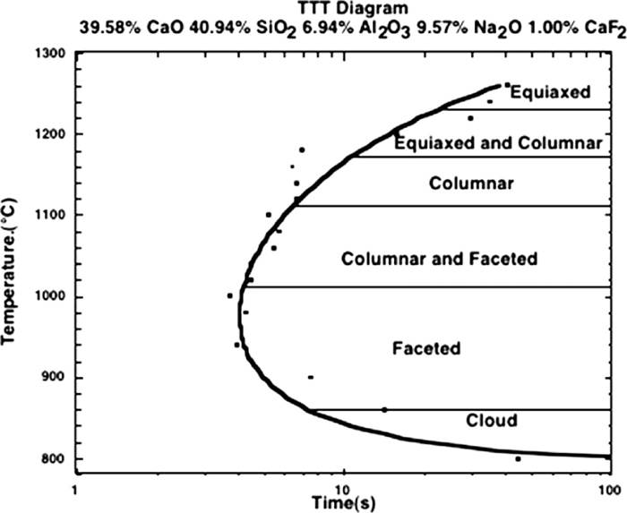
To understand the solidification behavior of slags one must accept that they are glass formers and, as such, can be significantly undercooled with respect to their thermodynamically predicted transformation temperature. A range of solidification morphologies is possible and actual structures depend upon cooling rate and thermal history. Thus one can find glass formation, a mixture of glass and crystallized solid or a fully solidified structure that exhibits segregation. During dynamic cooling, as nucleation behavior determines the first phase to form, not the phase diagram, metastable phases can be found. Time-Temperature-Transformation (TTT) diagrams are useful in understanding solidification behavior and an example by Kashiwaya33) is given in Fig. 1.

TTT diagram for an industrial mold slag.33)
In this diagram one can observe that (1) at high cooling rates a glass can be formed; (2) depending on the cooling path the phase that nucleates and grows is different – dicalcium silicate at high temperatures and cuspidine at lower temperatures and (3) that it is possible to significantly undercool this slag before the initiation of solidification.
The effect of chemistry change can also be easily measured using TTT diagrams as shown in Fig. 2 where the effect of sodium oxide content on the solidification behavior of a slag is documented.

The effect of sodium oxide on the TTT curve of a calcium silicate based slag.35)
These TTT diagrams can be measured using either a single (SHTT) or a Double Hot thermocouple technique (DHTT).33,34,51,52,53) Of course, actual operations occur not in isothermal slices but in a continuously cooling environment that leads to the necessity of developing CCT diagrams based upon actual mold operations where the hot face next to the shell and the cold face next to the mold wall are simulated. An example of the difference between a CCT and a TT curve is given in Fig. 3 where the onset of solidification is indicated by the solid dots on the CCT cooling rate curves. During continuous cooling the time to onset of solidification can be significantly increased when compared to isothermal cooling.

Comparison of a TTT and a CCT curve for a slag.57)
A simulation of mold solidification is shown in Fig. 4 using the DHTT where one thermocouple follows the cooling curve of the mold wall and the other the cooling curve of the solidified steel shell. To the right of the photograph is the cold face and to the left the hot face. In this photograph, taken after approximately one minute after initiation of the experiment, a glassy area can be seen against the cold face (approximately 300°C), liquid slag is against the hot face (approximately 1100°C) and between these two limits is a crystallized mass that grows with time. At time zero the liquid slag and all chemistries in the liquid are equivalent. Immediately on cooling of the cold face thermocouple a glass forms against the cold thermocouple and the extent of this glass phase increases with time. Crystallization occurs by nucleation of Cuspidine in the liquid and the first crystals form ahead of the glass phase, the remaining liquid on the hot side of the experiment then changes composition due to segregation. With time the extent of the crystallized area increases towards the hot thermocouple. Thus, as the liquid mold slag is sheared and moves down the mold its chemistry changes and it can either remain liquid longer than expected from the phase diagram or solidify at a higher temperature, depending on chemistry changes in this liquid. The lubrication behavior depends upon the details of solidification behavior of the slag and the fluid flow conditions between the shell and the mold.

Photograph of a simulated solidification of a mold slag using a DHTT apparatus where the hot face is cooling as if it were the shell of continuous caster and the cold face is at the temperature of a water cooled mold.33) Thermal fields are courtesy of calculations by Professor Brian Thomas.64)
Initially there is a significant portion of heat transferred by radiation across the liquid film; however, once crystallization occurs radiation is blocked and the total heat transfer rate decreases. If one envisions a small volume of mold slag that is moving down the mold as the strand is removed then one can understand that the glass area sticks to the mold surface and remains in contact with mold unless physically removed. The liquid film will slowly transform over time as crystallization occurs with the crystallized fraction growing more slowly as one moves down the mold as crystal growth rate is dependent on diffusion rates in the liquid mold slag. The slag continues to evolve with time and heat transfer rates in molds can be seen to decrease as a function of time to the point that casting speeds must be reduced. The solution to this problem is to pause casting speed, allow the shell to bulge against the mold, cool, strengthen and then on increasing casting the glass film is removed and a new film is deposited on the mold wall. Heat transfer rates then increase to their initial state.
Often in continuous casting it is assumed that a gap occurs between the mold wall and the slag film and often a gap interface resistance to heat transfer is ascribed to allow mathematical models to be tuned to actual data from molds in continuous casting machines. One should be careful when one uses a mathematical process (the adding of an additional tunable parameter) to a complex process in describing that parameter in physical terms. For example, in ingot, billet or strip casting, where there is intermittent contact between the shell and the mold, it is clear that there must be a parameter to account for the fact that one does not have perfect contact and a gap interface resistance parameter has some relationship to the physical reality, even though this cannot be calculated from first principles and is a tuning parameter of the model. In the mold of a continuous caster there is no physical unfilled gap between the shell and the mold, but intermittent contact between the shell and the mold where all other spaces are filled with a liquid mold slag. In the best of possibilities, at the top of the mold there is no physical contact when the mold is oscillating and a liquid flux is being fed into the pace between the shell and the mold. In Fig. 5, the flux layer from a mold simulator is seen to wet and stick to the mold wall and become a replica of the solidifying shell where the flux layer thickness varies with the variation in the shell profile, being deeper in the oscillation marks and shallower elsewhere.54,55)

A continuous casting simulation where the shell is removed from the mold. On the left (a) is a water cooled mold with the slag layer attached. On the right (b) is the solidified shell. Photographs by Badri.55)
As the slag moves down the mold it cools and flows over previously cooled slag and the thermal gradients within the slag film are a function of position and time. Crystallization of the slag reduces the radiative heat transfer rate as shown by Wang.56) As the crystallization phenomena causes significant stresses, the slag film may crack or buckle leading to a changing interface contact especially in the lower parts of the mold. The radiative heat transfer rates can decrease by up to 20% and the contact conditions lower in the mold can change and affect conduction heat transfer rates. Therefore, the heat transfer in the mold is intimately affected by the nature of solidification and its effects on transport mechanisms.
The double hot thermocouple technique as developed by Kashiwaya et al. at CMU30,31,32,33,34,35) has become an excellent tool for understanding the solidification structure of slags. The extreme sensitivity of solidification structure to both cooling rate and final temperature can be easily photographed in slags that are transparent. For example, a morphological TTT diagram was developed by Orrling57) is shown in Fig. 6 and indicates that solidification structure is extremely sensitive to the exact solidification thermal conditions. Photographs of the various structures are given in Fig. 7. It is surprising that slag solidification is very similar in morphology to that of water solidification where crystal snowflakes are easily identifiable within these structures.
TTT diagram showing type of solidification morphology depending on isothermal temperature observed by Orrling.57)
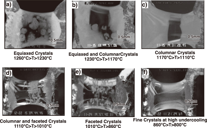
Variations of crystal morphology with temperature. Photographs by Orrling.57)
A surprising development from the DHTT studies was the realization that humidity affects the solidification behavior of slags, changes the TTT diagram (making solidification occur earlier) (Fig. 8) and increases the observed nucleation frequency and growth rate58,59) of any precipitated crystals. Also in the presence of water vapor, bubble formation can occur during solidification where water vapor bubbles nucleate and grow ahead of growing crystals. This is again similar to ice formation where dissolved oxygen precipitates as bubbles ahead of growing ice crystals giving rise to bubbles in ice.
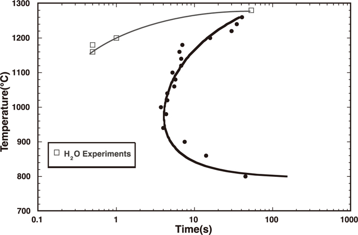
Effect of water vapor on the TTT curve.57)
One major issue in relation to the DHTT technique is the care one must take when attempting to make measurements using slags that contain significant quantities of fluorine due to the highly volatile nature of NaF and SiF4. This means that the measurements are function of time due to changing chemistry as in the DHTT slag sample size is small and its surface area is large. Only one measurement is possible on any slag sample and experimental time must be short and chemistry must be determined after the experiment to endure the chemical changes are small. Another issue in using mold slags in the DHTT is that slags containing significant quantities of FeO, MnO and TiO2 are not fully transparent and difficult to observe. DHTT experiments work best with stable oxides.
In liquid metals that are cooling, the transfer of heat controls the solidification rate and normal solidification, where the temperature gradient is positive across the interface and heat transfer is through the growing shell, is the predominant mechanism for solidification until one reaches the point where equiaxed formation can occur – when liquid is undercooled.
In slags the solidification behavior is controlled primarily by diffusion in the liquid rather than heat transfer and all solidification occurs predominantly in an undercooled melt. Glass formation is possible when cooling rates are high. Thus equiaxed crystal growth is quite common in slags unless one nucleates from a surface (such as the thermocouple in a DHTT experiment.
The solidification behavior of slags is quite different than most metals as crystal growth rates decrease with temperature. For example in Fig. 9, which chronicles the undercooled solidification rate for liquid iron, the growth rate increases with undercooling46) where growth rates are significant and measured in mm per second. In Fig. 10, the growth rates in calcium aluminate are shown where growth decreases with undercooling and rates are small - measured in micrometers per second.
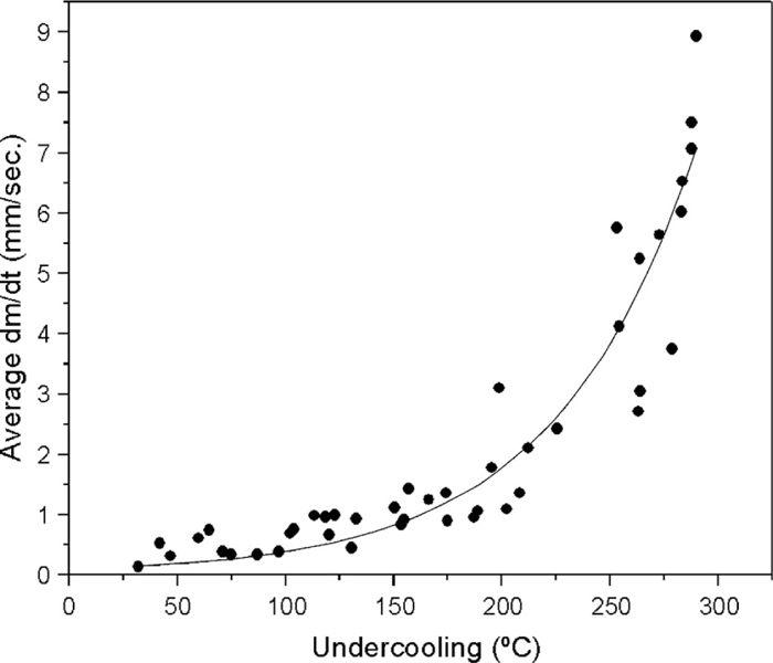
Undercooled growth rate in liquid iron.46)
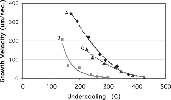
The growth rate of precipitated crystals in three different calcium aluminate slags as a function of undercooling.59)
Orrling showed that the growth rates of equiaxed crystals in slags fits the diffusion theory growth rate as outlined by Ivantsov by using confocal microscopy.60) As growth rate and dissolution rate are similar phenomenon, diffusion rates in these liquids have been estimated using such techniques as measuring dissolution rates of particles in liquid slags at constant temperature. It should be noted that growth can also be used in isothermal experiments for a similar purpose61,62,63) and Sridhar Seetharaman63) developed the following diagram (Fig. 11) to choose slag chemistries for high dissolution rates of alumina in a CaO–Al2O3–SiO2 slag as indicated by the concentration difference and the inverse of viscosity (ΔC/μ), where the flux J units are gm/cm2 sec and the equation can be written as:
| (1) |
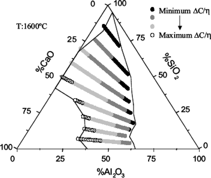
Areas of highest potential dissolution rate based upon the ratio of driving force for dissolution reported by Sridhar.63)
In mold slags the solubility of alumina and zirconia (ΔC) can be significant and the viscosity of mold fluxes (μ) can be quite low (thus diffusion rates can be high). This can lead to severe erosion of Submerged Entry Nozzles (SEN) in the mold of a continuous casting machine as ΔC/μ is a maximized. Liquid steel dissolves graphite in the SEN and spreads (wetting) removing graphite. The liquid steel then contacts the ceramic and retracts (de-wetting) leading to a cyclic flow of slag and steel at the slag/steel interface. Thus the potential for extreme levels of erosion are high as there is a large capacity for dissolution in the slags, high diffusion rates and a continual mechanism to bring fresh ceramic to the slag. Of course this leads to local chemical inhomogeneity in the mold slag that can affect its solidification behavior and induce cracks in continuously cast product.
4.1. Potential Future ConsiderationsThe mold in a continuous caster is the key to understanding the surface created during casting. Significant modeling work has been focused on our understanding the initiation of steel solidification and the subsequent growth of the solidified shell. Unless the solidification processes in a liquid slag are fully understood, it will be impossible to develop an appropriate model of the mold of a continuous caster that enables mold design, nozzle design, slag chemistry and mold operational parameters such as oscillation pattern, frequency, stroke and casting speed to be coupled for a given steel grade. Initial work on this subject was documented in the thesis of Moinet.65)
Future work in this area should be focused on the measurement and prediction of both TTT and CCT diagrams as a function of slag chemistry. In addition, development of appropriate heat transfer models to accurately predict the thermal profile within the slag film as a function of position and time in the mold are necessary in order to fully understand the temporal nature of the transformations that occur within a liquid slag. Of course, the effect of atmosphere, especially humidity, must be documented to enable accurate prediction of solidification structure and porosity due to gas release at the growing solidification front to be properly documented.
The future for mold powders and the subsequent slags that develop upon melting must be towards chemistries that are stable in contact with liquid steels. Thus future developments will lead to mold fluxes that are: (1) without fluorine to eliminate fluoride off gassing and acidification of the secondary cooling water system; (2) without solid carbon additions to eliminate CO off gassing and the potential for steel surface recarburization; (3) stable with regard to the ceramic nozzle or at least with a minimal nozzle erosion rate; (4) without easily reducible oxides such as Na2O, FeO and MnO; and, (5) difficult to emulsify (high viscosity and interfacial tension). The development of mold slags that fit these requirements and can control heat transfer rates in the mold within specified limits will be a significant future challenge.
The solidification of slags is a fascinating area from both a fundamental and practical point of view. In the continuous casting of steels it is imperative that one fully understand this complex behavior in order to understand the complexities of heat transfer and lubrication within the mold.
Without my ongoing relationship with my collaborators from Japan, my career could not have been successful. I would like to thank all of my friends in Japan for their support over the years. This research was carried out at the Center for Iron and Steelmaking Research at Carnegie Mellon University and I would like to thank Richard Fruehan and the member companies of the CISR for their support of my research in this area. Some of the topics in this paper were also discussed in the Fruehan Symposium Proceedings,58) a publication to honor Richard Fruehan in 2011.