Abstract
This article describes application of computational simulation for manufacturing of castings using investment casting technique. A mathematical model was created describing the process of melted metal pouring into the ceramic shell with its further solidification. Using this model the process of manufacturing single-crystal patterns from heat-resistant nickel superalloy was simulated. The obtained computational model was verified by the temperature measuring of the real-life production experiment. Using mathematical simulation the speed of the patterns moving out was optimized to increase temperature gradient on the casting.
1. Introduction
One of the techniques used for manufacturing high-quality machines components is investment casting which allows in one operation to manufacture complex geometry castings (including thin-walls blades) for expensive heat-resistant alloys which are not very machinable.1) But due to the production process complexity and large number of factors influencing on the resulted product quality solidification should be checked especially strictly. Mathematical simulation of processes associated with components manufacture by investment castings allows to reduce costs because gating system design and temperature-time parameters of the technological process are exercised in mathematical model virtual space instead of real-life expensive casts. Low cost and short time of computational experiment execution as well as large volume and visualization of the obtained information about the technological process progress and quality of the future casting make computational simulation an important research tool.2)
This topic is novelty and scantily investigated. Earlier, this problem was considered in.3) This work studies the process of manufacturing single-crystal patterns from heat-resistant nickel alloys. A mathematical model is built which describes this process. The model is verified by comparing the data obtained by computational experiment with temperature measuring results. Mathematical model application is examined in terms of optimizing the speed of the casting moving out of shells preheating furnace.
2. Mathematical Model Building
Let us study the process of manufacturing single-crystal patterns from heat-resistant nickel alloys. The partners are casted in a special-purpose machine of direct solidification. Solidification is proceeding simultaneously in two shells obtained by investment casting and poured with ceramics as per Shaw technique.4) Each shell consists of three patterns.
Before the pouring the melted material the shells are heated in a furnace during 4200 seconds up to process-oriented temperature. Then the melted nickel alloy is poured in. From the moment of pouring up to shells moving out the patterns are conditioned within ten minutes. Inside the machine during the whole process the temperature is maintained at the level higher than the alloy liquidus point. Solidification and single-crystal structure perfection are defined by the speed of shells moving out of the heating module. Now we will describe the mathematical process. Figure 1 shows the circuit of the casting manufacturing including the ceramic shell, Shaw ceramics and the region of the casting formation.
Non-stationary thermal profiles in computational area while pouring metal and solidification is studied using differential equation of heat conductivity.
|
ρ
1
∂H
∂T
∂T
∂t
+
ρ
1
U
¯
⋅gradT=∇(
λ
1
∇T)
x
¯
∈
V
1
,
|
where the casting material enthalpy
|
H
1
(T)=
∫
0
T
c
p
1
(T)dT+L[
1–
g
s
(T)
]
,
|
for the shell material and Shaw ceramics the heat conductivity differential equation looks as follows:
|
ρ
i
∂
H
i
∂T
∂T
∂t
=∇(
λ
i
∇T)
x
¯
∈
V
i
.
|
|
H
i
(T)=
∫
0
T
c
pi
(T)dT
,
|
where indices: 1, 2 and 3 refer to areas
V1,
V2 and
V3 respectively,
T – temperature;
t – time;
ρ – material density;
сp – specific heat capacity;
L – specific heat of phase transition;
λ =
λ (
T) – heat conductivity factor;
U
¯
=(
u
1
,
u
2
,
u
3
)
– effective melting rate vector calculated through liquid phase actual speed
U
¯
1
as follows:
U
¯
=
g
l
⋅
U
¯
1
;
gl – liquid phase portion;
gs – solid phase portion
gs = 1 –
gl;
x
¯
=(
x
1
,x
,
2
x
3
)
– radius-vector in Cartesian coordinate system.
Heat conductivity equation additionally is completed with boundary conditions on the surface of the shell-casting contact:
|
–
λ
3
∂T
∂n
=–
λ
1
∂T
∂n
=
α
13
(
T
1
–
T
3
)
x
¯
∈
S
2
.
|
On the boundaries of heat conductivity with environment the conditions are as follows:
|
λ
i
∂T
∂n
=–
α
ic
(
T
i
–
T
c
)–εσ(
T
i
4
–
T
c
4
)
,
|
|
i={
1
,
x
¯
∈
S
4
2,
x
¯
∈
S
5
3,
x
¯
∈
S
6
,
|
where
α (
t) – heat release coefficient determined as per,
3) index
с is for environment parameters,
ε emissivity factor,
σ – Stefan – Boltzmann constant.
Heat transfer conditions between the Shaw ceramics and the shell are considered to be ideal. T2 = T3
x
¯
∈
S
3
.
Initial conditions are transferred to the pored metal temperature and the shell with Shaw ceramics
T
i
(
x
¯
,0)=
T
0i
(
x
¯
), i=1,2,3;
x
¯
∈
V
i
.
To model the process of melted metal pouring into the ceramic shell and to calculate heat and mass transfer the motion differential equation is applied. In computational area we consider non-isothermal laminar flow of non-compressed Newtonian viscous liquid. Phase interface is not clearly distinguished.
|
ρ
1
∂
U
¯
∂τ
+
ρ
1
2
grad(
U
¯
2
)+2
ρ
1
(
rot
U
¯
×
U
¯
)
=–
ρ
1
g+grad(p)+grad[
μdiv(
U
¯
)
+
μ
K
U
¯
]
,
|
– gravitational acceleration;
p – pressure;
μ– viscosity ratio;
K – dendrite frame structure permeability calculated as per Karman-Kozeny equation:
K=
g
l
3
k
S
V
2
, where
S
V
=
6(
1–
g
l
)
D
– specific surface of solid-liquid phase,
D – dendrite typical size,
k – Karman constant value,
k = 5.
The motion equation is additionally completed with the evolutionary equation of compressible medium continuity in liquid phase area to meet the mass conservation law:
|
∂
ρ
0
∂t
+div(
ρ
0
U
¯
)
=0,
x
¯
∈
V
1
.
|
The motion equation is additionally completed with the following boundary conditions:
σ
ˆ
⋅
n
¯
=
p
¯
at
x
¯
∈
S
4
– the condition of tangent lines absence (
p
¯
τ
=0
) and simple stress equity with gas pressure at free surface (
p
¯
n
=–
p
c
n
¯
), n – unit normal element at the casting free surface.
Free surface geometry S4 is defined as related to time through relationship of simple stress and metal surface tension
x
¯
∈
S
4
, according to the procedure described in.5)
At the boundary S2 for the solidified metal the speed
U
¯
is automatically becoming 0 because
U
¯
=
g
l
⋅
U
¯
1
, and gl = 0.
It is assumed that at initial point at surface
x
¯
∈
S
1
there is a melted metal source with the known initial speed distribution:
U
¯
0
=(
0,0,
u
0
)
.
3. Mathematical Model Verification
Considering the abovementioned mathematical relations the finite-element model of single-crystal patterns manufacture was built. Solution area included casting body, shell and Shaw ceramics.4) Cooling conditions were specified using special boundary conditions (Fig. 2).
To simulate the process of pouring and solidification of the air cleaner case we used the multi-purpose software solution and in particular ProCAST system of casting process computer simulation (Fig. 3).
To verify the proposed mathematical model an experiment was conducted at Aviadvigatel’s development plant for manufacturing single-crystal patterns from nickel superalloy. During the work a special-purpose vacuum furnace was used for the preheating of the shells. Two modules were poured in the preliminary heated shells. After certain time the patterns were slowly moved out of the furnace to achieve flat thermal gradient opposite to crystals growth direction.
At carrying out full-scale experiment the ceramic shell and the casting cavity were fitted with special-purpose thermal sensors with numbers 7…12 (thermocouples arrangement is given in Fig. 4). Thermocouples with odd numbers showed the temperature in the ceramic shell and the thermocouples with even numbers – in the casting.
The obtained thermocouples readings were interpolated into the temperature-time relationship curves. These curves were compared with computational calculation results in points corresponding to sensors arrangement. Figure 5 show comparison of computational calculations with the thermocouples data in the shell and in the casting correspondingly.
Absolute accuracy for mathematical model didn’t exceed 10°С that is less than 1% in solidification temperature intervals. Therefore correspondence between numerical simulation results and experimental data was proved. It confirms the possibility of numerical models wide application in production process.
4. Optimization of the Patterns Moving Out Speed
Having proved that numerical model truly reflects thermal processes in a casting assembly let us modify the production process to improve the patterns structure.
One of the quality parameters is the thermal gradient width which is influence by the shell moving out speed. Therefore we will optimize the speed of the shell moving out of the furnace to achieve maximum temperature gradient. As an optimized function let us chose the width of solidification front-line and let it tend to a minimum. For optimization we use gradient descend method with a constant step.
where
ω
¯
=(
0,0,
ω
z
)
– the speed of the patterns moving out, and
D – the width of solidification front-line tending to a minimum
|
–∇D=
D
1
–
D
2
ω
¯
2
–
ω
¯
1
|
Where λ = 0.5 – the selected step for the gradient descend method.
|
ω
¯
[k+1]
=
ω
¯
[k]
–λ∇D(
ω
¯
[k]
)
|
Criteria for breaking the process of minimum definition:
|
‖
ω
¯
[k+1]
–
ω
¯
[k]
‖≤ε, where ε=
10
–3
|
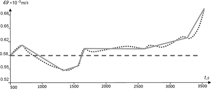
As a result for speed a temporary relationship was obtained (Fig. 4). For convenient application of the optimized speed function in the production process it was approximated by the straight line (Fig. 6).
It can be emphasized that on pattern castings the solid-liquid area width reduced sufficiently after optimization. Therefore the change of the patterns moving out speed led to the gradient increase in the castings.
Table 1 specifies thermal gradient along the casting length before and after optimization of the moving out speed.
Table 1. Thermal gradient in the casting.
| Casting part | At the beginning of the starting cone | At the end of the starting cone | At the beginning of the casting body | In the middle of the casting body | At the end of the casting body |
|---|
| Before optimization | 3.4 × 10⁻³ K/m | 2.3 × 10⁻³ K/m | 1.5 × 10⁻³ K/m | 1.3 × 10⁻³ K/m | 1.4 × 10⁻³ K/m |
| After optimization | 5.0 × 10⁻³ K/m | 4.2 × 10⁻³ K/m | 3.7 × 10⁻³ K/m | 3.4 × 10⁻³ K/m | 4.7 × 10⁻³ K/m |
5. Conclusions
Hence computational analysis application allows not only to study single-crystal structure formation from inside but also provides a possibility of carrying out numerical experiments for investigating process and design parameters influence on manufacturing single-crystal castings of gas turbine engine parts which is problematic and unreasonably expensive if it is done at real-life patterns. It allows to increase the quality of manufactured castings sufficiently and to minimize the risk of possible defects occurrence.
References
- 1) J. A. Dantzig and M. Rappaz: Solidification, EPFL Press, Lausanne, (2009), 9.
- 2) A. B. A. V. Monastyrsky, V. P. Monastyrsky and E. M. Levitan: Casting Process Development for Industrial Gas Turbine Large Blades Using Polygon and ProCAST Systems, Casting Production, No. 9 (2007), 29.
- 3) A. A. S. Dubrovskaya and K. A. Dongauze: Numerical Study of Process and Design Parameters Influence on Manufacturing Single-Crystal Castings of Gas Turbine Engine Parts, PSTU Newsletter Applied Mathematics and Mechanics, No. 9, Publishing office of Perm State Polytechnic University, Perm, Russia, (2011), 102.
- 4) E. P. Degarmo, J. T. Black and R. A. Kohser: A. Materials and Processes in Manufacturing, 9th ed., Wiley, New York, (2003), 315.
- 5) J. U. Brackbill, D. B. Kothe and C. Zemach: J. Comput. Phys., 100 (1992), 335.