Abstract
Recent developments of an advanced numerical model for Continuous Casting of steel unveiled at the previous 2010 CSSCR Conference in Sapporo, Japan are presented. These include coupling of the existing multiphase, heat transfer and solidification model to argon injection for tracking bubble trajectories in the SEN, metal bulk and across the slag bed after passing through the metal surface. Hence, description of a method for adding gas injection in combination with a multiphase model for tracking metal/slag interfaces (Discrete Phase Model + Volume Of Fluid, DPM+VOF) is given.
Validation is supported by tests on a revamped Continuous Casting Simulator (CCS-1) based on a low melting point alloy, which can realistically replicate the flow conditions in the caster. Metal-slag-argon flow predictions were compared to observations in the physical model showing good agreement on features such as discharging jets, rolls, standing waves and argon distribution measured through a variety of techniques such as ultrasound, electromagnetic probes and video sequences.
Ultimately, the model makes possible the prediction of stable or unstable flows within the mould as a function of different argon flow-rates and bubble sizes. Application to industrial practice is an ongoing task and preliminary results are illustrated. The robustness of the model combined with direct observations in CCS-1 make possible the description of phenomena difficult to observe in the caster (e.g. argon injection and metal flow), but critical for the stability of the process and the quality of cast products.
1. Introduction
An appropriate control of the metal flow in the Submerged Entry Nozzle (SEN) and mould during Continuous Casting (CC) is critical to ensure the quality of products and safe operation of the caster. However, controlling the liquid steel inside the mould is not a trivial task and unstable flow problems plague the operation of modern casters.1,2,3,4) Unsteady flows often lead to poor level control and uneven solidification within the mould; which have been linked to the formation of defects such as deep oscillation marks, cracks, depressions, etc.5,6,7) These defects are strongly linked to the mechanisms of initial shell solidification and growth in the mould. However, solidification itself is a complex combination of physical phenomena which include heat transfer, phase transformations and solid mechanics interacting simultaneously with the metal flow to form the solid shell within a time lapse of few seconds.
Numerical modelling is a feasible alternative to describe these mechanisms. However, the application of numerical modelling for solving multi-physics problems has only become widespread in the last decade with the advent of faster computers and advanced numerical models. For instance, application of multiphase-flow models coupled to heat transfer and solidification has been a relevant topic for several groups in the past years.8,9,10,11) Despite the tremendous efforts dedicated to developing these casting models; many of the physical phenomena involved are yet difficult to explain or understand. One of the most important phenomena yet to be fully described is the effect of argon injection on the metal flow and its repercussions on heat transfer and solidification. Nevertheless, argon injection is often treated separately because of its complexity and computational effort needed to solve it. In prior investigations, the incorporation of argon into the calculations is limited to its effects on the dynamics of the metal flow.12,13,14,15) However, the inherently turbulent and highly transient flow combined with argon may produce excessive fluctuations in the metal level, which are the source of problems like those described earlier. This behaviour has been rarely associated with the dynamics of the meniscus and its effects on solidification.16) Moreover, little is known about the relationship between metal level fluctuations and the dynamic behaviour of argon bubbles as they travel through the slag bed, which is important for heat transfer and insulation.
The authors have recently presented a multi-phase/multi-scale model capable of addressing some of these issues by coupling the metal flow dynamics with heat transfer and solidification within the mould.17,18) The model also takes into account many important parameters such as oscillation and slag infiltration.8) However, the effect of argon injection was still missing. Hence, the next logical step of development is to add argon injection to the existing model and validate its predictions with physical models and direct observations in the casters. A 1:1 scale physical model has been developed at Swerea MEFOS with the purpose of studying this type of flow problems and to surpass shortcomings with water modelling (e.g. similarity criteria cannot be entirely fulfilled compared to the industrial system due to large differences on scale, density, viscosity, surface tension forces, etc.). This liquid metal model known as Continuous Casting Simulator 1 (CCS-1) uses a low-melting point alloy (with physical properties very close to steel) to study the steel flow through the Submerged Entry Nozzle (SEN) and mould. Liquid metal models are scarce, being the LIMMCAST model at Dresden-Rossendorf the only other facility of this kind in Europe; however, it is incapable of using real-size ceramic stopper and nozzles due to its smaller scale compared to CCS-1.19) Even though liquid metal modelling is not new itself, new measuring tools to track velocities in the metal have just recently reached maturity.19,20,21,22,23,24) For instance, measurements of velocity with ultrasound and electromagnetic probes have proven extremely useful in characterizing the metal flow in the mould for a European project carried out by the authors.25) In fact, the use of CCS-1 allows a closer representation of the conditions in the real caster; while at the same time provides a more permissible environment for developing instrumentation (e.g. lower operation temperatures=safer tests). The present text focuses on the description of new modelling techniques for adding argon injection to the “base numerical model” developed by MEFOS and the validation of these predictions through measurements the Casting Simulator CCS-1 and plant observations.
2. Base Numerical Model
The model developed by MEFOS couples a multiphase steel-slag approach with the heat transfer, mould oscillation and resultant solidification within the CC mould. The model uses the commercial code ANSYS-FLUENT 12.0 to solve the Navier-Stokes equations coupled with the Volume of Fluid (VOF) method for calculation of the phase fractions and the Continuum Surface Force (CSF) method for tracking of the slag/metal/air interfaces and surface tension effects in the meniscus.26,27) The κ-ε RNG turbulence model is used to capture the flow turbulence, while heat transfer is solved through the Fourier equation. Heat extracted through the mould by the water jacket is calculated through a constant convection heat transfer coefficient based on the Nusselt number using typical water flow rates measured on-plant and a free stream temperature of 20°C.28) The heat flow through the slag bed is solved explicitly by the addition of casting powder on top of the metal bulk plus the calculation of the standard energy equation for a multiphase system on the VOF model.29) The boundary condition for the mould top depends on the casting practice, being the ambient temperature if the slag does not fill entirely the mould and air is present. Otherwise, the powder temperature measured with a thermal-camera is used if the mould is filled till the top. The thicknesses of the powdered, sinter and liquid slag layers are determined by the thermal conductivity of the slag as a function of temperature. The interfacial resistance between the solid slag and the mould or contact resistance as described by Spitzer et al.30) has been computed as a function of the powder’s basicity.31) Although full details of the solution method have been published elsewhere;17,18,31) Fig. 1(a) shows the boundary conditions used for the base model and additional conditions for argon injection. Mesh size ranges from 25–30 microns at the slag film, 0.5–1 mm at the slag-metal interface and around the SEN ports to 4 mm in the bulk flow. Typical time step is 0.005 for cases with c.a. 300000–350000 cells. Predictions include the calculation of the metal flow pattern inside the mould, the metal level height (i.e. metal-slag interface) as well as the behaviour of slag in the bed. The withdrawal of the solidified shell drags liquid slag into the gap to produce infiltration (i.e. lubrication). This process is affected by casting conditions such as mould oscillation, powder composition, level control, rim formation, etc. Typical metal flow pattern predictions are shown in Fig. 1(b). These reveal typical flow structures such as jet and rolls but also the formation of a standing wave towards the narrow face resulting from the particular SEN design.

3. Modelling Argon Injection through the DPM+VOF Approach
Argon injection is frequently used during continuous casting in order to improve the removal of inclusions, which are transported by the argon-bubbles stream to the slag bed; to be later assimilated in the liquid slag pool and released to the atmosphere. A good deal of research has been done in this subject in the past 20 years, with 2 numerical methods as possible solutions to address the argon injection phenomena; namely Euler-Euler approach and Euler-Lagrangian approach.32,33,34,35,36,37) The Euler-Euler approach implies the tracking of two different sets of equations, one for the continuum phase (steel in this case) and one for the dispersed phase (argon). The phases are solved as non-interpenetrating, immiscible media with their own material properties (density, viscosity, thermal conductivity, etc.); thus, a complete set of flow equations (Navier-Stokes) is solved for each phase.34) Although very accurate, this approach is already computationally expensive for 2 phases, and becomes extremely time consuming for a multiphase system such as the continuous casting process (slag+metal+argon).
In the Euler-Lagrangian approach, the fluid phase is treated as a continuum by solving the Navier-Stokes equations, while the dispersed phase is solved by tracking the bubbles through the calculated flow field in a “superimposed” way. The dispersed phase can exchange momentum, mass, and energy with the fluid phase; where the trajectories of the bubbles or particles that conform it are computed individually at specific intervals (i.e. particle or flow time step) during the continuum phase calculation.29) Both methods have advantages and limitations; where the Euler-Euler is favoured for analyzing flow columns with high volumes of gas (i.e. slug or annular flows, if the calculation of individual bubbles cannot be resolved or is not of particular importance). On the negative side, the Euler-Euler method has proven more computationally expensive and incompatible with the solidification and oscillation models embedded in the existing CC model developed by MEFOS.
In contrast, earlier versions of the Euler-Lagrange method only allowed tracking of individual bubbles at lower gas fractions due to inaccuracy at ∝gas > 20%. However, improved versions of this approach are readily available in ANSYS-FLUENT v. 12.0, which make possible to account for higher gas fractions. These are called Discrete Phase Model (DPM) and Dense DPM model.29) The DPM model allows more flexibility when coupled to other models such as turbulence, heat transfer and solidification. Moreover, DPM can be efficiently coupled to the Volume of Fluid (VOF) technique to track the metal level (free surface) in a transient or steady mode. The VOF approach is already used successfully to track the evolution of the slag/metal interface in the CC model developed by MEFOS. However, the addition of a dispersed phase (argon) to the multiphase system (metal-slag) had not been tested before. Prior work has been done by Thomas et al.13) and Pfeifer et al.38) to use the DPM to analyze argon injection within the CC mould, but lacks the calculation of the free metal surface. The tracking of gas injection through Euler-Euler methods has been also tested by Bai and Thomas15,39) and the authors16) with some degree of success, but lacking the tracking of the slag phase, or individual bubbles, respectively.
The recent application of the DPM technique combined with the VOF method to analyze metallurgical processes should be attributed to Cloete et al. who applied the technique to analyze the stirring of steel ladles with argon.40,41) Nevertheless, the slag phase is absent from the calculations. The use of the DPM+VOF technique in this work is based on such prior work, but has been extended to account for the slag phase in liquid, solid and powdered state within the mould. The fundamentals behind the DPM model can be found in the ANSYS-FLUENT theory guide,29) while the specific extra source terms for DPM developed by Cloete et al.40,41,42) (e.g. buoyancy, drag, lift, virtual mass and turbulent dispersion) were added as User Defined Funcions (UDFs). Validation was achieved by comparing the results to an experimental benchmark by Deen et al.34) Deen et al. experiment consists of a quadrangular base column of water, where air is supplied at the bottom with a given velocity, mass flowrate, bubble size, etc. The bubble size was chosen based on the industrial stopper configuration and experimental results by Iguchi et al.43) Details of the experiment and geometry are presented on Fig. 2.

The main validation process consisted on measuring flow velocities along a transversal centreline (x axis) at different y positions (height positions); and later compare them to model predictions. The DPM+VOF model developed showed good overall agreement of the flow at a transversal line (y=0.25 m) when compared to the experiments, with a peak in positive y velocity (upwards) at the centre of the bubble column that decreases towards the exterior and switches to negative y velocity values (downwards) along the walls.
Furthermore, the native FLUENT DPM model includes standard spherical and non-spherical drag functions, which were compared plus source terms added as UDF’s. The spherical drag law provided closer results to experiments when compared to the non-spherical approach with 0.5 and 0.75 shape factor coefficients. However, native spherical and non-spherical laws under predict the spreading of the bubble column (Fig. 4).
The addition of the modified drag force provided a better agreement with the experimental results, with just minor differences in the velocity magnitude, but capturing satisfactorily the plume spread and overall intensity (Fig. 5). Consequently, the combination of DPM+VOF with the modified drag coefficient was used as base for the coupling with the CC model in the following sections.

Once validated, the DPM technique was coupled to the existing CC model to simulate argon injection within the mould. The fully integrated model was tested under a variety of casting conditions including different argon mass-flow rates, bubble diameters and size distributions as well as different casting speeds and nozzle submergence depths. The model runs in transient mode with a time step of 0.005 s until a stable flow is achieved (approximately 100–200 seconds after argon injection). Boundary conditions for argon injection are as follows; inlet: single point at the nozzle top; solid surfaces such as mould and SEN: reflection; mould top and bottom of numerical domain: escape; metal-slag interface and slag bed: not preconditioned. Observations of the average behaviour of the flow and bubbles once the flow is stable are taken as basis for comparisons with CCS-1 observations. A key point on the simulations is the use of slag as secondary phase for the VOF model with properties that make possible to distinguish between the liquid phase (slag pool), sintered layer and loose powder bed. The test runs with the new model proved that argon bubbles can reach the slag-metal interface, travel across it and exit the bed through the powdered layer with a corresponding change in bubble rising velocity through each of the slag layers (Fig. 6). Unfortunately, validation of the bubble rising velocities is not possible at this stage due to lack of experimental/industrial data on the subject.

4. Validation: Continuous Casting Simulator (CCS-1)
Designed and built between 2004–2007 during a RFCS project,21) the model is equivalent to a continuous casting system with tundish, stopper, Submerged Entry Nozzle (SEN) and mould. The hot metal is transported continuously from the tundish to the mould connected at the bottom to a tank/reservoir. A submerged pump sends the metal back to the tundish closing the flow loop (Fig. 7).
A low melting point alloy (58%Bi-42%Sn), is used as working media to simulate the steel flow. Such alloy was chosen due to close resemblance of flow dynamic properties compared to steel and non-toxicity. Alloy properties are presented in Table 1, including its dynamic viscosity changes with temperature, which make it useful to model the behaviour of “viscous” grades (Fig. 8). The electrical properties of the alloy are also close to steel, which make it an ideal candidate for testing Electro Magnetic Stirring or Breaking devices.
Table 1. CCS-1 specifications and Bi–Sn alloy properties compared to steel.
| CCS-1 Specifications |
| Mould size | 0.8 × 0.2 × 0.9 m |
| Tundish (metal holder) | h = 0.7–0.9 m |
| Argon flow rate | Variable: up to 6 lt/min |
| Immersion depth | Variable within 150 min |
| Bi–Sn alloy (MCP-137) properties compared to liquid steel |
| viscosity,
μ (Pa-s × 10–3) | density,
ρ (kg/m3) | kinematic viscosity,
ν (m2/s × 10–6) | electrical conductivity,
σ, (l/Ωm × 106) |
| Steel (1600°C) | 6.3 | 7000 | 0.9 | 0.7 |
| MCP 137 (150°C) | 10.7 | 8580 | 1.25 | 1.0 |
| MCP 137 (170°C) | 8.6 | 8580 | 1 |

The model allows stable operation on a range from 0.6 to 1.4 m/min casting speed for the current mould size (900 × 200 mm). Higher casting speeds c.a. 1.5–1.8 m/min can be easily achieved for scaled mould sizes. Argon injection can be applied through the stopper tip allowing testing of argon flow rates of 0–8 litres/min without risk for probes and personnel. A variety of probes were tested in order to find the most suitable to measure liquid metal velocities and to characterize the liquid slag pool (simulated through silicon oil of different viscosities). The methods tested included, ultrasound, Vives probes, light beam and Electro-magnetic probes. The ultrasound and Vives probes provided a positive feedback regarding the wetting of the transducer while dipped on the Bi–Sn alloy. Figure 9 shows the results for successful velocity measurements at the mould central plane corresponding to a casting speed=1.0 m/min and immersion depth=60 mm. Measurements confirm the existence of the jet and upper roll structure seen in the base model known as “double roll” pattern. This flow pattern is qualitatively well known in the industry; however, its flow velocities and effect on the metal level are less well understood.

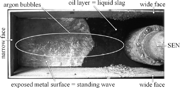
Special oil with suitable viscosity has been employed to simulate the liquid slag-pool in CCS-1. A standing wave was clearly seen during operational tests in CCS-1 when this oil was used at the metal surface in the mould. Figure 10 shows how the oil layer is pushed away from the narrow face due to the flow moving from the narrow face towards the nozzle (confirming also the upper roll flow pattern measured with the ultrasound and Vives probes. Moreover, increasing the casting speed expands the area without slag cover, indicating a proportional increase of velocity at the interface and standing wave intensity.
The presented measurements are a proof of concept for the physical model presented. Subsequently, the model was tested under typical operating conditions for the Continuous Caster No. 4 at SSAB, Luleå. The results were compared to numerical predictions for the same SEN and mould configuration and scaled argon flow-rates. Comparisons of flow-patterns, metal level dynamics (standing wave) and bubble’s exit position along the metal surface were carried out.
5. Results and Validation
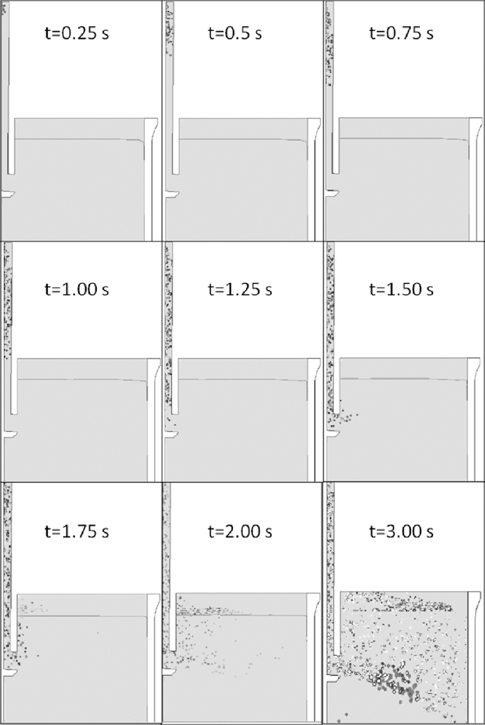
Simulations show that injected argon bubbles travel rapidly to reach the SEN ports (~2 s). A typical bubble distribution for the first 3 seconds after argon injection is shown in Fig. 11. The bubble distribution along the SEN bore is considerably irregular along most of the nozzle height. However, before leaving the nozzle, the bubbles accumulate around the upper port and are dragged into the mould by the metal as it leaves the nozzle.
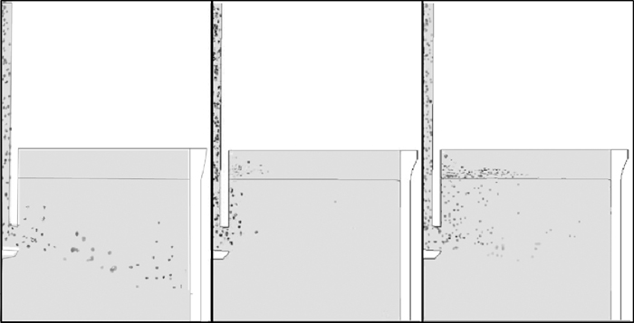
After leaving the port, the bubbles are entrained by the discharging jet for a distance clearly related to the bubble size and argon-flow rate. A variety of tests were carried out to compare FLUENT’s built-in drag and numerical schemes (accuracy control, two-way turbulence coupling, tracking scheme selection, etc.).29) Fully developed gas distributions for some of these tests are presented in Fig. 12.
Results demonstrate clearly that the only approach producing a realistic spreading of bubbles is the DPM+VOF+ additional UDF’s approach (Fig. 12-right). In contrast, the non-spherical drag laws cause total entrainment of bubbles along the discharging jet (Fig. 12-left), whilst the spherical laws cause departure of most bubbles close to the nozzle (Fig. 12-centre). A comparison with observations in the liquid metal model for gas flow-rates used typically during casting shows that in all cases the bubbles have the following behaviour:
• Bubbles leave the metal bulk through the metal surface (opposite to results in Fig. 12-left)
• Bubbles are distributed along the whole metal surface (opposite to results in Fig. 12-centre)
• Although the bubbles exit the metal surface along the whole mould width, a higher amount of bubbles leave the surface close to the SEN; while a lower amount depart through the rest of the surface (in line with results on Fig. 12-right).
Simulations were performed to explore the influence of bubble size and different gas flow-rates in the calculations. For instance, Fig. 13 shows the predicted velocity fields and bubble distribution for 4 and 5 lt/min at constant casting speed; which shows clear differences in bubble departure positions and flow behaviour. The 4 lt/min case produces a more even distribution of bubbles, which are carried deeper into the melt by the discharging jet. These effects are clearly seen through the predicted velocity field (Fig. 13-top), where bubbles leave “high velocity traces” when escaping the jet and reaching the surface. Thus, a lower increase in velocity close to the SEN is observed for the 4 lt/min case. In contrast, the 5 lt/min case leads to bubbles rising closer to the SEN due to enhanced buoyancy and drag forces. This creates higher departure velocities close to the SEN (e.g. dark area adjacent to ports); and subsequent weakening of the discharging jet, which is also shorter and more distorted at higher argon flow rates (Fig. 13-bottom).

Although finer grid sizes are required to capture in detail the effect of bubbles passing through the metal-slag interface (note also that simulations were carried out in 2D), it is possible to deduct that net effect of higher gas flow-rates is the increase of instabilities in the mould due to bubble coalescence and augmented drag. Hence, the grouping of bubbles around the nozzle at higher argon loads would favour their collapse into larger bubbles, which offer a higher resistance to the jet and reduce the number of smaller bubbles entrained deeper into the mould. This mechanism was investigated by taking video sequences during tests in CCS-1 under the same argon flow rates (Fig. 14).

At this stage, comparison between the 2D numerical model and CCS-1 is only qualitative since the actual amount of gas leaving the interface was not measured. Nevertheless, it is the author’s contention that the departure of bubbles along the centreline for CCS-1 can be compared with the 2D simulations in the central plane since bubble departure positions along the central plane are expected to be similar for both cases. This is due to the fact that the entrainment of bubbles is strongly dependent on the discharging jet intensity; while velocities in the thickness direction are thought to have little influence in the entrainment of bubbles. Differences in stability of the metal surface are easily noticeable by comparing the video-sequences for 4 lt/min (left) and 5 lt/min (right) in Fig. 14. Lower argon flow rates produce a more stable flow pattern at the surface, with the formation of the typical upper roll pushing constantly the oil layer towards the nozzle. In this case, argon bubbles depart uniformly along the mould width with smaller bubbles bursting closer to the narrow face; while slightly larger bubbles burst next to the SEN. In contrast, the higher argon flow rate case produces an unstable metal surface with some medium size bubbles bursting at random positions and large bubbles exploding close to the SEN.
Not incidentally, this transition from stable to unstable flow was detected when increasing the argon flow rate higher than 4 lt/min; which is the maximum gas flow rate employed by operators to avoid a “boiling effect in the surface” This boiling effect is known to be detrimental to mould level control due to unstable metal flows (as observed in the simulations and CCS-1). This demonstrates that the numerical methodology developed is predicting accurately the transition point from stable to unstable flow patterns due to argon injection as seen in the liquid metal model CCS-1 and the daily casting practice. Application of these tools to find optimal argon flow rates and improved process windows is an ongoing task by means of parametric studies, further tests in CCS-1 and plant trials.25)
6. Conclusions
A novel numerical technique able to predict the multiphase (steel/slag) flow dynamics coupled with argon injection within the CC mould has been presented. The technique is based on the coupling of the DPM Lagrangian approach, which allows individual tracking of gas bubbles in a continuum phase; together with the Volume of Fluid method for calculation of free surfaces on multiphase flows. The model has been developed with the aim of analysing industrial practices (e.g. argon injection) by comparing results with physical modelling in a Continuous Casting Simulator (CCS-1) and industrial observations. The following conclusions can be drawn from the initial application of these models:
(1) The coupling of the DPM technique to an existing CC model based on the multiphase VOF method has proven possible. This includes the displacement of bubbles across the slag-metal interface and through the slag layers.
(2) The modified DPM+VOF model with additional source terms is the only capable of describing realistically the distribution of bubbles as seen in liquid metal model experiments and the industrial practice.
(3) Both the numerical and physical model presented are capable of matching phenomena observed in the industrial practice such as the “boiling effect” at excessive argon flow rates, which is detrimental to process stability.
(4) The combination of predictions by the developed numerical model and observations in CCS-1 allow a deeper understanding of the mechanisms responsible for achieving stable or unstable flows during casting.
Findings provide enough evidence to consider the DPM+VOF technique as reliable for the analysis of argon injection in Continuous Casting. The model is thus ready for parametric studies and final coupling with heat transfer and solidification on a fully integrated model for Continuous Casting.
Acknowledgements
PRL would like to thank operators at SSAB for fruitful discussions and Mr. Christer Olofsson for support during CCS-1 trials. PJ would like to thank Professor Pär Jonsson at KTH (Stockholm) for continuing support during his M.Sc. and Doctoral studies. PRL and PJ would like to thank Professors K. Nakajima, S. Lohenkilpi and P. Jonsson for their kind invitation and excellent organization of CSSCR 2013 in Helsinki-Stockholm. The research leading to these results has received funding from the European Union’s Research Programme of the Research Fund for Coal and Steel (RFCS) under grant agreement n° [RFSR-CT-2011-00005].
References
- 1) G. Stephens, D. Kirsch, M. Pianezzola, I. Alonso, V. Colla, J. Palacios and T. Lamp: RFSR-CT-2009-00005, European-Comission, Research Fund for Coal and Steel, Brussels, (2012).
- 2) P. Thomas: Mater. Sci. Technol., 21 (2005), 334.
- 3) J. Ciriza, J. Laraudogoitia and G. Alvarez de Toledo: Ironmaking Steelmaking, 30 (2003), 353.
- 4) S. Kunstreich and P. H. Dauby: 4th European Conf. on Continuous Casting, IOM3, London, (2002), 489.
- 5) W. C. Amaral, L. Gimeno, A. Carvalho and F. Vartuli: Conf. Proc. Annu. Symp.on Computer Architecture, ICAF·Pergamon Press, Düsseldorf, (1980), 301.
- 6) R. Aigner and H. Steinruck: Eurotherm, 82 (2005).
- 7) B. Shen, H. Shen and B. Liu: ISIJ Int., 47 (2007), 427.
- 8) P. E. Ramirez-Lopez, P. D. Lee and K. C. Mills: 12th Conf. Modeling of Casting, Welding and Advanced Solidification Processes, TMS, Warrendale, PA, (2009), 61.
- 9) S. Louhenkilpi, M. Makinen, S. Vapalahti, T. Raisanen and J. Laine: Mater. Sci. Eng. A, 413–414 (2005), 135.
- 10) B. G. Thomas and C. Li: Metall. Mater. Trans. B, 35 (2004), 1151.
- 11) B. G. Thomas: Metall. Mater. Trans. B, 33 (2002), 795.
- 12) M. Wu, A. Ludwig and C. Pfeiler: Mater. Sci. Eng. A, Struct. Mater., 413–414 (2005), 115.
- 13) B. G. Thomas, A. Dennisov and H. Bai: ISS 80th Steelmaking Conf., ISS, Warrendale, PA, (1997).
- 14) L. I. Baokuan, T. Okane and T. Umeda: Metall. Mater. Trans. B, 31 (2000), 1491.
- 15) H. Bai and B. G. Thomas: Metall. Mater. Trans. B, 32B (2001), 269.
- 16) P. E. Ramirez-Lopez, P. D. Lee, K. C. Mills, R. D. Morales, A. R. Sanchez-Perez and A. Ramos-Banderas: 6th European Conf. on Continuous Casting, Associazione Italiana di Metalurgia, Riccione, (2008).
- 17) P. E. Ramirez Lopez, P. D. Lee and K. C. Mills: ISIJ Int., 50 (2010), 425.
- 18) P. E. Ramirez-Lopez, P. D. Lee, K. C. Mills and B. Santillana: ISIJ Int., 50 (2010), 1797.
- 19) K. Timmel, S. Eckert, G. Gerbeth, S. F. and T. Wondrak: ISIJ Int., 50 (2010), 1134.
- 20) D. J. Scoones, O. Puetz, U. Sjöström and J. M. Galpin: Rfcs, EUR 20887, Research Fund for Coal and Steel, Brussels, (2003).
- 21) S. R. Higson, P. Drake, M. Lewus, T. Lamp, H. Kochner, P. Valentin, C. Bruch, J. Ciriza, J. Laraudogoitia, J. Björkvall and L. Bergman: EUR 24205, Research Fund for Coal and Steel, Brussels, (2010).
- 22) G. Gerbeth, S. Eckert, K. Timmel and X. Miao: Jim Evans Honorary Symp.: Flow Phenomena in Steel Continuous Casting, Sponsored by TMS, Wiley, NJ, (2010).
- 23) T. Weissenfluh: Int. J. Heat Mass Transfer, 28 (1985), 1563.
- 24) M. Iguchi, M. Takeuchi, H. Kawabata, K. Ebina and Z. Morita: Mater. Trans. JIM, 35 (1994), 716.
- 25) P. E. Ramirez Lopez, J. Björkvall, T. Jonsson, S. Karagadde, P. D. Lee, K. C. Mills, D. Van der Plas, E. Van Vliet, F. Shahbazian, P. Andersson, J. Oppelstrup, C. NIlsson and P. Wikström: RFSR-CT-2011-00005, European-Comission, Research Fund for Coal and Steel, Brussels, (2013).
- 26) J. U. Brackbill, D. B. Kothe and C. Zemach: J. Comput. Phys., 100 (1992), 335.
- 27) J. L. Liow, M. Rudman and P. Liovic: ISIJ Int., 41 (2001), 225.
- 28) R. D. Morales and P. E. Ramirez-Lopez: AISTech Conf. Proc., AIST, Warrendale, PA, (2006), 20.
- 29) ANSYS Fluent, v.12 - User’s Guide, ANSYS Inc., NH, (1995–2007).
- 30) K. Spitzer, K. Schwerdtfeger and J. Holzhauser: Steel Res., 70 (1999), 430.
- 31) P. E. Ramirez Lopez: PhD Thesis, Imperial College London, UK, (2010), 170.
- 32) M. V. Tabib, S. A. Roy and J. B. Joshi: Chem. Eng. J., 139 (2008), 589.
- 33) M. E. Díaz, A. Iranzo, D. Cuadra, R. Barbero, F. J. Montes and M. A. Galán: Chem. Eng. J., 139 (2008), 363.
- 34) D. Zhang, N. G. Deen and J. A. M. Kuipers: Chem. Eng. Sci., 61 (2006), 7593.
- 35) M. Cross, T. N. Croft, G. Djambazov and K. Pericleous: Appl. Math. Model., 30 (2006), 1445.
- 36) E. Olmos, C. Gentric, C. C. Vial and G. Wild: Chem. Eng. Sci., 56 (2001), 6359.
- 37) H. H. Jakobsen: Chem. Eng. Sci., 56 (2001), 1049.
- 38) C. Pfeiler, M. Wu and A. Ludwig: Mater. Sci. Eng. A, Struct. Mater., 413–414 (2005), 115.
- 39) H. Bai: Metall. Mater. Trans. B, 32 (2001), 707.
- 40) S. W. P. Cloete, J. J. Eksteen and S. M. Bradshaw: Prog. Comput. Fluid Dy., 9 (2009), 345.
- 41) J. E. Olsen and S. W. P. Cloete: 7th Int. Conf. on CFD in the Minerals and Process Industries, CSIRO, Melbourne, (2009).
- 42) S. Cloete, J. E. Olsen and P. Skjetne: Appl. Ocean Res., 31 (2009), 220.
- 43) M. Iguchi, T. Chihara, N. Takanashi, Y. Ogawa, N. Tokumitsu and Z.-i. Morita: ISIJ Int., 35 (1995), 1354.
- 44) N. G. Deen, T. Solberg and B. H. Hjertager: Chem. Eng. Sci., 56 (2001), 6341.
- 45) J. L. Xia, T. Ahokainen and L. Holappa: Scand. J. Metall., 30 (2001), 69.