Regular Article
Growth of Secondary Dendrite Arms of Fe–C Alloy during Transient Directional Solidification by Phase-field Method
2014 Volume 54 Issue 2 Pages 430-436
Details
2014 Volume 54 Issue 2 Pages 430-436
Due to the variations in the local solidification conditions in typical industrial casting processes, dendrites grow under transient rather than steady-state conditions. In this study, the phase-field method was used to study the evolution of secondary dendrite arms of Fe-0.3 wt.% C alloy during transient directional solidification imposed by decreasing the pulling velocity. We find that the dendrite under transient growth conditions is different from the steady-state dendrite, with smaller selection parameter σ* and the dendrite envelope inside the parabola scaled by the tip radius. The secondary arms undergo a ripening process in which other secondary arms remelt by shrinking from their tips, rather than by detachment from the primary stalk. The surviving arms are finer than those found under steady-state growth conditions, and the size of the surviving arms decreases with decreasing growth velocity.
Dendrites are the predominant microstructural feature of cast metals, and the mechanical properties of the product depend strongly on the length scale and segregation pattern. Thus, understanding the shape and the length scale of a dendrite has been of interest in the casting field. Over the last few decades, a much better knowledge of steady free-growth dendrite has been obtained through the studies.
There are three regimes of a free-dendritic growth along the distance xtip from the primary tip:
(1) The smooth tip regime free of secondary arms (or side branch) with xtip < 7–10 Rtip where Rtip is the tip radius. According to the solvability theory,1,2) the anisotropy of the solid/liquid (S/L) interfacial energy has a significant effect on the shape of this regime. The steady-state Rtip is coupled to the steady-state tip velocity Vtip by the selection parameter
| (1) |
(2) The initial secondary arm regime where the arms with small amplitude grow out on the primary stalk. This regime could be up to xtip < 30 Rtip, and the connection of the arms tips forming an envelope whose form can be expressed as6,7,8,9,10)
| (2) |
(3) The non-linear arming regime where the arms are under the complex ripening process during which the secondary arms of large size become coarser and otherwise remelt.11) Although the evolution is complex, Beckerman et al.9,10) found for the steady free-growth dendrite of SCN-acetone that the envelope of the arms can be still expressed in the form of Eq. (2) when xtip is as large as 100 Rtip.
Under directional solidification conditions, the solidified structure is not an isolated dendrite, but rather a dendritic array with another additional length scale, i.e. primary spacing λ1. Experimental measurements12) showed that λ1 is not a fixed value under a given thermal gradient G and pulling velocity Vp, but instead varies in a finite range, which also has been modelled numerically by Hunt et al.13,14,15) However, the steady-state Rtip does not change with λ1,12,14,15,16) which thus implies that secondary arms largely contribute to the adjustment of the primary spacing. By contrast, direct observation of the secondary arm evolution under the steady constrained dendrite is rarely reported.
In practical casting processes, dendrites grow under transient growth conditions, i.e., where G and Vp evolve during growth.17,18,19,20,21,22) The occurrence of arm detachment (fragmentation), which is one mechanism for columnar-to-equiaxed (CET) transition,23,24) is reportedly more likely to happen under transient growth conditions. Lu et al. observed in SCN–H2O that the ripening process under steady-state growth does not involve significant detachment of side branches except for a very long time (> 1 h).16) However, over 30% of the secondary arms were detached within 20 mins when the pulling velocity was decreased after the steady state was achieved from an initially larger velocity.25) These results indicate that evolution of the secondary arms during the transient growth condition is different from the steady-state behaviour. Therefore, in this study we aim to shed light on the secondary arm behaviour under transient growth conditions.
The phase-field (PF) method is commonly used to simulate dendritic growth because of its capability of tracking the S/L interface with high resolution at the micrometre scale.26) Compared to the experimental techniques with comparable resolution to PF method, such as x-ray synchrotron radiation,24) the PF method is of lower cost and easier data measurement. Several problems on dendritic growth, such as the orientation selection influenced by the anisotropy of S/L interfacial energy,27,28,29) has been studied by the PF method.
In this work, we extended the PF code developed by Jeong et al.,30,31) to include finite solid diffusivity32) following the model proposed by Ohno and Matsuura.33,34) It is thus applicable to industrial Fe–C alloys where the solid diffusivity of C solute is comparable to its liquid diffusivity.35) In this study, the growth of secondary dendrite arms of Fe-0.3 wt.% C alloy during transient directional solidification imposed by decreasing the pulling velocity was investigated using the PF method. Comparisons were made between the steady-state and transient dendrites by quantitatively examining the dendrite envelope and by observing the coarsening and remelting of the secondary arms. In the following sections, we first describe the PF model, and then proceed to examine these results.
The PF method introduces a continuous variable ϕ that identifies the phases:26) ϕ = +1 in solid, ϕ = –1 in liquid, and intermediate values correspond to the S/L interface. Thus, the S/L interface is treated as a diffuse field with a non-zero width (w). The thin-interface PF model for binary directional solidification originally proposed by Echebarria et al.36) is used in the simulations. In this model, a dimensionless variable u is introduced to represent the concentration C, defined as
| (3) |
The evolution equation for ϕ and C for directional solidification are
| (4) |
| (5) |
| (6) |
In Eq. (5),
| (7) |
| (8) |
The S/L interfacial energy γsl and its anisotropy (i.e. its dependence on the interface normal
| (9) |
| (10) |
The dynamics of sidebranch initiation has been attributed to selective amplification of noise,38,39) and to deterministic oscillations near the dendrite tip.40,41) In this work, we do not add noise to the equations. However, there remains some residual grid noise that contributes to the growth of sidebranches in our simulations. These sidebranches tend to start farther from the tip than they would if noise were to be included. Thus, our simulations do not address the question of differentiating between these two mechanisms. Nevertheless, our focus here is on the evolution by coarsening of arrays of sidebranches, which is not affected by their origin.
2.2. Parameter SelectionThe nominal composition of the model Fe–C alloy is C0 = 0.3 wt.%, and the material properties used in the simulations are shown in Table 1. There is no accepted experimental value in the literature for the anisotropy in S/L interfacial energy for Fe–C alloys.42) In our simulations, the input S/L interfacial energy and its anisotropy listed in Table 1 were obtained from the MD modelling provided by Liu et al.43) We used G = 150 K/mm and Vp = 8/mm for the base case, corresponding to the conditions at one point of the weld pool obtained by the front-tracking modelling carried out by the MintWeld project partners at University College Dublin National University of Ireland, Ireland.44) We used w = 0.08 μm, which was determined by numerical experimentation to give consistent converged results.
| Materials Properties | ||
|---|---|---|
| Value | Source | |
| Equilibrium partition coefficient | 0.176 | thermodynamic calculation |
| Liquidus slope (K/(wt.%)) | –80 | thermodynamic calculation |
| Liquid diffusivity (m2/s) | 2×10⁻⁸ | 45) |
| Solid diffusivity (m2/s) | 5.57×10⁻⁹ | 45) |
| Interfacial energy(J/m2) | 0.164 | MD calculation |
| Anisotropy a1 | 0.0288 | MD calculation |
| Anisotropy a2 | –0.000612 | MD calculation |
Two-dimensional (2D) simulations were performed in this study by using thin samples with Lx = Ly >> Lz, as the transition from the 3D to 2D was observed due to the refinement in one direction.31) Because of the cubic symmetry, only 1/4 cylinder seed of radius r0 = 4w and height h = Lz was placed at the origin to initiate the solid. G and Vp were imposed along the x-axis, which was also parallel to the <001> axis of the crystal. The length of y-axis was Ly = 1/2 λ1 where λ1 was the primary spacing of the dendrite/cell array. Because the λ1 varies in a finite range under given directional solidification conditions,13,14,15) we examined a variety of spacings. The secondary arms were suppressed when λ1 was less than 15.36 μm. In the results shown below, λ1 = 40.96 μm was selected, which allowed the outgrowth of secondary arms. Symmetry boundary conditions were imposed on the x-y face and x-axis was long enough that the solutal boundary layer ahead of the tip never approached the far boundary.
Steady state was reached at time t = 0.009 s for Vp = 8 mm/s, defined as when Vtip = Vp. The morphology at t = 0.009 s is shown in Fig. 1. The sharp shape of the primary tip indicates that the obtained solidified structure under the concerned condition is dendritic rather than cellular. It can be seen that the secondary arms initially grew in different directions with different sizes that were determined during the later ripening process.
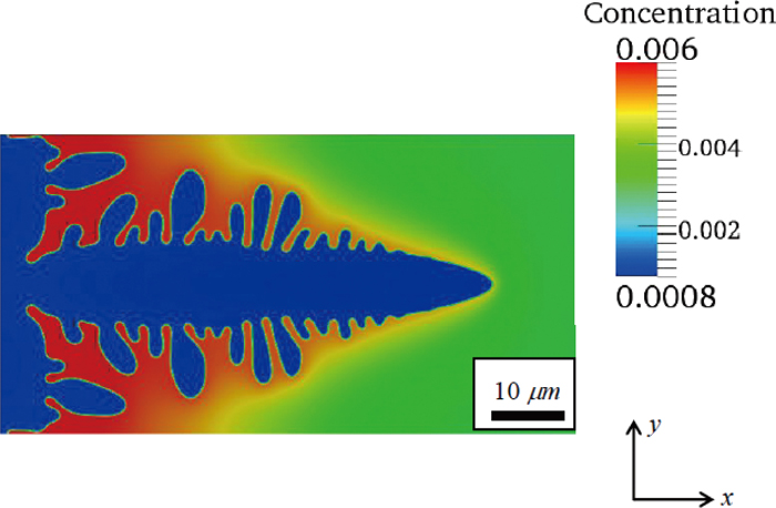
The morphology at t = 0.009 s, when the dendritic growth had reached steady state at the initial higher velocity Vp = 8 mm/s.
Transient growth conditions were then imposed by decreasing the pulling velocity from Vp = 8 mm/s to Vp = Vf after the dendritic growth reached the steady state at t = 0.009 s. We examined several values for Vf: 4 mm/s, 2 mm/s to 1 mm/s. Figure 2 shows the evolution of Vtip vs. t for the various Vf, indicating that the dendrite begun to evolve under the transient condition due to the change in Vp. As shown in Fig. 2, Vtip gradually approached Vf , whereupon a new steady state was achieved for the new pulling velocity. Our concern is the transient stage and therefore we stopped the calculations at that point The evolution of the dendritic growth during the transient growth condition with an emphasis on the secondary arms will be discussed below.

Evolution of tip velocity after the pulling velocity was decreased during the dendritic growth. (Online version in color.)
The plots of Rtip vs. t under different conditions given in Fig. 3 show that Rtip went into the steady state at time t = 0.009 s for the initial Vp = 8 mm/s and kept as constant if it continued to grow under steady state where Vp was not changed afterwards (dash line). The steady-state Rtip obtained by the PF method is 0.66 μm, close to the value of 0.67 μm given by the KGT prediction.46) The closeness of the agreement between the PF and KGT results is probably fortuitous. By contrast, when the Vp was decreased to a lower value Vp = Vf after t = 0.009 s, as shown in Fig. 3, the Rtip began to increase corresponding to the decrease in the Vtip (Fig. 2). At the same solidification time, the Rtip is smaller at the higher Vf while Vtip is larger as can be seen in Fig. 2. The trends of Rtip varying with Vtip under the steady-state and transient growth conditions all qualitatively complied with that predicted by solvability theory.1,2)

Evolution of tip radius under various growth conditions. (Online version in color.)
Quantitatively, the selection parameter σ* was examined and plots of σ* vs. t during transient growth conditions are shown in Fig. 4. The selection parameter obtained in steady-state growth did not persist under the transient growth condition. For each value of V, the selection parameter began to decrease after Vp was decreased, with a larger decrease for larger velocity changes. Thus, we find that the selection parameter is not constant when Vp changes.

Evolution of selection parameter under various growth conditions. (Online version in color.)
With the primary stalk advancing during the dendritic growth, new secondary arms grow out with distance from the primary tip, and the arms away from the tip undergo a complex ripening process, where the secondary arms grow competitively with their neighbours. Some of the secondary arms survive and become coarser, whereas others remelt. The dendrite envelope is commonly used to characterize the complex morphology including the secondary arms.5,8,9,10) This envelope consists of the smooth contour of the primary tip region and the connection of the ‘active’ (or surviving) arm tips.
The dendrite envelopes at different times on the steady-state evolution are plotted in Fig. 5 for various times, with the primary tip always located at the origin. It can be seen that the contours of the tip regime before the secondary arms exactly overlap, meaning that the primary tip regime evolves in a shape-conserving manner. By contrast, secondary arm tips at different times were located at different positions. However, if the connection of those tips (dendrite envelope) rather than the separate tips, were examined, it can be seen that the dendrite envelopes at different times overlap indicating that the dendrite envelope evolves in a shape-conserving manner, in agreement with the experimental observation on the secondary arm evolution of SCN-acetone under steady-state free growth.9,10)

The dendrite envelopes at different times on the steady-state evolution with the primary tips located at the origin. (Online version in color.)
As mentioned in the Introduction, the geometric parameters of the dendrite can be scaled by the Rtip, and thus the dendrite envelopes in Fig. 5 were re-plotted with xtip and y scaled by Rtip obtained by phase-field simulation. The result is shown in Fig. 6. Figure 6(a) is limited to the tip regime, which also includes a parabola expressed as

The dendrite envelopes at different times on the steady-state evolution located in the coordinate system scaled by the tip radius. (Online version in color.)
For the regime outlined by the secondary arm tips, the least-squares fit from Eq. (2) shows that for 10 < xtip/Rtip < 50, the secondary tip positions can be correlated by
| (11) |
As discussed above, the dendritic envelope at different times during steady-state evolution can be scaled by the steady-state Rtip using the reported expressions (Eqs. (1) and (2)) when xtip/Rtip < 50. To compare the computed shapes at various times, the geometry at each time was scaled by the value of Rtip at that time, and each dendrite was translated such that its tip corresponded to xtip/Rtip = 0.
Figure 7 is the dendrite envelope at time t = 0.03 s under the transient growth condition for Vf = 1 mm/s scaled by the value Rtip = 2.5 μm. The parabola was also plotted in the same figure for comparison. It can be seen that the contour at the tip regime does not fit with the parabola again but instead is included by the parabola. Surprisingly, the regime of the dendrite envelope with the secondary arms growing out is also inside in the parabola, as shown in Fig. 7. It is different from the steady-state dendrite where the dendrite envelope is outside the parabola, indicating that the development of the dendrite envelope is retarded with the increasing tip radius under the transient growth condition. It may be because Rtip increased much faster than that predicted by the solvability theory as shown in Fig. 4.

The dendrite envelope at time t = 0.03 s under the transient growth condition for Vf = 1 mm/s located in the coordinate system scaled by the tip radius. (Online version in color.)
Figure 8 shows the evolution of the secondary close to the dendrite bottom at time t = 0.012 s and t = 0.030 s under steady-state growth conditions. As shown in Fig. 8(a), the secondary arms at earlier time are in different orientations as observed in the experiments,9,10) indicating that the growth direction of the secondary arms after their outgrowth at a distant from the tip is not in the preferred orientation determined by the S/L interfacial anisotropy, which is different from the behaviour of the primary stalk.

Morphologies close to the dendrite bottom at time t = 0.012 s and t = 0.030 s under the steady-state growth condition. (Online version in color.)
However, through competitive growth, as shown in Fig. 8(b), the surviving secondary arms (marked by the numbers) become coarser with almost the same orientation, which should be the preferred orientation determined by the anisotropy in interfacial energy. Thus it indicates that the surviving secondary arms are those which grew in the preferred orientations and those relatively deviated from the preferred orientations remelted during the competitive growth. It can be seen that the preferred orientation is not vertical to the primary stalk but tilted towards <110> around 12 degrees. The tilting of the secondary arms can be attributed to the inclusion of the secondary anisotropy coefficient (a2 in Eq. (9)) in the simulations, which gives additional preferred orientation <110>,28) as well as the fact that the solute field is not parallel to the pulling direction. It can also be seen that the arms between those surviving arms in Fig. 8(a), which are smaller than their neighbours, disappeared after competitive growth. The detailed manner in which they remelted will be discussed further in Section 3.4.
Figure 9 shows the morphologies after competitive growth of secondary arms under the transient growth condition for various Vf. The morphology obtained under the steady state shown in Fig. 8(b) was also plotted in Fig. 9 for comparison. Note that the morphologies shown in Fig. 9 were not at the same solidification time because the morphologies at the same solidification time under various conditions are not in the same ripening stage, and thus are not comparable. Therefore we compared the surviving secondary arms at the solidification times when the arms between those surviving arms had almost disappeared.

Morphologies close to the dendrite bottom after the competitive growth of secondary arms under various growth conditions.
Figure 9 shows that the surviving secondary arms under the transient growth conditions are those that survived under the steady-state growth condition. Thus whether under the steady-state growth condition or under the transient growth condition, the secondary arms with the preferred orientations survived and became coarser during the competitive growth. However, it can be found that the surviving arms were finer under transient growth conditions than under constant growth velocity, and the necklaces connecting the arms to the primary stalk were finer. Furthermore, the size of the surviving arms decreases with decreasing growth velocity as shown in Fig. 9, indicating that it is the decrease in the tip velocity that leads to the finer secondary arms.
3.4. Remelting of the Secondary ArmsThe detachment of the secondary arms is related to the question on how the secondary arms remelted during the competitive growth; the detachment will happen if the remelting of the secondary arms occurs at the necklace through which the secondary arms are connected to the primary stalk. Therefore, we examined the remelting process of all the secondary arms that happened in the simulations under both steady-state and transient growth conditions. Only one manner of remelting is observed and the typical remelting process is shown in Fig. 10 in which the secondary arms between the surviving arms gradually remelted with time.

Typical remelting process observed in the simulations. In this case, the dendritic grew under the transient growth condition with Vf = 1 mm/s.
Initially at time t = 0.009 s (Fig. 10(a)), several secondary arms existed between the surviving arm marked as 1 and 2. During the growth of the secondary arms, solute was rejected and accumulated in the grooves between the surviving arms, and thus it can be seen that the liquid concentration around the surviving arms was lower than that around the arms between them. The higher solute concentration means lower melting temperature, and the arms remelt once the local temperature is higher than the local melting temperature. Thus it can be seen from Fig. 10(b) that the smaller two arms have firstly entirely remelted at time t = 0.015 s. With time evolving, the other relatively larger arms between the arm 1 and 2 gradually remelted while the surviving arms 1 and 2 became coarser as discussed earlier.
Importantly, Fig. 10 demonstrates that the remelting of the secondary arms started from the tip with decreased height while the necklace width became coarser. When it was totally remelted, the coarser necklace became part of the primary stalk. Thus, the secondary arms remelted by shrinking from the tip rather than by detachment from the primary stalk at the necklace.
As discussed above, the detachment of the secondary arms was not observed in our study. In the literature, besides the transient growth condition, the detachment was observed when the flow was also included.47) Note that in the experiments carried out by Lu et al.,25) the flow was an uncontrolled factor. Therefore, if the flow is a necessary factor in the occurrence of the detachment of the secondary arms under the transient growth condition needs further study.
In this study, the phase-field method was used to study the evolution of secondary dendrite arms of Fe-0.3 wt.% C alloy during transient directional solidification imposed by decreasing the pulling velocity. Dendrite envelope, the coarsening and remelting of the secondary arms under the transient growth condition were concerned. Under the transient growth condition with the tip velocity decreasing,
(1) The selection parameter σ* is smaller than that under the steady-state condition.
(2) The dendrite envelope cannot be scaled by the tip radius and the part of the dendrite envelope with secondary arms is within the parabola, which is different from the steady-state dendrite envelope where the dendrite envelope can be fitted by the reported expressions within xtip/Rtip < 50 and the part with secondary arms is within the parabola.
(3) The surviving secondary arms, which became coarser through the ripening process, are finer than those under steady-state growth condition. Furthermore, the size of the surviving arms decreases with decreasing growth velocity.
(4) The secondary arms remelted by shrinking from the tip. Detachment from the primary stalk at the necklace was not observed.
This research work is supported by the European Commission as part of the FP7 programme, as the project, Modelling of Interface Evolution in Advanced Welding; contract number NO. NMP3-SL-2009-229108.