Note
Re-Occurrence Time of Swirl Motion Caused by Transient Increase in Water Bath Depth
2014 Volume 54 Issue 8 Pages 1994-1996
Details
2014 Volume 54 Issue 8 Pages 1994-1996
The swirl motion of a bubbling jet generated in a bottom blown bath ceases temporarily under a certain gas injection condition due to a sudden increase in the bath depth. Re-occurrence time of the swirl motion, Ts,sa, is defined as the period from the sudden supply of water into the bath to the moment at which re-occurrence of the swirl motion is observed in the bath. Measurements of Ts,sa, are carried out to propose its estimation method.
A liquid jet involving many bubbles in it is defined as a bubbling jet. This type of jet is formed, for example, above a bottom injection nozzle placed in a cylindrical bath. The bubbling jet generated does not always rises straight upward thus swirls around the vessel axis under a certain injection condition.1,2,3,4,5,6) Previous experimental and numerical investigations revealed the occurrence condition, period, amplitude, starting time and stopping time of the swirl motion.4,5) Mixing time also attracted the interest of researchers in materials engineering. Application of a bubbling jet has been expected in the steelmaking industry because of its high mixing ability. Unfortunately, sloping of molten steel and oscillation of the reactor containing the molten steel become serious in the presence of the swirl motion. Considering these circumstances, swirl motion is not employed in the current steel refining processes at the present stage. Findings obtained by other researchers should be referred to Refs. 4) and 5).
The bath depth, HL, and gas flow rate, Qg, were kept constant with time in the previous studies of the swirl motion of a bubbling jet. Namely, only steady state swirl motions were treated previously. In practical applications however processes are often operated under unsteady state conditions. For example, the bath depth is sometimes increased in a very short time due to sudden supply of liquid or decreased with time due to abrupt drainage of the liquid contained in the bath. Another example is the case that the gas flow rate is changed in the processing operations. It is not clear whether or not the bubbling jet continues to swirl around the vessel axis during such changes in the bath depth and gas flow rate.
The objective of this study is to investigate the behavior of a swirl motion under a sudden increase in the bath depth using a water model. The swirl motion is found to be ceased due to sudden supply of a great amount of water into the bath because the bath is significantly disturbed. After a while, it occurs again as long as the final bath depth is kept in the preferable occurrence region of the swirl motion.
Re-occurrence time of the swirl motion, Ts,sa, is defined as the period from the sudden supply of water to the moment at which re-occurrence of the swirl motion of the bubbling jet is observed in the bath. An estimation method of the re-occurrence time will be proposed.
Figure 1 shows a schematic of the experimental apparatus. The diameter and depth of the bath were denoted by D and HL, respectively. The diameter and height of the vessel were D = 0.200 (m) and H = 0.400 (m), respectively, and the inner diameter of the nozzle was dni = 4.0 × 10⁻³ (m). The bath depth, HL, was varied over a wide range in the preferable occurrence region of a swirl motion. According to the previous investigations,4,5) the bath surface swirls around the vessel axis together with the bubbling jet, while the liquid near the bottom corner of the vessel does in the opposite direction to satisfy the conservation of angular momentum. The occurrence region of the swirl motion is schematically shown in Fig. 2. A swirl motion occurs in the region enclosed with the following four sub-boundaries.7)

Schematic of swirl motion in a cylindrical bath (A: amplitude of swirl motion).

Occurrence region of swirl motion.
(a) Sub-boundary (1)
| (1) |
(b) Sub-boundary (2)
| (2) |
(c) Sub-boundary (3)
| (3) |
(d) Sub-boundary (4)
| (4) |
In the occurrence region shown in Fig. 2 measurements were carried out at several gas flow rates. A predetermined volume of water was supplied from the upper part of the vessel into the bath with a beaker at every gas flow rate. The water supply position was denoted by Hws and kept at 0.400 (m). The water penetrated into the bath from the central part of the bath surface. The time required for the complete water supply was Tin = 1.5 ± 0.2 (s). The bath depth, HL, was varied from the initial value, HLi, to the final value, HLf. The experimental conditions were selected near the central part of the occurrence region in Fig. 2 because both the swirl motions at the initial and final stages are very stable there. The bath depth, HL, was varied from 0.070 (m) to 0.170 (m) (HL/D = 0.35 – 0.85) and the gas flow rate, Qg, was increased from 100 × 10–6 (m3/s) – 700 × 10–6 (m3/s). The occurrence of a steady swirl motion was judged by visual observation, as described in the previous paper.6) Measurements were repeated more than 5 times under every experimental condition.
It is useful for a better understanding of the re-occurrence time of a swirl motion to mention about the measured data on the period, Ts (s), and the starting time of the swirl motion, Ts,s (s). The swirl period is known to be in good agreement with the period of the rotary sloshing. The same conclusion was obtained in this experiment for Ts. The starting time of swirl motion, Ts,s, is defined as the period from the start of gas injection into a bath to the moment at which a steady swirl motion of a bubbling jet appears in the bath. Empirical equations for the starting time, Ts,s, are expressed as:6)
| (5a) |
| (5b) |
| (6) |
The above-mentioned study6) represented that the measured values of the staring time are approximated by Eq. (5) within a scatter of about ±60%. The measured values obtained in this study were predicted by Eq. (5) within the same degree of scattering.
3.2. Condition Describing the Temporal Cessation of Swirl Motion Due to Sudden Supply of WaterThe potential energy of the water, Ep (J), is expressed as follows:
| (7) |
| (8) |
When the ratio of the potential energy, Ep, to the energy introduced by injected gas, Eg, is greater than a certain critical value, the swirl motion would cease because the flow in the bath is significantly disturbed. The ratio of Ep to Eg is therefore considered to be a measure for describing the temporal cessation of the swirl motion.
| (9) |
Table 1 shows the relationship between this ratio, Ep/Eg, and the behavior of swirl motion. According to our limited data for Qg = 460 × 10–6 (m3/s) and HLi = 0.070 (m), the critical value is around 4. Meanwhile, the swirl motion for HLi = 0.080 (m) and HLf = 0.110 (m) does not cease even for Ep/Eg smaller than 4. This may be because that Eq. (8) is not satisfied under the real condition as a part of the input gas energy, Eg, lost in the atmosphere. That is, the input gas energy is not completely transferred to the water in the bath. The critical value of Ep/Eg is therefore in relation to the process parameters such as D, HLi, Qg, and dni in a complex manner. Further investigations are, of course, desirable to precisely determine the critical value.
| Gas flow rate Qg (×10–6m3/s) | Initial and final bath depths HLi (m) and HLf (m) | Energy ratio Ep/Eg | Temporal cessation of swirl motion (○: yes, ●: no) |
|---|---|---|---|
| 460 | 0.070, 0.080 | 2.0 | ● |
| 460 | 0.070, 0.090 | 3.8 | ● |
| 460 | 0.070, 0.095 | 4.6 | ● , ○ |
| 460 | 0.070, 0.100 | 5.3 | ○ |
| 100 | 0.080, 0.110 | 21.2 | ○ |
| 220 | 0.080, 0.110 | 9.6 | ○ |
| 340 | 0.080, 0.110 | 6.2 | ○ |
| 460 | 0.080, 0.110 | 4.6 | ○ |
| 700 | 0.080, 0.110 | 3.0 | ○ |
Figure 3 shows the relationship between the re-occurrence time, Ts,sa (s), and gas flow rate, Qg. The re-occurrence time decreased monotonically with an increase in the gas flow rate, Qg. This tendency is very similar to the starting time of swirl motion, and hence, the re-occurrence time is considered to be closely associated with the starting time. Figure 4 indicates that the presently measured values of Ts,sa are well correlated by this arrangement method and Ts,sa is approximately equal to the starting time of swirl motion as:
| (10) |
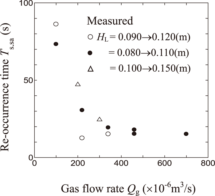
Re-occurrence time of swirl motion, Ts,sa, with gas flow rate, Qg.

Comparison of re-occurrence time of swirl motion, Ts,sa (s) with Ts,s (s) calculated from Eq. (5).
The results obtained under the present experimental conditions can be summarized as follows:
(1) The ratio of the potential energy of supplied water to the input gas energy, Ep/Eg, was introduced to describe the temporal cessation of a swirl motion.
(2) The re-occurrence time of swirl motion, Ts,sa, was approximately equal to the starting time of swirl motion, Ts,s.