Abstract
The 150 year history of the Japanese steel industry dates from the first western blast furnace, which was built by T. Ohashi in 1857. Modern blast furnace operation at integrated steel works in Japan started in 1901 with the first blow-in of Higashida No. 1 blast furnace at Yawata Steel Works. Throughout the prewar and postwar periods, the steel industry has supported the Japanese economy as a key industry which supplies basic materials for social infrastructure and development.
After the period of recovery following the destruction caused by World War II, Chiba Works of Kawasaki Steel Corporation (now JFE Steel Corporation) was built and began operation in 1953 as the first integrated steel works in the Keiyo Industrial Region after the war. During Japan’s period of high economic growth, many coastal steel works with large blast furnaces having inner volumes of more than 3000 m3 and even 5000 m3 were built to enable efficient marine transportation of raw materials and steel products. Japanese steel makers introduced and improved the most advanced technologies of the day, which included high pressure equipment, stave cooler systems, bell-less charging systems, etc. As a result, Japanese steel works now lead the world in low reducing agent rate (RAR) operation, energy saving, and long service life of blast furnaces and coke ovens.
Following the Oil Crises of the 1970s, the Japanese steel industry changed energy sources from oil to coal and implemented cost-oriented operation design and technology. In 2012, the Japanese steel industry produced approximately 80 million tons of hot metal from 27 blast furnaces, including large-scale furnaces with inner volumes over 5000 m3. During this period, the industry has faced many economic and social challenges, such as the high exchange rate of the yen, oligopoly in the mining industry, global warming, and the surge in iron ore and coal prices driven by the rapid growth of the BRICs. The industry has successfully responded to these challenges and maintained its international competitiveness by developing advanced technologies for pulverized coal injection, expanded use of low cost iron resources, recycling for environmental preservation, and CO2 mitigation.
In this paper, the prospects for ironmaking technologies in the coming decades are described by reviewing published papers and looking back on the history of developments in ironmaking during the last 100 years.
1. Introduction
As a key industry that supplies steel products supporting social infrastructure, the Japanese steel industry has supported the development of the Japanese economy throughout the prewar and postwar periods. Blast furnace operation in an integrated steel works began in 1901 when Higashida No. 1 blast furnace was blown in at Yawata Steel Works. After the postwar reconstruction period, a large number of coastal steel works were constructed and a transition to larger blast furnaces was carried out during Japan’s period of high economic growth. High pressure equipment, stave cooler systems, bell-less charging systems, and other world’s most advanced technologies were actively introduced, improved, and developed, leading to the establishment of low reducing agent rate (RAR) operation and other globally-renowned operation technologies.
Low RAR operation1,2,3) is an important index of blast furnace development, and Japan achieved a world record low RAR of 396 kg/thm3) in 1981. In response to subsequent economic and environmental trends, the steel industry has taken on the role of a world leader4) in driving technological development in various fields of the steel production process, from environment-friendly technologies such as technologies for using low-cost raw materials and reducing agents5,6,7,8,9,10,11,12,13,14,15) (including low Si operation technology16,17,18,19,20,21,22,23,24,25,26,27) and high rate pulverized coal injection28,29,30,31,32,33,34,35,36,37,38,39,40,41,42,43)), recycling of waste plastics,44,45) and processing of ironmaking dust46,47,48,49,50,51) to high productivity operation technologies to meet demand for higher production.52) The Japan steel industry is also a world leader in plant engineering, with numerous achievements in connection with longer equipment service life, enlargement of facilities, energy and labor saving, and short-period revamping,53,54,55,56) and is actively developing CO2 emissions reduction technologies57,58,59,60,61,62) to meet the greenhouse gas reduction goals specified in the Kyoto Protocol.
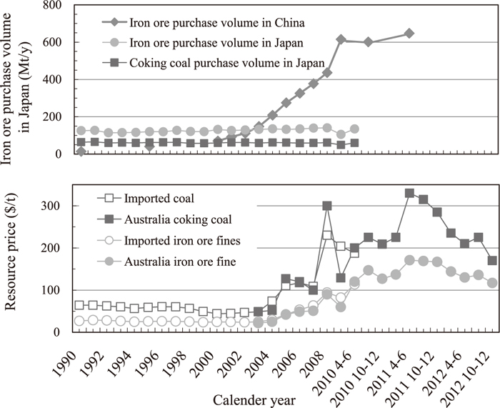
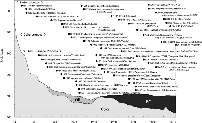
In the past ten years, however, the business environment of the steel industry has undergone large changes, due in part to the global-scale consolidation and reorganization of both resource companies and steel companies and increased crude steel production in China. Since 2000, resource companies have been reorganized into the three top companies of Rio Tinto, Vale, and BHP-Billiton. Moreover, because of the increase in imports for increased crude steel production in China, resource prices have soared since 2002 and are now fluctuating widely within a range three to six times the previous cost level (Fig. 1). The large impact of raw material costs on steel prices also means that development of resource flexibility technologies is a more critical issue than in the past.
Integration of the global steel industry has progressed since around 2000 with the aims of expanding scale and rationalization, resulting in the establishment of ArcelorMittal, Tata Steel which has advanced into Europe, and JFE Steel and Nippon Steel and Sumitomo Metal in Japan. Global crude steel production in 2012 was 1.55 billion tons, about half of which (717 million tons) was produced by China (Fig. 2). In the 1970s, four Japanese steel makers ranked in the top ten companies in crude steel production. However, in recent years, six Chinese companies have entered the top ten, due in part to integration of companies in China (Table 1). The rapid expansion of production in China in the past ten years follows on Japan’s period of rapid economic growth in the 1960s and 1970s, when Japan became one of the world’s leading industrial countries through introduction of advanced technologies from abroad. A review of this period of history will serve as a reference for overseas strategy in the future.
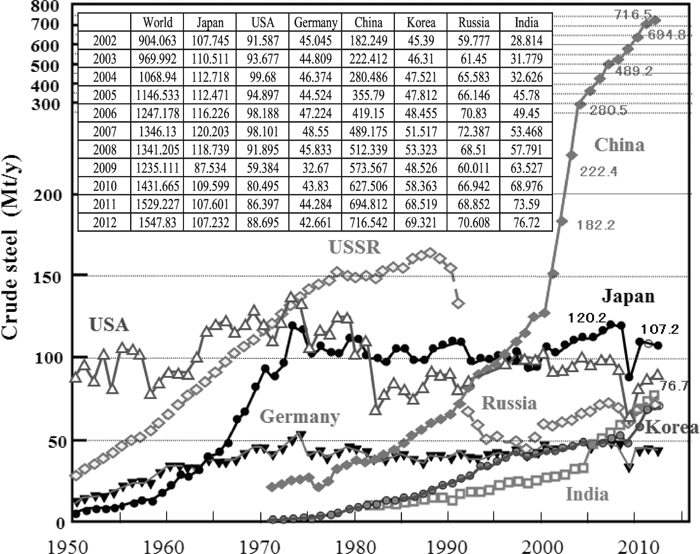
Table 1. Transition of crude steel production by company.
Taking this Commemorative Issue of the 100th volume of Tetsu-to-Hagané as an opportunity, the followings provide a comprehensive review of the history63,64,65,66,67,68,69,70,71,72,73,74,75,76,77,78,79,80,81,82,83,84,85,86,87,88,89,90,91) of the development of ironmaking technology in Japan from 1857, when the first western-style blast furnace began operation, to the present. Technologies which were introduced and refined into original technologies are presented, providing a general summary of the representative lineage of the technologies pursued by our predecessors, and the prospects for next-generation technologies are also examined.
2. History of Ironmaking Technology Development
2.1. Introduction of Modern Ironmaking Technology
Historically, iron was produced in Japan by a small-scale ironmaking method called the tatara92) process with iron sand as the main raw material . Use of the blast furnace process93) began on December 1, 1857 following the construction of a western-style blast furnace in Kamaishi by T. Oshima. In commemoration of this event, December 1 was designated as Iron Memorial Day in 1958. Regarding the fact that western-style blast furnace technology was introduced by inexperienced engineers, including Oshima himself, Tate94) infers that “One of the factors supporting this success is that, in addition to Oshima’s outstanding abilities, the traditional ironmaking process with iron sand was established, even within the framework of Japan’s traditional tatara method, as a molten iron manufacturing method, and the standard for operational conditions was applied to the furnace.”
Figure 3 shows a comparison of the history95) of ironmaking technology in Europe and Japan. The period from the trial introduction of modern ironmaking technology, which started with the construction of a reverberatory furnace in the closing days of the Tokugawa shogunate, to the final establishment of an integrated ironmaking process with the founding of the government-operated Yawata Steel Works in 1910 was described by Ohashi95) as a rapid modernization process that compressed the 400 year history of ironmaking in Europe into only 50 years in Japan.96)
2.2. From the Establishment of Blast Furnace Operation at Integrated Steel Works to the End of the Second World War (World War II)
Like the world’s other major steel manufacturing countries, Japan constructed steel works in resource-producing areas, adjacent to the Kamaishi Iron Mine in Iwate Prefecture and the Chikuho coalfield in Kyushu and the Ishikari coalfield (Sorachi and Yubari coalfields) in Hokkaido. In this process, particular importance was placed on the availability of coal as the main reducing agent.
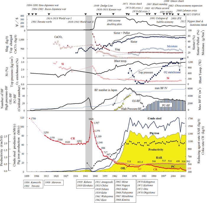
Planning for the government-operated Yawata Steel Works, which was Japan’s first integrated steel works, was carried out in 1894 at the outbreak of the Sino-Japanese war, and operation began with the blow-in of Higashida No. 1 blast furnace (inner volume: 495 m3) in 1901. The transition of ironmaking technology during this period is shown in Fig. 4.63,64,65,72,75,76,79,83,86,97,98,99,100,101,102,103)
Operation at Higashida No. 1 blast furnace began in 1901, but was discontinued one year later due to continuous operational problems and a high coke rate of 1.7 t/thm (tons/ton hot metal). The cause of these problems was the poor quality of the coke manufactured from domestic coal. As measures for improving coke quality, reduction of the ash content by coal washing and use of a combination of different coal types were studied. Due to disturbances of burden descent by accumulated coke breeze and slag adhering around the tuyere nose, design modifications were carried out, mainly to the tuyeres (increase in number of tuyeres, decrease in tuyere diameter and length of tuyere extension).63,64) Raising the blast temperature from 400°C to 600°C, which contributed to increasing the melting capacity and hot metal quality,63) finally made it possible to achieve the operational goals of hot metal production of 150 t/d and a coke rate of 1.22 t/thm in the third year after startup. This extended period of trial-and-error experimentation is a vivid reminder of the struggles of blast furnace operators during this initial period. After this first plant, a new blast furnace of the same size was constructed every four years, and hot metal production reached 240000 t/y in 1913. Nevertheless, production of steel products could meet only 34% of domestic demand.79)
Taking advantage of the boom spurred by the outbreak of the First World War in 1914, blast furnace size began to increase with the construction of the new No. 5 blast furnace (inner volume: 595 m3) at Yawata in 1916. Following the end of the war, management was rationalized in response to stagnant demand resulting from reconstruction and arms reductions in Europe and America. This led to the development of low grade ore processing technology79) by Anshan Iron Works (Japanese-owned works located in Manchuria) as part of raw material cost reduction efforts.
In 1929, the industry underwent a reorganization that placed the majority of Japan’s major iron manufacturers under the control of the zaibatsu (conglomerates). As a result, most steel companies were incorporated into two groups, Japan Iron & Steel Co., Ltd. and private-sector iron works owned by the zaibatsu. Iron and steel production finally caught up with domestic consumption as a result of the reinforcement of downstream processes in 1932,79) following the Manchurian Incident.
By 1934, the number of blast furnaces had risen to 19, the coke rate had improved to 1020 kg/thm, and iron production capacity reached 2.21 million tons. However, the shortage of hot metal production continued, and as blast furnaces continued to increase in size using domestic technologies, Yawata Kukioka No. 3 blast furnace (inner volume: 1112 m3) was built in 1937. In line with a national policy of supplying low cost steel and iron to meet broad-sense national defense demands, and also with a view toward establishing a large-scale private enterprise, Japan Iron & Steel Co., Ltd. (a predecessor of Nippon Steel Corporation)79,101) was formed by merging the government-operated Yawata Steel Works and six private companies. Construction of Wanishi (latter Nippon Steel Muroran Works), Hirohata, and Chongjin Iron Works (in present-day North Korea) was planned in 1942,101) and the number of blast furnaces reached 35. In the same year, hot metal production reached 4.12 million t/y (hot metal production capacity: 5.26 million t/y, crude steel production capacity: 7.65 million t/y), recording the highest production before the postwar period (Fig. 4).
Before World War II, most iron ore was imported from Middle China, Hainan Island, the Philippines, and the Malay Peninsula. Heavy caking coal for coke was imported from North China and Manchuria, but because imports of iron ore and coal were interrupted during the war, production decreased sharply, and by war’s end, the number of operating blast furnaces had decreased to 13. During this period, various research and development projects79) were carried out with the aim of securing production in spite of ore and coal shortages. These studies spanned a wide range of topics, including low-grade ore processing, use of iron sand, removal of arsenic in limonite, reduced use of heavy caking coal, conversion from the open-hearth furnace using scrap to an iron ore smelting process, special steel manufacturing using the basic open-hearth furnace, countermeasures against ore and coal shortages and poor quality, use of byproduct slag, reduced use and substitution of Ni and other raw materials for special steel.
Tests using 100% sizing lump ore were conducted at Yawata Higashida No. 3 blast furnace in 1942, and the effectiveness of ore processing70) keeping the ore size in the range of 25 to 70 mm was demonstrated by improved permeability and increased hot metal production.
In 1943, the 54th Committee on Ironmaking, a Committee of the Japan Society for the Promotion of Science (JSPS), was launched with aim of developing methods of research (measurement) of reactions in the blast furnace. In passing, it may be noted that the JSPS was established in 1932 under the admonition to “Beware of imitation, and employ creativity”,104) and the Committee on Ironmaking continues to be active to this day.
As a result of the defeat in World War II, Japan Iron & Steel Co., Ltd. lost the Kenjiho Iron Works and Chongjin Iron Works (both in North Korea), as well as many of the ore and coal mines belonging to affiliates in the Korean Peninsula, China, and Sakhalin. At the end of 1946, only three blast furnaces were in operation in Japan (Yawata Higashida No. 2 and No. 3 blast furnaces and Kukioka No. 2 blast furnace). Iron production had fallen to 0.218 million t/y and crude steel production to 0.648 million t/y. As the quality of burden materials also suffered due to shortages of ore and coal, the coke rate deteriorated to around 1.6 t/thm.
2.3. From Post-War Reconstruction to the Period of High Economic Growth up to 1975
The Economic and Scientific Section and the Natural Resources Section of the General Headquarter were deeply involved in the reconstruction of Japan’s steel industry. The Economic and Scientific Section directed the increased production of coal by using a priority production system,73) adopting a steel production system centered on Yawata, and directed emergency imports of ore from Hainan Island in China. The Natural Resources Section promoted research on manufacturing of coke for steel production using domestic coal, intermediation of US coal imports, technical advice by invited ironmaking engineers, and introduction and promotion of quality control programs and activities.70,72,73) In addition, preferential treatment for steel manufacturing and exports, including financial aid to Japan by the United States, permission to use imported heavy oil, and resumption of raw material imports led to the rapid recovery of production and the restart of operations of blast furnaces at Japan Iron & Steel Co., Ltd. (Yawata, Wanishi, Kamaishi, Hirohata) in 1947, at Nippon Kokan K. K. (Kawasaki, Tsurumi) in 1948, and at Sumitomo Metal Industries (Kokura) in 1950. With 16 blast furnaces in operation, hot metal production rose to 2.233 million t/y and crude steel production to 4.838 million t/y.70) Blast furnace productivity also increased to 0.66 t/d/m3 and RAR (coke rate: CR) improved to 900–956 kg/thm.
In 1950, Japan Iron & Steel Co., Ltd. was split into Yawata Iron & Steel Co., Ltd. and Fuji Iron & Steel Co., Ltd.101) under the Act for Elimination of Excessive Concentration of Economic Power, with each restarting as a private company.72,73) In addition, the integrated steel manufacturing system faced difficulties due to decreasing availability of war-damage scrap, scrap imports from North America, and cast iron from India. The outbreak of the Korean War in June of 1950 provided an impetus for the recovery of Japan’s iron and steel industry, and a three-phase rationalization policy, which included repairing/revamping obsolete facilities and increasing capacity in the steel industry, was carried out in line with the shift from rapid postwar economic recovery to efficient growth.
The first phase of this rationalization program,79) which focused on modernization of the rolling process, was carried out from 1951 to 1955. In ironmaking, it entailed the restoration, improvement, and capacity expansion of existing blast furnaces, reinforcement of raw material preprocessing equipment (reinforcement of sinter machines and coke ovens, installation of new raw material processing machinery, reinforcement of coal grinding equipment and conveyors). Based on recommendations by T. L. Josef71) in 1954, the importance of the sizing was also recognized.
In order to agglomerate ore fines generated by sizing, new DL (Dwight Lloyd) sinter machines were installed at Yawata Iron & Steel Co., Ltd. Kukioka (1000 t/d), while GW (Greenawalt) sinter machines were installed at Nakayama Steel Works, Ltd. and DL sinter machines at Amagasaki Steel Works. At Chiba Works of Kawasaki Steel Corporation, a new blast furnace was blown-in in June of 1953. This was an important date, as it marked the start of Japan’s first postwar integrated steel works. With the blown-in72) of blast furnaces at Kokura Steel Works, Nakayama Steel Works, and Amagasaki Steel Works, the number of blast furnaces increased to 37 at the end of 1954. Of this number, 21 were in operation (operational capacity: 5.63 million t/y), and hot metal production reached 5.22 million t/y, surpassing the prewar record of 4.12 million t/y.70) National average iron productivity was 0.78 t/d/m3, and average RAR was 750 kg/thm. As burden quality, the coke ash content was 12.7%, particle size was 69.3 mm, and strength DI150 was 79.5% under operation levels at a sinter ratio of 42.6%, slag rate of 604 kg/thm, and Si content of 0.75%.
During the second phase of rationalization, from 1956 to 1960, particular emphasis was placed on the construction of state-of-the-art integrated coastal steel works with production capacities of more than 1 million t/y.79) As a measure to cope with shortages of scrap, in ironmaking, construction of 2000 thm/d class blast furnaces went forward at Yawata’s Tobata, Sakai, and Tokai Works, Nippon Kokan’s Mizue Works, Kobe Steel’s Nadahama Works, and Sumitomo Metal Industries’ Wakayama Works.79) Blast furnace operation was improved through various burden material stabilization measures, such as heavy imports of high grade ore, sizing of ore, manufacture of self-fluxed sinter74) and an increase in its ratio (47%), and use of low ash content coke produced from North American coal (ash content in the low 10% range). This resulted in a large decrease in CR, from 714 kg/thm in 1955 to 619 kg/thm in 1960, and average blast furnace productivity reached over 1.0 t/d/m3.
The third phase of this rationalization program79) began in 1961 and focused on large-scale production capacity expansion based on the government’s plan for doubling national income. Ground was broken for coastal steel works at Yawata’s Kimitsu Works, Nippon Kokan’s Fukuyama Works, and Kawasaki Steel’s Mizushima Works, among others. A distinctive feature of this era was the construction of industrial complexes (kombinat)79) which included steel works and chemical plants using coke oven gas and tar. In 1963, dependence on overseas sources of raw materials was high,79) at 85% for iron ore, 55% for caking coal, and 31% for scrap. In spite of long raw material transport distances, which were disadvantageous from the viewpoint of cost, Japan was able to enhance its international competitiveness76) by improving port facilities to enable entry by large vessels and by speeding up unloading. This business strategy has also become a model for the construction of overseas steel works.
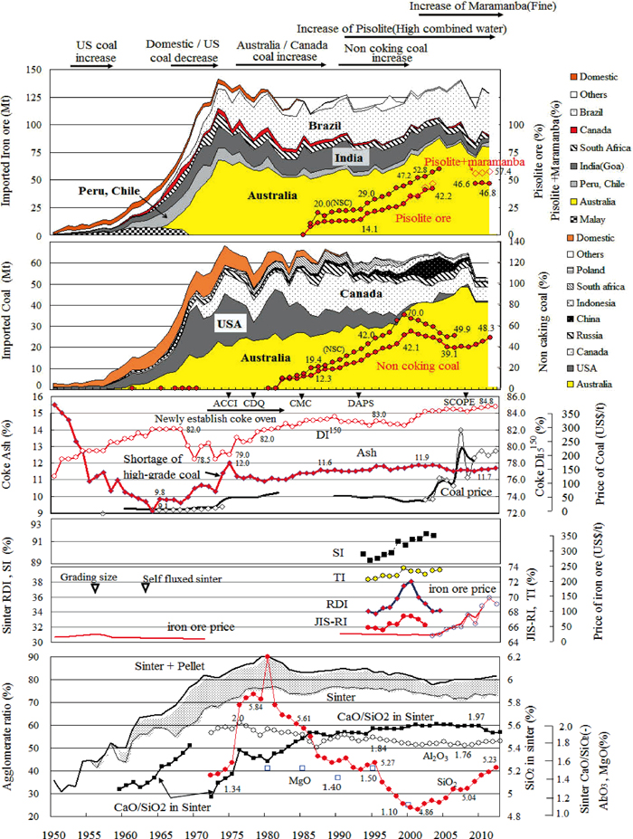
Because imports of burden materials from China ended after the war, Japan imported iron ore primarily from the Philippines and Malay Peninsula, while depending on America, Canada, and India to make up the remainder, and imported a great part of caking coal from America.73) Although imports of these burden materials increased as production capacity expanded, construction of dedicated iron ore carriers to reduce transport costs81) made it possible to diversify supply sources, and imports from distant countries such as Peru and Chile in South America began to increase. After December 1960, when the Australian government conditionally suspended the prohibition on exports of iron ore,81) imports of iron ore from Australia increased rapidly (Fig. 562,76,79,83,86,105)). Long-term contracts of 10 to 15 years supported stable procurement of the high quality iron ore needed for rapid growth. Coal was imported not only from America, but also from Canada, Australia, and Russia (former USSR) (Fig. 5). In 1963, imported coal accounted for 55.3% of Japan’s total coal, and American coal decreased to 54.6%83) of imported coal. In the 1960s, imported ore prices and coal prices were maintained at about US$13/t and about US$16/t (Australian coal US$13.5/t), respectively, by the above-mentioned measures.
There was a remarkable acceleration of technical innovation, including improvements to self-fluxed sinter74,76) and coke quality, along with advances in combined blasting technologies such as moisture controlled blast, dehumidified blast,75) oxygen enrichment, and heavy oil and coke oven gas (COG) injection, and the construction of operation control systems.86) Heavy oil injection, which was tested at Nippon Kokan’s Kawasaki No. 3 blast furnace in 1961, was immediately developed as practical equipment, and was widely adopted due to the simple injection equipment and large coke rate reduction effect.70)
Japan’s crude steel production surpassed that of the United Kingdom in 1960, and Japan became the world’s fourth largest steel producer. Japan also overtook West Germany in 1963 and produced 39.78 million tons in 1964, ranking number three in the world.79) RAR fell to 518 kg/thm in 1970, although this included an average heavy oil injection rate of 45 kg/thm. 1970 was a momentous year in the business history of the steel industry, as Yawata Iron & Steel and Fuji Iron & Steel merged to form Nippon Steel Corporation.
During 1970’s, large blast furnaces were built on reclaimed land in coastal areas. In 1971, the 4000 m3 class Fukuyama No. 4 blast furnace at Nippon Kokan and in 1976, the 5000 m3 class Kashima No. 3 blast furnace at Sumitomo Metal and Oita No. 2 blast furnace at Nippon Steel were constructed. As blast furnace size increased, most of the world’s new technologies were introduced in a short time,70) including high pressure process equipment, stave cooler systems, movable armor, bell-less charging systems, large hot stoves, hydraulic mud guns, and computer control systems.
In 1973, 60 blast furnaces were in operation, all of which used heavy oil injection, and 70% had also been converted to high pressure blast furnaces. Crude steel production reached 16% of the world’s total production, at 120 million t/y. Among operational indexes, productivity reached 2.04 t/d/m3 and RAR improved to 494 kg/thm (including heavy oil: 56 kg/thm), ranking first in the world. Around 1970, dissection analyses106) of blast furnaces in each company were conducted in order to obtain an understanding of the behavior inside of blast furnaces, which was regarded as a “black box”.
Throughout the postwar reconstruction period and the period of high economic growth from 1955 to 1981, the Experimental Blast Furnace107) at the University of Tokyo was operated as a cooperative industry-academia project in the field of ironmaking. This facility played a key role in the development of ironmaking technologies, the training of university graduate students through hands-on exercises, and the development of new blast furnace technologies such as hearth-blowing refining and reducing agent (oil) injection.
2.4. Energy Conversion in Response to the Oil Crises, Expanded Use of Low Cost Resources: 1973–2000
By the early 1970s, the Japanese steel industry had made great strides in acquiring the world’s top level technological capabilities while also steadily expanding production. However, the 1st Oil Crisis in 1973 and the 2nd Oil Crisis at the end of 1978 signaled the end of the period of high economic growth and a change to a period of stable growth.
The number of operating blast furnaces dropped from 62 in 1970 to 43 in 1978. In consequence, crude steel production transitioned from a peak of 120 million tons/year in 1973 to a level of around 100 million tons/year (Fig. 4).
Following the 1st Oil Crisis, steel works prioritized energy saving measures86) by adopting such technologies as top gas pressure recovery turbines (TRT), which utilize the pressure of blast furnace top gas to generate electric power, waste heat recovery systems for the sinter machine and the hot stove of blast furnace , and coke dry quenching systems (CDQ). These measures yielded a 10% decrease in energy unit consumption over the six years to 1979, while the proportional component of petroleum as a reducing agent dropped from 21.3% to 14.2%.
During the 1970s, shortages of high quality coal (caking coal) drove a jump in the prices of imported coal for coke from US$25/t (Australian coal: US$19.8/t) in 1973 to US$45/t (Australian coal: US$26/t) in 1974, US$57/t in 1975, and US$74/t in 1982. In blast furnace operation, studies pursued reduction of RAR to the minimum possible limit (see section 4.1),1,2,3) resulting in operation with productivity of 1.93 t/d/m3 and a national average RAR of 461.6 kg/thm (including heavy oil: 38.6 kg/thm) in 1979 (Fig. 4).86)
However, rocketing oil prices during the 2nd Oil Crisis far exceeded the rise in the price of caking coal. In response, by the end of 1981, 42 of the total of 43 operating blast furnaces had been changed over to oil-less operation. Until then, companies had competed over reduction of RAR as a major technology common to the entire industry, but after the 2nd Oil Crisis, RAR was set to a relatively high value in order to increase generation of byproduct fuel gases (blast furnace gas and coke oven gas), and thereby reduce consumption of oil for power and heating furnaces in the steel works. This also blazed the trail for conversion of the entire steel works to oil-less operation.
Thus, RAR began to rise, with 1979 as the turning point, and exceeded 500 kg/thm from 1985 on. Other key issues in this period of economic retrenchment included the use of low-grade coal, non- or slightly-caking coal, and other possible alternatives to expensive coke as a reducing agent in blast furnaces. The use of formed coal blends, dry coal/pre-heated coal charging processes, and others in coke ovens led to the use of non- or slightly-caking coal and semi-soft coal.105) These technological developments accelerated the break from dependence on heavy caking coal, and brought about a conversion and strengthening of coal purchasing strategies. Following the introduction of pulverized coal injection (PCI) technology in 1981 at Nippon Steel Oita No. 1 blast furnace (inner volume: 4884 m3),28,29) 16 blast furnaces nationwide, or 50% of the total, had switched to PCI operation by 1986.
However, in 1985, the Japan’s steel industry entered a great period of transition as a result of the rapid appreciation of the yen from 240 yen/US$ to around 150 yen/US$ brought about by the Plaza Accord of that year (Fig. 4). The appreciation of the yen put exporting industries in a particularly difficult position, inspiring the steel industry to study measures for devising corporate structures that would be capable of securing profitability even at annual crude steel production of 90 million tons/y. In implementing these measures, Nippon Steel shut down the blast furnaces at its Kamaishi Works in 1989, at Sakai Works in 1990, and at Hirohata Works in 1993, as well as one blast furnace each at Yawata Works and Muroran Works. Although 40 blast furnaces were in operation in Japan in 1985, this number was reduced to 31 by 1994. During this period, crude steel production temporarily rebounded to 110 million t/y in 1990, but due to the subsequent collapse of Japan’s so-called “bubble economy” and the further appreciation of the yen in 1994, production levels remained low throughout the 90 s. To reduce hot metal costs, companies implemented a variety of streamlining measures such as facilities consolidation, priority production systems, and restructuring by workforce reductions. The index of workers per blast furnace fell rapidly from 1.000 in 1985 to 0.396 by 2000, indicating a vast improvement in productivity per person.4)
Iron ore and coal, which make up a large portion of hot metal iron costs, were also subjected to stringent cost reductions. Both imports of iron ore from Australia,87) whose transport distance is shorter than Brazil’s, and use of cheap pisolitic ore were expanded (see Chapter 3). From 1990 to 2003, the price of ore remained around US$25/t, and due to the expanded use of non- or slightly-caking coal,87) the price of imported coal, which had been US$74/t in 1982, dropped to US$44/t in 2000 (Fig. 5).
High pulverized coal (PC) rate operation was used at 25 blast furnaces in 1996 and had spread to all 31 blast furnaces in Japan by 1998 (Fig. 4), with the average injection rate reaching 130 kg/thm (CR: 370 kg/thm). In pursuit of further increases in the PC rate at steel works with an insufficient coke supply capacities, high PC rate operation at over 250 kg/thm was tested at Kobe Steel and Nippon Kokan (NKK).
National projects during this period aimed at strengthening resource flexibility, realizing high productivity, and reducing environmental impacts. Projects included the development of formed coke manufacturing technology108) from FY1978 to 1986 and the development of a direct iron ore smelting reduction process (DIOS)109) from FY1988 to 1995. Incorporating the aims of expanding the types of coal and reducing environmental impacts, formed coke is made by briquetting and then carbonizing coal in a vertical carbonization furnace instead of the conventional chamber oven, using non-caking coal as the main raw material. DIOS is also a manufacturing process that uses non-caking coal (see section 6.1).
2.5. Transition to Larger Blast Furnaces, Streamlining, Environmental Recycling, and CO2 Reduction (Latter Half of 1990s to Present)
The latter half of the 1990s was characterized by a recurrence of the economic downturn caused by the drastic rise in the yen exchange rate in the 1980s, and the establishment of voluntary action plans in response to the Kyoto Protocol spurred a flurry of investigations into energy-saving initiatives and recycling technologies. Development of a number of recycling technologies went forward, including processing of waste plastics in blast furnaces44) and coke ovens,45) dezincification of dust with high Zn contents using rotary hearth furnaces (RHF)46) and use of the generated reduced iron in the blast furnace, and dust and scrap processing.50,51)
From 2000 onward, the trend in blast furnace improvements was toward expansion of furnace capacity, and by 2013, 13 of the 27 blast furnaces in Japan had been converted to 5000 m3 class large blast furnaces. Blast furnace service life was extended through the development of carbon blocks,53,55) introduction of Cu staves,53,56) and similar activities. Coke oven service life was extended by measures including installation of coke oven chamber furnace wall diagnostic and repair equipement.110)
Beginning in 2002, the Japanese steel industry returned to life after a long slump, supported by considerably expanded production in response to the strong growth of the Chinese economy. The average iron productivity of blast furnaces surpassed 2.0 t/d/m3, and iron production exceeded 82–86 million tons/year, while crude steel production exceeded 110 million tons/year. In 2007, iron productivity was 2.08 t/d/m3 and crude steel production was 120 million tons, the highest production values since 1973. In contrast to 1973, when 60 blast furnaces were in operation (iron productivity: 2.04 t/d/m3, RAR: 494 kg/thm, heavy oil rate: 60 kg/thm), in 2007, 30 blast furnaces were in operation (iron productivity: 2.08 t/d/m3, RAR: 497 kg/thm (including PC: 123.6 kg/thm)). These figures represent the fruition of a host of general improvements, including the expansion of blast furnaces, burden material quality improvements, PCI, facility improvement, computer control, and others. Due to the economic downturn caused by the bankruptcy of Lehman Brothers in September of 2008, operation took a turn from high production to production cutbacks, and then started trending toward recovery. Crude steel production in 2011 and 2012 was down 10% from 2007, falling to the 107 million ton range. In 2012, 26 blast furnaces were in operation at iron productivity of 1.87 t/d/m3 and a RAR of 503 kg/thm (including PC: 161 kg/thm).
In 2002, Japan began importing Marra Mamba ore, a new brand of Australian ore with a large amount of fines, and more recently, high phosphorus Brockman ore. However, since 2004, sharply increasing Chinese imports have caused iron ore and coal prices to soar, and as a result, in 2008, iron ore was priced at a high US$90/t, and from April to June of 2011, at an even higher US$171/t. Similarly, coal was also priced at a high US$230/t in 2008 (Australian coal US$300/t). Since then, prices have remained in the high range. In the future, it is considered likely that resource prices will be governed by trends in Chinese demand.
National projects and related basic research were implemented during this period with the aims of strengthening resources flexibility, realizing high productivity, and reducing environmental impacts. These included SCOPE21 (Super Coke Oven for Productivity and Environmental enhancement toward the 21st century; 1994–2003),111,112) Science and Technology of Innovative Ironmaking for Aiming at Energy Half Consumption (1999–2004), Leading Research into Innovative Ironmaking Processes (2006–2008), and Development of Innovative Ironmaking Process for Strengthening Resource Response Capabilities (2009–2012) (see section 5.1).
SCOPE21 is a technology featuring strengthened coal preprocessing and high speed carbonization, and was adopted in new coke ovens at Nippon Steel Oita Works in 2008 and Nippon Steel Nagoya Works in 2013. As technologies for reduced CO2 emissions and realizing low RAR operation, technologies for thermal reserve zone temperature control and chemical equilibrium control were developed113,115) (see section 5.1), and at JFE East Japan Works (Keihin), injection of natural gas was adopted in the blast furnace and sintering process.52,116) A two-stage reduction system117) combining partially-reduced iron ore manufacturing in natural gas producing countries and use of the product ore in Japanese blast furnaces was proposed as a globally-oriented CO2 reduction technology that also encompasses use of inferior quality resources. Recently, a feasibility study on nuclear-hydrogen reduction process of iron ore using Very High Temperature Gas-cooled Reactor (VHTR)118) has been preliminarily performed by the Iron and Steel Institute of Japan’s Green Energy Study Group. Another national project, Research on Innovative Ironmaking Process Technologies (see section 5.2.1), was also carried out from 2008 to 2013.
3. Evolution of Quality Improvement in Blast Furnace Burden Materials
The quality of blast furnace burden materials must be pursued in accordance with the operating conditions (low RAR operation, low Si content, high productivity, high PC rate, etc.) targeted by the blast furnace, based on an understanding of the properties of the burden materials being used. Along with the establishment of a standard quality evaluation method, initiatives were carried out to improve quality while using low cost burden materials.
3.1. Improvement of Sinter Quality
Burden material quality has a major effect on blast furnace stability and reaction efficiency. The superiority of sinter has been known since prewar days.70,101) In 1958, Fuji Iron and Steel Muroran Works operated using 100% sinter (FeO: 19.9%) and Sumitomo Metal Industries operated using 100% self-fluxed sinter74) (FeO: 10.62%, CaO/SiO2: 1.23). Because the use of self-fluxed sinter decreased the coke rate and contributed to an increase in productivity, all companies switched over to high basicity sinter operation, in which 100% of the limestone to be used in ironmaking is blended in the sinter. As a result, limestone charging to the blast furnace has mostly been eliminated (Fig. 4).
Evaluation methods for sinter quality began for the purpose of supporting the development of new mines, long-term purchasing contracts, and increases in sinter blend ratios. The 54th Committee on Ironmaking established test methods for the shatter index (SI) and reducibility (JIS-RI, 1966).119) As the target for sinter quality at that time, the ideal sinter was considered to have highly reducible minerals in low temperature sintering and high porosity, enabling good gas diffusion. During the 1960s, deterioration of permeability and unstable blast furnace operation due to the formation of a low temperature thermal reserve zone120) in the range of 500–700°C in the blast furnace shaft became issues.77) Degradation of sinter during reduction was reported at Yawata Works and Sumitomo Metal Industries,121,122) and it was found that this degradation increases drastically in the temperature range of 500–600°C.121,122,123) Starting with Fuji Iron & Steel Hirohata Works, all companies initiated sinter reduction degradation testing,121,124,125) and in 1974, the 44th Ironmaking Committee of the Iron and Steel Institute of Japan established a RDI standard procedure as an index for sinter reduction degradation. Countermeasures for improving RDI have been developed, including increases in sinter basicity (CaO/SiO2),121) gangue amount,121,126) and FeO content (manufacture of magnetite sinter)121,127) and addition of chlorides.128)
In 1977, the Technical Research Institute at Nippon Steel Muroran Works began measurement of high temperature characteristics using testing equipment capable of continuous measurement from softening to molten dripping.129) Imaging the phenomena from ore softening to melting and dripping, which are an important part of blast furnace operation, the melting start temperature (TS), dripping start temperature (Td), maximum pressure value, 50% shrinkage ratio, S value, and other indexes were presented.
From another perspective, Nippon Steel developed a blast furnace inner reaction simulator (BIS) to enable precise investigation of the reactions inside the blast furnace.113,130) The BIS was used to reveal the reducing behavior inside the blast furnace and to investigate the effects of various types of burden materials.
A number of technologies were developed with the aim of improving sinter quality and increasing productivity,4) including increased JIS-RI, refining of the quasi-particle structure through low SiO2-type HPS (hybrid pelletized sinter)5) sinter ore manufacture, which achieves a reduction in coke breeze consumption and strengthening of agglomeration,6) manufacture of low SiO2 sinter by reducing the amount of fluxes131,132,133) (in 2001, the sinter SiO2 component was 4.86%), enhancement of the functionality of the sinter machine supply drum feeder (intensified sifting feeder, ISF),8) air classification9) and magnetic segregator charging,134) selective pelletization alumina containment technology (detoxification),11) and the stand support sinter method.12) As a result, it became possible to increase the ratio of pisolitic ore135) while also improving sinter strength, and in 2000, 36.4% of all imported ore (53% in the case of Nippon Steel)4) was pisolitic ore (Fig. 5). In 2002, companies began importing Marra Mamba ore, which has a high fines content, and all companies focused their efforts on agglomeration technologies. These included techniques for using organic binders to improve the pelletization of fine raw materials, SPEx II facilities using hard mini-pellet manufacturing,91) and the RF-MEBIOS process.136)
3.2. Pellet Manufacturing and Blast Furnace Operation Technology
Ironmaking burden material manufacturing has developed based on ore sizing and the use of self-fluxed sinter, and also considered pellets as a future burden material.77) In research and industrialization of pellets, although Japan lagged behind Europe and the United States in industrialization, this was achieved within a few short years by Hitachi Metals, Ltd., Teikoku Iron and Steel Works, and Kawasaki Steel during the 1950s. In 1953, the first pellet plant in Japan was built at Kawasaki Steel Chiba Works (now JFE Steel East Japan Works (Chiba)) using an original negative pressure shaft furnace, and 2.50 million tons/year Allis-Chalmers pelletizing plants, the largest class in the world, were built at Kobe Steel Kakogawa Works in 1970 and at Nippon Steel Hirohata Works in 1973.
Testing of the use of imported pellets in blast furnaces began at Fuji Iron & Steel and Nippon Kokan in 1963. All companies carried out research into improving pellet quality, and Kobe Steel developed self-fluxed pellets in 1967. Compared to sinter, pellets have the disadvantages of reduction stagnation at high temperature and of rolling easily to the center of the blast furnace during charging because of their smaller angle of repose. To overcome these problems, Kobe Steel developed dolomite-fluxed pellets with improved high temperature properties and a center coke charging process that inhibits flowing into the furnace center.137)
In high pellet rate operation, which is used by Kobe Steel,138,139) it is necessary to control the ratio of low basicity pellets at the furnace periphery due to the softening and melting characteristics of the pellets. Therefore, the company developed a pellet time-series discharge control process, and based on this knowledge, Kobe No. 3 blast furnace (inner volume 1845 m3) switched to high pellet ratio operation in 2001.140)
For operations that use large amounts of pellets, a new concept of operation using pellets was presented, in which the center gas flow can be secured by applying a center coke charging process, and the high temperature reducibility of the pellets is improved by injecting large amounts of pulverized coal to create a low heat flow ratio in the blast furnace peripheral area. Figure 6 shows the recent ferrous burden composition in typical blast furnaces.140) It was possible to shift to high pellets ratio operation at a lump ore ratio of 25% at Kobe No. 3 blast furnace with bell-less center coke charging method.
3.3. Improvement of Coke Quality
Following the introduction of modern iron and steel making technologies, efforts to improve permeability and stabilize blast furnace operation have been directed toward increasing the strength of coke as the next subject. Cold strength after carbonization (drum strength DI) and strength after hot reaction (CSR:141) Coke Strength after-CO2 Reaction) were specified as important indexes for evaluating coke quality, and technologies for manufacturing high strength coke by blending a wide range of different brands were studied. The JIS reactivity index, which expresses reactivity at low temperature (950°C) and the Coke Reactivity Index (CRI), which expresses reactivity at high temperature (1100°C), were used for reactivity.
The use of cheap non- or slightly-caking coal began in the 1980s, and coke strength improvement and expanded use of non- or slightly-caking coal went forward. The briquette blending process for agglomeration of non- or slightly-caking coal and coal moisture control (CMC)14) for improving bulk density were deployed widely, and the dry-cleaned and agglomerated pre-compaction system (DAPS)15) was developed as a technology for drying and selective pelletization of coal fines (Fig. 8). The moisture content of blended coal decreased from the 8% range in 1990 to 4.7% in 2002, and the percentage of non- or slightly-caking coal ratio had expanded to 47% by 2000 (53% blend while maintaining coke strength at Nippon Steel in 20024)).
In the 2000s, larger blast furnace inner volumes of the 5000 m3 class became the main stream, and enhanced coke strength was needed to maintain high production. For a short time, non- or slightly-caking coal use decreased from the 50% range to the 40% range, but recently, production of high strength coke of about DI15150 85 accounts for approximately 50% of the total.
4. Progress and Improvements in Blast Furnace Operation and Facilities, Challenging the Limits of Operation
The ironmaking technologies which were introduced during the period of rapid economic growth evolved into original Japanese technologies with globally-recognized blast furnace operation performance. At the same time, the Japanese steel industry also carried out research and development that included theoretical analysis and modelling. This section summarizes typical technologies and mentions the system development and facility technologies that have supported them.
4.1. Challenges in Low Coke Rate Operation
4.1.1. Low Reducing Agent Rate Technology
Before the Oil Crises, the challenges in low coke rate operation focused on low RAR operation and then shifted to low coke rate operation with a high PC rate. Technologies previously proposed or implemented as means of realizing low RAR operation included improvement of the reducibility of the agglomerated ore and techniques for ore layer control (burden distribution control), such as mixed charging targeting improvement of high temperature characteristics, improvement of reducibility by increasing H2, and reduction equilibrium control by using highly reactive carbon material. Other approaches included heat balance improvement, increasing the blast temperature, reducing the blast moisture content, using high calorific injectants, reducing molten iron Si, reducing the slag rate, decreasing the hot metal temperature, burden distribution control to prevent furnace fluctuations, improving the gas utilization ratio in the radial direction, reducing heat loss, and using metallic iron (Fig. 7).

Japan started on the path to lower RAR operation in the 1950s with ore sizing and the use of self-fluxed sinter. In the 1960s, all companies adopted low RAR operation by various approaches that included increasing the sinter and pellet ratio, improving the quality of sinter (self- fluxed sinter, high basicity sinter), heavy oil injection, blast moisture control (including dehumidification), raising the blast temperature, oxygen enrichment, burden distribution control, increasing the top gas pressure and furnace inner volume, and use of high quality raw materials (low ash coke, low FeO sinter) (Fig. 8).
In November of 1980, Nippon Steel Kimitsu No. 4 blast furnace was operated at a reducing agent rate of 406 kg/thm1) under operating conditions of a blast temperature of 1336°C, moisture content of 4.6 g/Nm3, and heavy oil rate of 37 kg/thm, and in November 1981, Nippon Kokan Fukuyama (now part of JFE West Japan Works) No. 3 blast furnace (inner volume: 3220 m3) established a world record for low RAR of 396 kg/thm3 3) under operating conditions of a blast temperature of 1350°C, moisture content of 5.6 g/Nm3, and tar rate of 40 kg/thm. Thus, it can be said that the Japanese steel industry achieved the limit of low RAR operation of blast furnaces. Figure 9 shows illustrations of the inner states of two blast furnaces in low RAR operation.3)

Low RAR operation with PCI was adopted at Nippon Steel Oita No. 2 blast furnace (inner volume: 5245 m3) in operation at a RAR of 455 kg/thm (PCR: 98 kg/thm, CR: 257 kg/thm) in 1994 and at Nippon Steel Nagoya No. 3 blast furnace (inner volume: 4300 m3) in operation at 488 kg/thm (PCR: 189 kg/thm, CR: 299 kg/thm) in 2011.91) The right side of Fig. 9 is an image of the inside of Oita No. 2 blast furnace during low RAR operation, which was obtained from measurements with a vertical probe and belly probe, and shows how the level of the cohesive zone has decreased to its extreme limit.30)
As alternative reducing agents of various phases, gas (natural gas: NG), solid (PC), and liquid (oil) have different combustibilities and calorific values. Figure 10 shows the low RAR operation records for various countries by the type of injected fuel. At POSCO in the neighboring country of Korea, Pohang No. 3 blast furnace (inner volume: 3795 m3) operated at a RAR of 493 kg/thm (PCR: 222 kg/thm, coke rate: 271 kg/thm) in 2002. The operational data and burden quality in typical operations are shown in Table 2.90)
Table 2. Blast furnace operation data with low RAR and high PC operation.
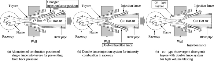
High pulverized coal injection rate (PCR) technology has been the subject of study with the aims of reducing the load on coke ovens, coping with poor quality resources, and reducing costs. The advantage of PCI is that it is an economical process allowing the direct use of coal in the blast furnace without agglomeration. However, several engineering issues arise because PC is a solid material, for example, stable conveyance of large amounts of pulverized coal to a large scale, high pressure, high temperature blast furnace, equal distribution of PC among multiple tuyeres, and combustibility in the raceway.42,142) Various studies143) have been carried out on injection lance techniques (Fig. 11), the injection position, the types of coal used in PCI, and the behavior of fines generation inside the furnace.
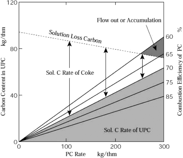
Unburnt pulverized coal (unburnt char) produced in the raceway and coke fines are consumed inside the furnace by the carbon solution loss reaction (Fig. 12).43) According to an analysis by a solid-gas two-phase flow model of a packed bed, large amounts of unburnt char and coke fines accumulate at the surface of the deadman, and particularly at the lowest part of the cohesive zone, where the direction of the gas flow changes steeply, and in the case of a W-shaped cohesive zone, this intensifies the peripheral gas flow (Fig. 13). The countermeasures for this gas flow change are not only improvement of the injection lance, but also burden distribution control technologies such as center coke charging for center flow operation,38) use of high strength coke, and formation of an inverted V-shaped cohesive zone.
Furthermore, because the ore-to-coke ratio increases in high PC rate operation, the high temperature properties of sinter are a focus of study. Methods such as improving sinter reducibility (see section 3.1), thinning the ore layer (lowering the coke base), using large amounts of nut coke and highly reactive carbonaceous materials, and others have been considered to improve the reducibility of the ore layer and the permeability of the cohesive zone.4)
High PC rate techniques have been developed, mainly at steel works with insufficient coke supply capacities. In 1990, Kobe Steel Kakogawa No. 2 blast furnace (inner volume 3850 m3) broke the coke rate barrier of 300 kg/thm for the first time by combined injection of pulverized coal and heavy oil, and established a record of operation at 298 kg/thm (PCR: 123 kg/thm, heavy oil rate: 62 kg/thm). As works that broke the limits of high PC rate operation, operational testing at over 250 kg/thm was conducted at Kobe Steel Kakogawa No. 1 blast furnace (inner volume: 4550 m3) and NKK Fukuyama No. 3 blast furnace (inner volume: 3223 m3) in 1998. Kakogawa No. 1 blast furnace achieved a PCR of 254.4 kg/thm and CR of 291 kg/thm (total RAR: 545.4 kg/thm),32) and Fukuyama No. 3 blast furnace achieved a PCR of 265.5 kg/thm and CR of 289 kg/thm (total RAR: 554.5 kg/thm)33) (Table 2, Fig. 10). On the other hand, the coke-to-coal replacement ratio decreased in the process of increasing the PCR from 200 kg/thm to 250 kg/thm. The likely cause of this was discharge of coke fines from the top of the furnace.
In China and Korea, use of high quality burden materials and optimization of blast conditions such as high oxygen enrichment were adopted with the intention of reducing the coke rate in high PC rate operation.
In the past, various aspects of high PC rate operation were studied, such as the effects of burden material quality, control of the cohesive zone through center flow operation, the function of the raceway as a combustion site, and the function of the cohesive zone as a gas reaction site for unburnt char.142,143)
To address the above-mentioned problem of the decreased coke-to-coal replacement ratio in high PC rate operation, further development of high PC rate technologies to break the limits on low coke rate operation is expected, together with an academic approach to understanding the behavior in the blast furnace.
4.2. Burden Distribution Control Technology
The purpose of burden distribution control is to maximize reducing efficiency while maintaining both burden descent and gas permeability by controlling the buildup of the layers of the burden at the top of the blast furnace. The importance of burden distribution control has long been recognized. A book on the theory of blast furnace ironmaking144) in the 1950s stated that, while obtaining a gas flow in a narrow area in the vicinity of the furnace wall, it is necessary to strengthen the gas flow in the central area. Based on this concept, burden distribution control technologies have developed in sophistication with the conversion from bell to bell-less charging devices following increases in the top gas pressure and the size of blast furnaces, and elucidation of in-furnace behavior by dissection analyses of blast furnaces, leading to the proposal of a concept of cohesive zone shape control.
4.2.1. Bell-type Charging Systems
Single bell-type charging systems for furnace top gas shielding (recovery) and burden charging are used with normal pressure blast furnaces, 2-bell, 1-valve systems have been generally introduced at high pressure blast furnaces, and bell-MA charging systems equipped with movable armor (MA) that controls the falling trajectory of the burden have been developed and are used with large blast furnaces (Fig. 14).145)
In small bell blast furnaces without MA, the falling position is adjusted by changing the stock level, and the radial distribution of the ore-to-coke ratio is controlled by changing the amount of each batch and the charging sequence. For example, the radial gas flow distribution has been controlled by selecting the charging mode as follows:144)
(1) OOO↓CCCC↓: Separate charging, layer charging
(2) OOCC↓OCC↓: Ore first feeding and separate charging, mixed charging
In large bell blast furnaces, burden materials falling from the large bell strike against the movable armor, changing the falling trajectory in the radial direction and the charging location inside the furnace. Many models have been developed147,148,149) in order to consider fundamental phenomena related to layer formation, such as the falling trajectory from the large bell, fluidization of coke during ore charging, formation of mixed layers, and the decrease of the angle of inclination caused by burden descent and gas flow.146) These models are used to obtain operational guidance predicting permeability distribution, which is determined by such factors as the ore-to-coke ratio and particle diameter.
4.2.2. Bell-less Charging Systems
Bell-less charging systems enable control of the burden material falling position by changing the angle of the rotating chute. This type of system features greater flexibility in the charging position compared to bell-MA systems. This technology was first introduced in 1973 at Nippon Steel Muroran No. 1 blast furnace (inner volume: 1245 m3). Because reduced facility weight and lower construction costs can also be expected, it was also introduced in 1977 at Kawasaki Steel Chiba No. 6 blast furnace (4500 m3), which is a representative large blast furnace.145) In 1978, five of 61 blast furnaces in Japan used bell-less charging systems, and in 2013, this figure was 20 blast furnaces out of 27. The first bell-less charging systems consisted of two parallel bunkers at the blast furnace top. As the problem of non-uniformity in the circumferential direction around the furnace top became apparent, a 2-stage center feed vertical bunker system was introduced. To ease the strain of non-uniformity in the circumferential direction, a 3-parallel bunker system capable of dividing burden materials of different sizes and qualities into several batches for charging was developed150) and deployed to the Chiba No. 6 blast furnace and other blast furnaces (Fig. 15). To control the horizontal falling speed and the falling width of the burden materials from the rotating chute, a new type of chute, which is equipped with a repulsion plate at the chute end, was developed and put into practical use.151,152)

All companies developed bell-less burden distribution models in order to take advantage of the high flexibility of bell-less systems in control of burden distribution.153,154) Using one such model, Kajiwara et al.155) showed that flat charging, which bell-MA charging systems cannot achieve, is possible with bell-less blast furnaces.
4.2.3. New Developments in Burden Distribution Control
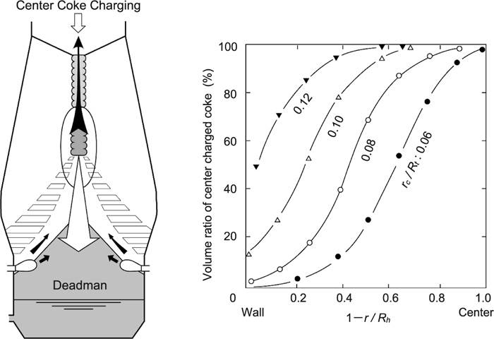
Technical developments are underway for radial distribution control of the gas flow in the blast furnace shaft and control of the shape of the cohesive zone, center coke charging to control the structure of the deadman, and heavy coke mixed charging to improve permeability in the cohesive zone.
As shown in Fig. 16, cold experiments on deadman renewal demonstrated that the whole volume of the deadman was renewed by coke charged within a dimensionless radius of 0.12.38) Based on this, an innovative concept of the basic principle of furnace deadman control proposed, and this concept was embodied in a practical center coke charging system at Kobe Steel Kakogawa No. 2 blast furnace (inner volume: 3850 m3).
Although the concept of using mixed charging as a means of significantly improving the permeability of the cohesive zone was proposed and realized in practical use with nut coke mixed charging in the 1970s,156) issues such as re-segregation in the blast furnace remained in the case of high mixed charging rates at large blast furnaces. By developing hardware in the form of the 3-parallel bunker bell-less top and the concept of reverse tilting charging, JFE Steel realized a technology that enables high mixed charging rates by simultaneously charging all sizes from nut to lump coke and ore from two top bunkers at Chiba No. 6 blast furnace.157)
Development of new burden distribution control technologies is expected in the future, including technology enabling arbitrary placement of various burden materials, such as carbon-containing agglomerates, ferrocoke, ore classified by size, and coke for forming the deadman, the optimum packed structures inside the blast furnace that can also provide permeability in low coke rate operation, and hardware and software (control) technologies for realizing those structures.
4.3. Low Si Operation Technology
The Committee on Reaction within Blast Furnace (1977–1982),158) a study group of the Iron and Steel Institute of Japan, conducted thermodynamic research and research on reaction kinetics based on a blast furnace dissection study and data from test blast furnaces. The mechanism of the Si transfer reaction inside the blast furnace was also studied by analyzing slag samples collected from the boundaries of actual furnace raceways and the oxygen partial pressure with the objective of gathering data during operation.19)
Previous studies16,17,18,19,20,21,22,23) on the mechanism of Si transfer to molten iron suggested that the reaction proceeds by the following three steps (Fig. 17).
(1) SiO gas generation from coke ash and slag
SiO2(s,l) + C(s) = SiO(g) + CO(g)
(2) Si transfer to molten iron from SiO(g)24)
SiO(g) + C = Si + CO(g)
(3) Desiliconization or siliconization in molten iron by FeO or MnO in slag19)
2(FeO) + Si = 2Fe + SiO2, 2(MnO) + Si = 2Mn + SiO2
Various measures for controlling each reaction in the above three steps have been discussed with the aim of achieving low Si operation. The following methods have been proposed for the respective reaction steps: Step (1) Higher CO partial pressure (higher pressure), lower coke ash content, higher ore basicity, lower flame temperature (lower blast temperature), and injection of ore fines and flux from the tuyeres; Step (2) Higher CO partial pressure (higher pressure), higher heat flow ratio to decrease the hot metal temperature and reduce RAR, use of high basicity sinter in blends, and high metal dripping temperature with addition of MgO to lower the lower boundary of the cohesive zone; and Step (3) Lower hot metal temperature, lower activity of SiO2 in slag (basicity increase) and early tapping (dry hearth) to reduce the siliconization reaction, and injection of ore fines from the tureyes.4)
Low Si operation at NKK22) was oriented toward a lower flame temperature in order to suppress SiO gas generation, but had the disadvantage of high RAR. On the other hand, low Si operation at Nippon Steel19) was oriented toward smaller siliconizing areas by lowering the cohesive zone while lowering RAR,17,159) which also had the effect of increasing the oxygen partial pressure in front of the tuyeres by high FeO slag dripping to suppress the production of SiO gas and facilitate the slag-metal desiliconization reaction.
The above Si reduction measures by NKK and Nippon Steel achieved low Si operation of molten iron Si in the range of 0.1 to 0.2% in 1984 and 1988, respectively.
In October 1997, low Si operation was conducted at all blast furnaces at NKK Fukuyama Works, including PCI blast furnaces, by low hot metal temperature operation, following the development of a system that enabled direct measurement of the molten iron temperature immediately after discharge from the tap hole by means of an optical fiber (FIMPIT). Extremely low Si operation was achieved at all three blast furnaces, which had a monthly average Si of 0.18% (annual average: 0.22%) (Fig. 18).22)
While kinetic analysis was carried out to improve the accuracy of molten iron Si forecasts, the Si content in molten iron has also been used as an operational control index because it represents the state of the furnace heat level.
Tsuchiya et al.18) obtained the relationship between the molten iron Si content and the shape of the cohesive zone in the blast furnace, while Baba et al.159) used the cohesive zone level observed by the belly probe at Nippon Steel Oita No. 2 blast furnace to correlate the cohesive zone level with the Si content. Kushima et al.19) focused on the fact that the final slag FeO concentration in stably operating blast furnaces is about 0.2% and proposed a control index for determining the operational allowance from the difference between the actual molten iron Si content and the equilibrium content of FeO = 0.2%.
4.4. Multiple Injection Technology as Enhancement of Blast Furnaces Functions
Multiple injection technologies, in which fines are injected into the tuyeres for low Si operation and direct use of fine iron ore, have been studied.25,26) In the initial stage, a small amount of fine ore (50 kg/thm) was studied for desiliconization in the blast furnace. From 1981 to 1982, injection tests of sinter fines with an average particle diameter range of 2–3 mm were conducted using four tuyeres of Nippon Steel Hirohata No. 3 blast furnace (inner volume: 1690 m3, 23 tuyeres).25) According to RI tracer measurements, the Si content during injection of sinter fines was lower by 0.14% than during the base period. It was considered that the increase of the oxygen partial pressure PO2 at the boundary of the raceway suppresses SiO generation, and FeO slag contributes to desiliconization.19) Combined injection of ore fines and PC and injection of fluxes (quicklime, burnt dolomite, magnesia clinker, etc.) were also discussed, and Kawasaki Steel installed a sideways tuyere probe160) at Chiba No. 5 blast furnace (inner volume: 2584 m3) and investigated the raceway shape and the effects of injection of ore fines and fluxes on Si content.
As a further development of the multiple injection technology described above, a technology for injection of large amounts of fine ore27,161) was proposed. This is a next-generation multiple injection technology and is expected to overcome a number of issues, including (1) blast furnace operational flexibility, (2) wider choice of materials (use of hard-to-sinter fines), (3) permeability during high PC rate operation, and (4) flame temperature and heat flow ratio control during high oxygen enrichment.27) Nippon Steel built a test blast furnace (hot model) to accommodate these development activities, studied the limits of the ore fines injection rate and the merits of the technologies, and demonstrated that the limit of ore fines injection is 100 kg/thm when combined with PCI.27) Following coke packed hot bed experiments, Sumitomo Metal Industries carried out single tuyere testing of this technology, which it named “Ultra multiple combined injection,” at Wakayama No. 3 blast furnace.161) Similar results were obtained, in that simultaneous injection of pulverized coal raised the reduction rate of ore fines by enforcing rapid heating and smelting reduction. Kobe Steel conducted basic research on in-flight reduction of fine ore and clarified its reduction and smelting behavior.162)
However, it was anticipated that a decrease of the deadman temperature and degradation of gas and liquid permeability at the raceway boundary accompanying the increase in the slag melt containing FeO might occur as a result of delayed reduction of ore fines at higher injection rates. The need for further measures to prevent tuyere and lance wear was also pointed out. As a solution, high rate injection of pre-reduced fine ore27) was proposed. In summary, combined injection technology bears re-examination as a next-generation technology which originated in Japan, while the lance wear problem is a subject which should be addressed by further development of the lance materials and structure.
4.5. Progress in Facility Technologies
4.5.1. Extension of Blast Furnace Service Life
The average service life of the four blast furnaces at the government-operated Yawata Steel Works, which were blown-in from 1904 to 1910, was 5 years and 4 months,64) and even as recently as 1975, this figure was only 5 to 10 years (Fig. 1959,90)). Studies on extension of blast furnace service life were conducted with the aims of reducing the large investment required for blast furnace revamping and coping with the shortage of hot metal during revamping.
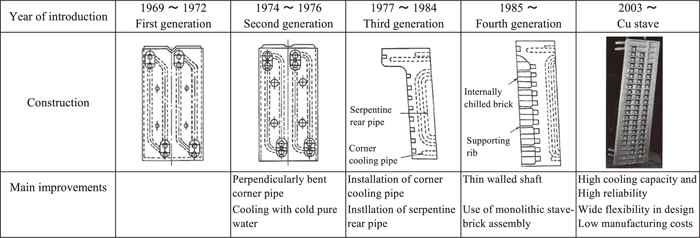
The shaft and hearth had governed blast furnace service life up to the early 1980s (Fig. 19). As a result of improvement of the cast iron staves (Fig. 20),53) development of cast copper staves, and development of bosh stave exchange technology, the factors governing service life are now limited to the hearth, including the side wall and furnace bottom, which cannot be repaired or improved during a long time stop.4)
In the 1990s, strengthening the corrosion resistance of the hearth wall was recognized as the most important factor for extending hearth life, leading to improvements in carbon brick materials and strengthening of cooling.53) In particular, carbon bricks have been developed to increase thermal conductivity and prevent molten iron penetration by reducing the brick pore size.55) In 1986, the service life of large blast furnaces was over 10 years, with cumulative production of 38 million tons and cumulative productivity of 6000 to 8000 t/IVm3. However, following improvements in blast furnace cooling capacity, furnace wall repair, and control technology for inhibiting circular molten iron flow, the number of blast furnaces with a service life over 15 years has increased. Sumitomo Metal Industries Wakayama No. 4 blast furnace (inner volume: 2700 m3), which was shut down in July 2009, set a record for the longest service life at 27 years and 4 months. Among other blast furnaces with inner volumes exceeding 4000 m3, Kawasaki Steel Chiba No. 6 blast furnace (inner volume: 4500 m3) was shut down in March of 1998 after setting a service life record of 20 years and 10 months. Thus, service life extension technologies for realizing furnace life of over 20 years are well established in Japan.
4.5.2. Introduction of Labor Saving Appliances, Expansion of Blast Furnace Volume, and Advances in Blast Furnace Short-Period Revamping Technologies
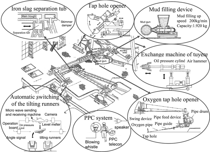
Mechanization and remote operation technologies were introduced for labor saving and comfort in casting operations (Fig. 21).53) Equipment which has been introduced includes, for the tap hole area, hydraulic tap hole openers, oxygen tap hole openers, hydraulic mudguns, mud filling devices, automatic molten iron samplers, and trough covers and traversers for preventing generation of dust; for the tilting trough area, monitoring cameras and hot metal level gauges for the torpedo car; and for the work floor, tuyere and blow pipe exchange units.4) Labor saving technology, wireless control, and remote operation for cast floor machinery have been realized in line with improved machinery reliability. As examples of progress in wireless control of cast floor machinery, one-man operation using whistle signal processing and remote operation from the control room using monitor displays have been adopted. Kawasaki Steel adopted a flattened cast floor at Chiba No. 6 blast furnace during the revamping in 2000.163) As a gas cleaning system, dry dust collection equipment was introduced to improve the efficiency of the top gas pressure recovery turbine (TRT). The development of these various types of labor-saving equipment provides a solid foundation for the stable operation of large blast furnaces.
The changes in the inner volume of blast furnaces operating since 1955 are shown in Fig. 22. In Japan, the first blast furnace started operation in 1901 with an inner volume of 500 m3, and blast furnaces with inner volumes of 1000 m3 appeared in 1940. Use of furnaces with inner volumes in the 1200 m3 range continued after World War II, but from 1958, increases in blast furnace inner volume began to accelerate. In the following period of about 20 years, inner volume increased by 4 times with the construction of a large blast furnace over 4000 m3 in 1971 (NKK Fukuyama No. 4 blast furnace, inner volume: 4197 m3) and an inner volume on the order of 5000 m3 in 1976 (Sumitomo Metal Industries Kashima No. 3 blast furnace, inner volume: 5050 m3). After a temporary hiatus in this upward trend, blast furnace expansion resumed from the beginning of 2000, and Nippon Steel’s revamped Oita No. 2 and Oita No. 1 blast furnaces attained inner volumes of 5775 m3 in 2004 and 2009, respectively. This is the largest inner volume in Japan to this day. As of 2013, 27 blast furnaces were in operation in Japan, of which 20 were large blast furnaces with inner volumes exceeding 4000 m3. The background for this expansion of furnace volume during revamping includes the fact that it has become possible to reduce total stave thickness from 600 mm to around 150 mm thanks to the increased cooling capacity obtained as a result of stave structural improvements.

In the area of blast furnace repair technology, in 1998, Kawasaki Steel realized an ultra-short revamping period of 62 days at Chiba No. 6 blast furnace. This was achieved by applying the large block ring construction method (Fig. 23).54) The large-module method was also used during improvements at Nippon Steel Nagoya No. 3 blast furnace in 2000.53) Technologies for expanding the range of prior fitting and increasing block weight by the hearth integral pullout method (in which the hearth is removed in a single unit) were developed for the revamp (third campaign) of Nippon Steel Oita No. 2 blast furnace in 2004, resulting in the completion of improvements in a short construction period of 79 days, while also expanding the inner volume of the furnace.
4.6. Instrumentation, Control, and System Technologies
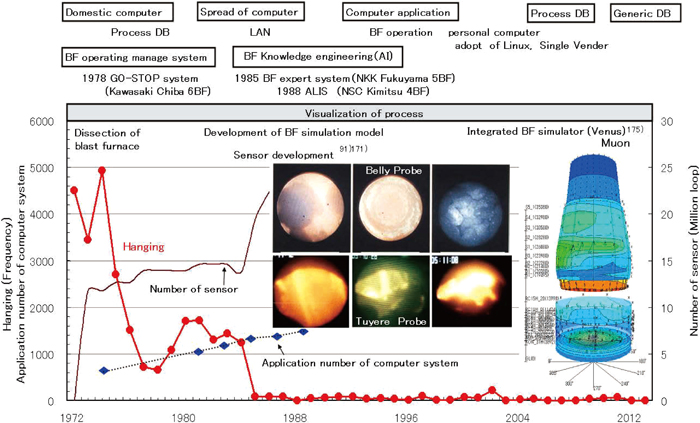
As long as the inside of the blast furnace remains a so-called “black box,” blast furnace engineers must rely on their experience and intuition in order to take appropriate operational actions such as adjusting RAR and burden distribution or changing blast conditions when operation becomes unstable.164) In order to obtain stable blast furnace operation, operation control systems based on knowledge engineering and operational experience were developed around 1980 and have been widely deployed, taking advantage of advances in computer technology. Following dissection studies of blast furnaces, visualization of the in-furnace condition by the development of various types of probes, information systems utilizing sensors mounted in various parts of the blast furnace, and the development of simulation models has led to advances in monitoring of the inner state of blast furnaces in operation.165,166,167) Presumably as a result of various R&D projects, such as application of operation control systems, burden material control, and equipment engineering improvements, as described above, the frequency of hanging drastically decreased from 1985, and blast furnace operation has been stable since that time (Fig. 24).
The use of computers in ironmaking began in the 1960s. During that period, computerization included applications such as weighing control of burden materials, blast control (blast air flow rate and pressure, prevention of surging), various pressure control systems for high pressure operation, tuyere-by-tuyere heavy oil injection flow rate control, tuyere combustion temperature control, and hot stove control (dome temperature, combustion and furnace switching, gas calorie control). In the field of operation data systems, data logger functions for operation results and sensor information on furnace body management were expanded and used in early detection of operational problems and analysis. As computers increased in speed, general-purpose LANs were adopted, enabling processing of large amounts of data for blast furnace instrumentation and control systems.
In 1964, Nippon Kokan tested a blast furnace reaction control system at Kawasaki No. 5 blast furnace with the objective of controlling the furnace heat condition. In 1973, a system comprising theoretical and statistical models of both furnace heat and permeability, which were supplemented by probe information and empirical rules, was introduced at Nippon Steel Sakai No. 2 blast furnace.
In 1978, Kawasaki Steel installed its GO-STOP system168) Chiba No. 6 blast furnace. This was an operation control system that provided operational guidance based on quantified and visualized real-time changes in blast furnace status by using a weighted furnace index of the blast furnace operation state (comprising eight furnace state indices relating to burden descent, permeability, furnace heat, and the tapping slag and hot metal balance) and four indices of furnace fluctuation (permeability and furnace heat). In 1985, as knowledge engineering progressed, expert systems which made use of knowledge bases and inference engines and problem-solving methods which combined a number of AI methods such as neural networks and fuzzy logic were introduced as blast furnace operation control systems. In 1986, an expert system169) which realized online real-time processing by integrating process processor (plant control system) and AI processor (inference system) functions was implemented at Nippon Kokan Fukuyama No. 5 blast furnace during its second revamping. This system was configured of two subsystems, a furnace fault state diagnostic system and a furnace control expert system. The blast furnace operation control system ALIS170) at Nippon Steel Kimitsu No. 4 blast furnace was also based on an expert system which used knowledge engineering, and during the 2003 revamp, incorporated distributed processing, web technologies, and visualization technologies.
Various projects related to technologies for visualizing in-furnace phenomena106) were carried out after the blast furnace dissection studies around 1970. New sensors were developed for direct measurement inside the blast furnace; this included a rigid vertical probe equipped with a fiber scope120) at Nippon Steel Muroran Works, a furnace belly probe at Nippon Steel Oita No. 2 blast furnace,159,171,172,173) and a tuyere probe174) and sideways tuyere probe160) at Kawasaki Steel Chiba No. 5 blast furnace.
In the 2000s, Nippon Steel developed a visualization system called VENUS175) which graphically shows stave temperature profiles by creating an isothermal diagram, making it possible to learn the blast furnace radial and vertical heat load distribution of the furnace wall. VENUS serves as an operation improvement tool by combining these time-series transition data with similar information from the past and applying the results to early identification of gas flow problems inside the furnace, to estimating the cohesive zone root, and to other operation analysis problems. Recently, cosmic ray muons have been used to develop a visualization technology for the inside of a blast furnace.176,177)
4.6.2. Development of Blast Furnace Simulation Models
The complexity of the behavior inside the blast furnace has led to the development of mathematical models which provide a powerful means of understanding the behavior inside the furnace. The first models developed to analyze blast furnace processes involved the overall heat and mass balances. Subsequently, process models consisting of differential equations for heat and mass transfer were developed. As an example of the former, the RIST model,178) which uses an operating line predicated on the existence of a chemical reserve zone, was proposed in the 1960s and is still widely used in operation analysis. The latter was promoted by Muchi et al.179) in the late 1960s, and a one-dimensional steady state blast furnace model capable of analyzing reaction and heat transfer behavior was developed. In 1982, this model was developed into a one-dimensional transient model that was applied to simulate transient operations such as blast furnace blow-in and blown-out.
After blast furnace dissection studies revealed the existence of the cohesive zone, researchers took up the challenge of developing a two-dimensional model for simulation of gas flow and heat transfer (including those in the radial direction) and their effects on reduction. Using a multi-dimensional Ergun’s equation, which was proposed as a basic momentum equation for calculation of gas flow in a packed bed, Hatano,180) Kuwabara,181) Yagi,182,183) and Sugiyama184) et al. developed the world’s first two-dimensional steady state blast furnace model in the early 1980s, and that model has served as a tool to elucidate behavior inside the furnace.
Thereafter, blast furnace model development split into two directions. One was model development oriented toward application to actual operation, which enables simulations reflecting changes in operation actions such as burden distribution control and changes in the quality of burden materials. The other was development of a model whose object was blast furnace analysis capable of reflecting the effects of transient phenomena and multi-phase flows.
The former, as exemplified by the model proposed by Naito et al.,185) was constructed within the framework of a two-dimensional steady state model and improved the analysis precision of each sub-model. The burden distribution control model RABIT,149) sinter reducing model (multi-stage reaction zone model186)),185) high temperature properties evaluation model, and other models were incorporated as sub-models.187) Validation of the blast furnace models was carried out, including issues such as measurement of hot metal residence time by a radioactive element tracer, gas flow inside the furnace, research on evaluation of the high temperature properties of sinter and lump ores, research on reduction, and the reaction behavior of sinter and coke mixtures under simulated blast furnace conditions.113,115,185) Thanks to rapid progress in computer performance, these models are now used by engineers as on-site blast furnace simulators which enable calculation on a notebook computer.
The latter, i.e., models treating transient phenomena and multi-phase flows, were studied by Nogami et al.188) and Takatani et al.189) These were extensions from two to three dimensions, from the steady state to transient phenomena and to multiphase flows (including fine particle flows), and were mostly completed around 2000 (Fig. 25).
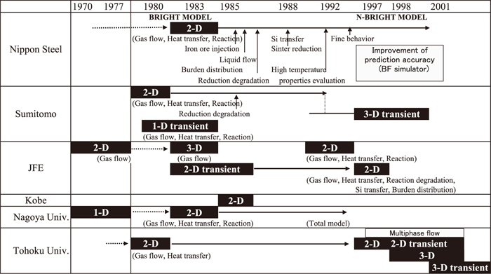
Accompanying the dramatic increases in computer performance and speed during the 2000s, analysis using the discrete element method (DEM)190,191,192) has been studied extensively. DEM is effective in discontinuous analysis of flow and blending behavior and other factors involving granular and powdery materials. In the ironmaking field, DEM was applied to analysis of burden distribution control, solid flows inside the furnace, and the particle flow in the raceway, as well as to analysis of the iron ore granulation process and analysis of the sintering and cokemaking processes. Recently, the moving particle semi-implicit method (MPS), which is a numerical technique using discrete values for continuous phases, has been studied in connection with analysis of liquid dripping behavior in the coke packed bed,193) and further application and development are expected.
5. Development of Next-Generation Low Carbon Technologies
Reduction of the amount of carbon material used in the blast furnace through operational and raw material quality improvements is now near its theoretical limit, which is controlled by the reduction equilibrium and heat balance in the furnace, and no large reductions can be expected in the future. This is the background behind efforts by industry, government, and academia to devise breakthrough technologies that enable dramatic reductions in CO2 emissions. Generally, efforts to achieve significant reductions in CO2 emissions, mainly in the blast furnace, are divided into two approaches: (1) Decreasing RAR by using reduction equilibrium control and (2) Introduction of new functions to the blast furnace itself and development of new processes based on CO2 separation and carbon capture and storage (CCS).
Figure 26 shows a general schedule for Japanese and international projects involving next-generation low carbon technologies. Because developments from the conventional sinter, coke, and blast furnace processes face considerable hurdles, industry, academia, and government have joined together in major projects and are moving forward with development while receiving public support.
5.1. Carbon Reduction through Reduction Equilibrium Control
As shown schematically in Fig. 27, increasing the reactivity of carbon material makes it possible to lower the solution loss reaction start temperature, shift the reduction equilibrium point W from point B to point C, and then reduce RAR. Reductions in RAR have been demonstrated by using highly reactive nut coke113) at Nippon Steel Oita No. 1 and No. 2 blast furnaces, and a RAR reduction of about 10 kg/thm was achieved at Nippon Steel Muroran No. 2 blast furnace (inner volume: 2902 m3) by using high Ca coke115) whose reactivity was raised by catalysis of CaO in ash. A 5 year research project with the aims of halving blast furnace energy consumption and minimizing the environmental load of the blast furnace was carried out, beginning in 1999, as a Special Coordination Funds for Promoting Science and Technology general research project.57) The program has found that a coupling reaction of iron ore reduction and CO regeneration can be used as a technology for accelerating and lowering the temperature of reduction and the gasification reactions by close arrangement of ore and coal by mixed grinding. It was also shown that the reduction equilibrium reaction can be reduced by about 150–200°C by manufacturing a carbon composite iron ore hot briquette (hybrid agglomerate) by agglomeration, exploiting the thermoplasticity of coal.59,114) Next, in the Iron and Steel Institute of Japan’s Research Group “Control of reduction equilibrium in blast furnace through close arrangement of iron ore and carbon” (2007–2010), systematic research on the gasification and reduction rates was conducted for ore-carbon distances from the centimeter to the nanometer order of magnitude, as shown in Fig. 28.60)
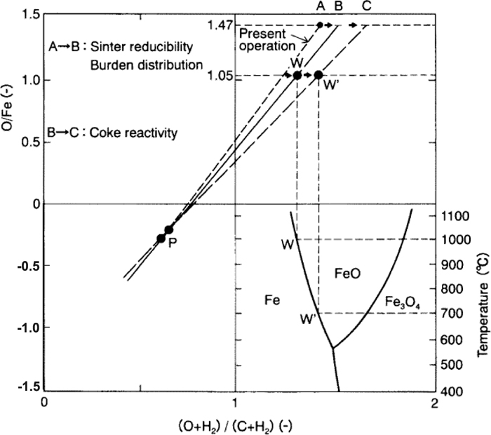

Based on the fundamental knowledge gained in this research, “R&D and preparatory research work for the blast furnace based on innovative ironmaking technologies” was organized as contract research of the New Energy and Industrial Technology Development Organization (NEDO) in 2006. That project led to proposals for “Development of innovative ironmaking process using low cost iron ore and coal”58) in 2008. A quantitative evaluation of acceleration of the gasification reaction speed of carbon by close arrangement of carbon and iron oxide and by the catalytic effects of the gasification reaction of metallic iron/iron oxide was carried out, and manufacturing methods were studied for carbon-containing agglomerated ore (ore containing fully dispersed carbon) and ferrocoke (carbon containing fully dispersed metallic iron or carbon iron composite (CIC)) and their thermal reserve zone temperature drop and RAR reduction effects.
A project entitled “Pilot scale development of innovative agglomerate manufacturing and blast furnace operation technologies” was carried out from 2009 to 2012 as joint research involving JFE Steel Corporation, Nippon Steel & Sumitomo Metal Corporation, Kobe Steel, Ltd., and major universities in Japan with subsidies from NEDO and the Ministry of Economy, Trade and Industry (METI). As shown in Fig. 29, manufacturing technologies at a 30 t/d pilot plant, an innovative binder, and blast furnace operation technologies were developed for ferrocoke, which is a composite agglomerate of iron oxide, metallic iron, and carbon material. Charging tests at a large blast furnace were conducted using ferrocoke that had been stockpiled during long-term manufacturing tests in order to verify the reduction of RAR and identify issues for industrial-scale application.194,195,196)
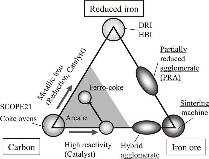
For carbon iron composite (iron oxide containing dispersed carbon), Kasai et al.197) performed a short-period test of the use of carbon composite iron ore hot briquettes at Kobe Steel Kakogawa No. 3 blast furnace (inner volume: 4500 m3), and Yokoyama et al.198) manufactured 21000 tons of the carbon-containing agglomerated ore RCA (Reactive Coke Agglomerate) and tested its use at Nippon Steel Oita No. 2 blast furnace (inner volume: 5775 m3). A reduction in carbon consumption of 0.36 kgC/thm per 1 kg/thm of carbon in the RCA and, as shown in Fig. 30, a drop in the thermal reserve zone temperature of 83°C were demonstrated.
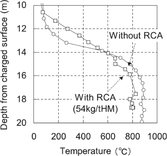
In the development of low carbon blast furnace technologies through reduction equilibrium control, evaluation tests at blast furnaces have already been completed using hot molded briquettes, carbon-containing agglomerated ore, and ferrocoke. The next stage will be evaluation of economic feasibility at the industrial scale and study of the effect of using these raw materials on the energy balance in the steel works.
5.2. Low Carbon Operation by Intensified Gas Reduction in the Blast Furnace
While reduction of input carbon is limited by the reduction equilibrium of gas in the furnace, further decreases in RAR can be achieved by lowering the direct reduction ratio (an endothermic reaction) by strengthening gas reduction inside the blast furnace through decarbonization and recirculation of top gas by injection into the furnace.
During the 1970s, Japanese researchers investigated reduction of RAR by injecting reducing gas into the blast furnace shaft. The FTG process, in which reducing gas is manufactured by partially oxidizing heavy oil and injecting the product into the shaft, was implemented at Nippon Steel Hirohata No. 3 blast furnace (inner volume: 1691 m3).199) Injection of reducing gas manufactured from 30 kg/thm of heavy oil achieved a RAR reduction at a replacement ratio of 0.9 to 1.0. The radial diffusion of gas injected into the shaft was relatively small, and as the gas rose, it spread at an angle of about 15° as a result of turbulent diffusion in the packed bed. The NKG process, in which a high temperature reducing gas is injected into the shaft, was also proposed. The reducing gas was produced from the CH4 component of coke oven gas by reforming, using CO2 from the blast furnace top gas, which was selectively recovered from around the furnace top.200)
COURSE50 (CO2 Ultimate Reduction in Steelmaking Process by Innovative technology for cool Earth 50), which is discussed in more detail in the following section, is a national project commissioned by NEDO targeting reduction of carbon emissions by strengthening blast furnace reducing functions. Significant reductions of CO2 emissions have been achieved since the project began in 2008.
5.2.1. COURSE50 Project
The COURSE50 Project was begun in 2008 as an attempt to reduce CO2 emissions by further developing the technique of injecting reducing gas into the blast furnace shaft, in combination with H2 amplification by reforming coke oven gas.201) COURSE50 is a low carbon process comprising technologies for reducing CO2 emissions from the blast furnace and technologies for separating and recovering CO2. It aims to contribute to the low carbon blast furnace technologies of a 30% reduction in CO2 emission.
The hydrogen reduction technology proposed by the COURSE50 Project consists of hydrogen amplification by gas reforming of coke oven gas, hydrogen ore reduction technology, and cokemaking technology for hydrogen reduction blast furnaces. Phase I (Step 1) development was carried out over a 5 year period beginning in 2008, and Step 2, partial verification at a mini-test blast furnace, began in FY2013 and is also a 5 year development project. As shown in Fig. 26, the COURSE50 process is an extension of the earlier FTG and NKG processes, in which reducing gas was injected into the blast furnace shaft.
From the momentum balance of two gases, it has been found that the penetration area of shaft injection gas is proportional to the injection gas rate200) and iron ore reduction is promoted by hydrogen.202) However, because hydrogen reduction is an endothermic reaction, special attention must be paid to securing the temperature at the furnace top. Phase 2 planning is underway targeting the first deployment of this technology at an industrial-scale blast furnace in 2030, preconditioned on establishment of CO2 sequestration technology and economic feasibility.203)
5.2.2. European ULCOS Project
The Ultra low CO2 Steelmaking (ULCOS) Project (ULCOS I) was carried out from 2004 to 2010 with the participation of 48 European companies and research centers and research funds of 76 million euros,204) with receiving financial assistance from the Research Fund for Coal and Steel (RFCS), which supports coal and steel technological research in the EU. Facing the challenging target of achieving a 50% reduction in CO2 emissions, a broad-based process evaluation covering a range of technologies from smelting reduction to electrolysis steelmaking was carried out, and four technologies, ULCOS-NBF (ULCOS-New Blast Furnace), HIsarna (coal-based smelting reduction process), ULCORED (natural gas-based direct reduction), and ULCOWIN/ULCOLYSIS (electro winning) were selected for development in the next step. Their development is currently underway under the name ULCOS II, aiming at completion by FY2015.
As shown in Fig. 31, ULCOS-NBF is based on the oxygen blast furnace, and is characterized by removal of CO2 from the top gas and heating and injection of the recirculated gas into the shaft and tuyeres.205) The process concept is similar to the oxygen blast furnace of Ohno et al.,206) the blast furnace top gas circulation of Nishio and Miyashita,200) and the further developed oxygen compact blast furnace process proposed by Murai et al.207) Test operation of ULCOS-NBF took place at the Swedish LKAB test blast furnace (inner volume: 8.2 m3), and based on the results, Version 4 (heated high temperature gas injection to shaft and tuyeres) achieved an estimated 24% reduction of carbon input without CCS and a maximum 73% reduction of CO2 emissions with CCS.208) However, it should be noted that energy supply to the downstream processes was not considered in the evaluation. The ULCOS II project includes plans for testing without CSS at the Eisenhuttenstadt blast furnace in Germany in 2014 and plant trials in combination with CCS at the Florange blast furnace in France in 2016. In order to realize these developments at an industrial scale, long-term development extending over a further 15 to 20 years is considered necessary.
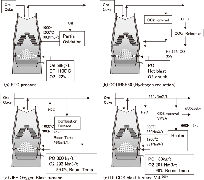
Low carbon technologies other than the blast furnace process include the above-mentioned ULCOS HIsarna (smelting reduction process) of the ULCOS project209) and the FINEX process, which is an alternative ironmaking process that does not require a sintering machine or coke oven and was developed and deployed by POSCO in Korea.210) Process development of FINEX began in 1992 and led to successive development of a 15 t/d model plant in 1996, a 150 t/d pilot plant in 1999, and a 600000 t/y demonstration plant in 2003. The first full-scale plant operation at 1.5 million t/y was achieved in 2007, followed by a second plant with a capacity of 2 million t/y in 2013. As features of the FINEX process, generated gas from the melting gasification furnace is conveyed to a 4-stage fluidized bed, and reduced iron is supplied to the melting gasification furnace. A 4% reduction in CO2 emissions in comparison with current blast furnaces could be achieved by reducing coal consumption by various measures, such as separating CO2 from the off-gas from the fluidized bed and recirculating it back to the process upstream of the fluidized bed. Because pure oxygen is used and the concentration of CO2 in the gas is high, significant CO2 reduction is feasible when used in combination with CCS.210)
The HIsarna process is a process by which reduction and melting of fine ore are performed in a cyclone converter furnace (CCF), and smelting reduction is performed in a smelting reduction vessel (SRV). The objective of this process is to achieve a substantial reduction in CO2 emissions by using pure oxygen and combining the process with CCS. Test operation started in 2011 at a pilot plant (nominal capacity: 8 thm/h) at Ijmuiden Tata Steel, and test operation under the ULCOS II project is scheduled for the period from 2012 to 2014.209)
To summarize the state of the next-generation low carbon technologies described in Chapter 5, most of the next-generation low carbon processes except for FINEX are currently in the pilot plant development stage, but a number of issues, as outlined below, remaining before development to the commercial stage.
(1) Plant engineering and operation cost optimization: Building a business model in which new plant investment becomes economically feasible.
(2) Development of energy infrastructure: Because use of a low carbon blast furnace reduces the amount of fuel gas supplied to the downstream processes in the steel works, development and investment to create an energy infrastructure that can compensate for the shortage of energy supply in the steel works will be necessary.
(3) Process verification at the intermediate scale: Verification before development to a commercial plant in order to reduce scale-up risks.
6. Resource, Environmental, and Alternative Ironmaking Technologies Promoted in Japan
Alternative ironmaking technologies promoted in Japan include the continuous steelmaking process (1964–1983), nuclear ironmaking (1973–1978), the smelting reduction process (DIOS: 1988–1995), rotary hearth furnaces (RHF: 1995–2000), and various coke packed bed shaft furnaces. As typical examples, DIOS, coke packed bed shaft furnaces, and RHF are discussed in the following sections.
6.1. Smelting Reduction Process
During the eight years from 1988, the smelting reduction process DIOS (Fig. 32) was developed in a national project as an alternative ironmaking process to the blast furnace. DIOS features an adjustable production rate and flexibility in the selection of raw materials.109) Pre-reduction of iron ore is carried out in a 2-stage fluidized bed, and smelting reduction is carried out by direct use of coal in a smelting reduction furnace. As features of this process, the reduction ratio in the fluidized bed is relatively low, at below 30%, and most reduction is carried out in a smelting reduction furnace.

Based on the outcome of the first three years of elemental research, a 500 t/d demonstration furnace was built, and a total of ten test operation campaigns were conducted from October 1993 to January 1996 to demonstrate the feasibility of the process. Based on the results, coal unit consumption in a commercial-scale plant was estimated at 730–750 kg/thm. Two smelting reduction furnaces are required in a 6000 t/d scale commercial facility, but because coke oven or sintering machine is unnecessary, facility cost reductions of 35% and manufacturing cost reductions of 19% could be achieved in comparison with the blast furnace process. With the aim of commercialization, various engineering designs were proposed and feasibility studies were carried out with the objectives of increasing productivity, reducing the heat load on the smelting reduction furnace, simplifying the facilities, etc. One of the resulting proposals, Duplex-DIOS, is a process in which pre-reduction is strengthened by use of DIOS in combination with a rotary hearth in order to reduce the heat load on the smelting reduction furnace. Commercialization of this technology was proposed, including overseas. The smelting reduction technology in the DIOS process has also influenced other smelting reduction methods such as HIsmelt and HIsarna.
6.2. Coke Packed Bed Shaft Furnace
The two-stage tuyere smelting reduction furnace STAR (STainless steel Advanced Reactor)47) at Kawasaki Steel Chiba Works and the multi-function melting furnace MFMF (Multi-Function Melting Furnace)50,51,211) at Nippon Steel Nagoya Works are examples of shaft furnaces which employ a coke packed bed.
The STAR furnace was developed and constructed at Chiba Works for processing of byproducts such as stainless steel dust and slag (Fig. 33(a)). Coke is supplied from the furnace top, while the stainless steel dust fines that serve as the main raw material are injected from the upper stage of a two-stage tuyere, which is mounted on the bottom of the furnace. The dust is mainly reduced and melted in the raceway.
MFMF, which is a shaft furnace with a two-stage tuyere configuration, uses blast furnace coke for both reduction and carburization of ironmaking dust and steel scrap in order to produce molten iron (Fig. 33(b)). Ironmaking dust is pelletized and charged from the furnace top together with steel scrap and coke. The first MFMF (inner volume: 67 m3) was constructed at Nagoya Works in 2005. In 100% steel scrap operation with blast furnace coke, low coke rate operation was achieved at a tapping rate of 22 t/d/m3 and CR of about 190 kg/thm by utilizing two-stage blowing.211)
6.3. Rotary Hearth Furnace
Table 3 shows a classification of the direct reduction processes which are currently under development or in operation worldwide by furnace type, temperature, and reducing agent.212) Shaft furnace processes for gas reduction of fired pellets, such as the MIDREX process, are predominant; however, depending on the reducing agent supply, rotary kiln processes, in which reduction is performed in a rotary kiln by carbon outside of the agglomerate, are also used. A rotary hearth furnace (RHF) process that uses agglomerated ore with mixed coal has also been developed and commercialized, mainly for dust processing in steel works.
Table 3. Classification of DR plants by reductant source, furnace type and reduction temperature.
Because carbon-iron ore agglomerates generally have low handling strength, the rotary hearth furnace, which is capable of heating and transporting the material in a static state, is used as a reduction process for these materials (Fig. 34).213) RHF was developed as a process targeting a zero-emission steel works, waste recycling, and enhanced environmental friendliness.
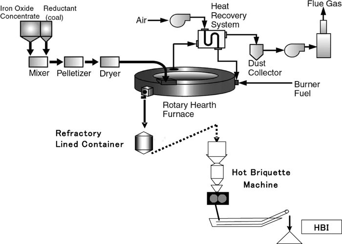
In the high temperature range of RHF temperatures from 1300°C to 1350°C, the carbon gasification reaction (solution loss) accelerates the direct reduction reaction of iron ore. When using carbon iron ore composite formed by mixing fine solid carbon and iron oxide, high speed reduction at temperatures lower than that of blast furnaces and smelting reduction processes are possible because the solution loss reaction progresses at a low temperature. In addition, the RHF has also been operated at a high temperature of about 1300°C with carbon mixing. This process is suitable for recovering valuable metals from steelmaking dust and sludge with high vapor pressure metals at relatively low temperature, and especially from electric arc furnace dust and mill scale with high Zn and Pb concentrations.
The RHF (diameter 21.5 m) at Nippon Steel Hirohata Works processes 190000 t/y of steel dust. Metallization of 91.9% and zinc removal of 94.0% have been achieved at a RHF productivity of 100 kg-DRI/m2h. Subsequently, a continuous process for manufacturing molten iron from dust DRI was established by adding DRI melting furnaces near the RHF to improve thermal efficiency and promote recycling. At present, four RHFs are in operation with a processing capacity of about 600000 tons/year.214) At Nippon Steel Kimitsu Works, 600000 tons/year of dust generated in the works is processed by three rotary hearth furnaces with annual capacities of 130000 to 300000 tons/year. Coarse reduced pellets are recycled to the blast furnace, and reduced iron fines are recycled to the sintering process. The strength of the reduced pellets (metallization: 70–85%) is controlled to at least 50 kgf/cm2 for blast furnace use. Use of these pellets is contributing to reduction of RAR at the blast furnace.46,215)
Slag-free nugget/pebble production processes have been developed as new advances in RHF technology. These include Kobe Steel’s ITmk3 (Ironmaking Technology mark three)48) and JFE Steel’s Hi-QIP (High Quality Iron Pebble).49) Conventional DRI produced from carbon-iron ore agglomerates contained large amounts of gangue because the iron ore was reduced in a solid state, and this was a disadvantage compared to steel scrap. When carbon material-containing agglomerated ore is rapidly heated and reduced at high temperatures in the range of 1350 to 1500°C, iron and slag start melting in the final stage of the reaction, and gangue minerals can be separated.216)
In the ITmk3 process, heating and reduction are carried out at 1350°C in a solid state, and the temperature is then raised to 1400 to 1450°C at the end of the reaction. Therefore, melting and separation of slag from the metal occur in the furnace, and the FeO content of the molten slag is a low 1% or less.217,218) A typical chemical composition of the nuggets is TFe 96–97%, C 2.5–3.5%, and S 0.05%. On the other hand, in Hi-QIP, heating and reduction are performed at the high temperature of 1500°C, and during the final stage of reduction, the metallic iron and high FeO-containing slag are melted and react with the carbon in the hearth layer, and the metal and slag are separated.49) The hearth carbon layer protects the hearth brick from the generated high FeO slag, and also performs the role of supplying carbon. Because the nuggets/pebbles obtained from these processes are essentially slag-free, reactivity associated with melting is reduced, and easy handling and a considerable reduction of steelmaking costs can be expected.
In the new ironmaking processes described above, the following patterns of process diversification can be observed: While pre-reduction to smelting reduction is the major process concept of the DIOS process, and simultaneous melting and reduction is the main concept of the coke packed bed-type STAR furnace, melting after reduction is the key process concept of the RHF and coke packed bed-type MFMF furnace. As the heat transfer mechanism, DIOS and the coke packed bed-type shaft furnace use convective heat transfer, while the RHF uses radiant heat transfer. This diversification of process concepts is a typical example of Japanese ironmaking technologies, whose technological bases have evolved in an environment of limited natural resources.
7. Future Prospects
Looking back over this 100 year history, the Japanese steel industry has experienced boom-and-bust cycles, but has constantly played a significant role in the growth of the Japanese economy as a key industry which supplied basic materials for social infrastructure development in both the prewar and postwar periods. While most of the basic technologies of modern steelmaking were introduced from Europe, the United States, or the former Soviet Union, those technologies were painted with a Japanese brush by our predecessors, who also introduced cutting-edge technologies such as computer control and automation, promoted enlargement of facilities, and recognized the importance of investing in energy saving technology and environmental measures. As a result, those technologies ultimately were flowered into competitive original Japanese technologies.
For various reasons, it would be difficult to forecast Japanese and international energy prices. In particular, the Fukushima nuclear power plant accident caused by the Great East Japan Earthquake of 2011 led to at least a temporary shutdown of all nuclear plants in Japan, and shale gas production is enjoying remarkable growth, especially in North America. On the other hand, demand for mineral resources by the steel industry has eased recently due to a slowdown in the Chinese economy, which achieved enormous growth in a short period of time. Thus, in the near term, movements in energy and mineral resource prices that affect the steel industry will fluctuate considerably, depending on the balance of supply and demand.
As experienced in the development and commercialization of SCOPE21, the development of new ironmaking technologies requires a long period of at least ten years. For this reason, it is important for industry, government, and academia to collaborate and steadily promote development of universal issues, which are not influenced by short-term economic factors. The following may be mentioned as examples:
1) Facility and operation technologies aimed at low coke rate operation of the blast furnace
Japanese coke ovens have steadily aged and become obsolete, and most will require revamping by 2025. Efforts to reduce the coke rate to its lowest limit are crucial for keeping capital investment to the minimum in the current era of low economic growth.
2) Technologies for expanding use of low grade resources
The world’s iron ore, coal, and ferroalloy resources are steadily deteriorating in quality, while prices remain at a high level. One way to maintain the competitiveness of Japan’s steel industry is to use relatively cheap (and generally difficult to use) resources in order to reduce the hot metal cost. For this purpose, projects for reexamination of blast furnace facilities and operation from the standpoint of using cheap resources are already underway.
3) Carbon reduction and energy saving in ironmaking
The trends of the international initiatives to mitigation of global warming gases will strongly affect R&D activities for CO2 emissions reduction as a global warming prevention countermeasure. Although such initiatives are under discussion, whatever form they may take, the needs for energy saving and reduction of CO2 emissions will remain key issues for ironmaking over the long term. There is a need to continue efforts to develop low carbon technologies, such as new ironmaking processes, and to commercialize the new agglomerates which are currently under development.
4) Optimization of ironmaking processes considering global supply and demand of steel scrap
As the economies of emerging countries reach maturity, their steel scrap balance will change to surplus in the future. Based on this, it is important to optimize the capacity ratio of scrap-based ironmaking processes to iron ore-based ironmaking processes.
In order to promote these new technological developments, further joint efforts will be required among industry, government, and academia, including the research group of the Japan Society for the Promotion of Science 54th Committee on Ironmaking, the joint research group of the Iron and Steel Institute of Japan, and national projects of NEDO and METI. To paraphrase, it is often said that “the deeper one can see into the infinite distances of the past, the further one can see into the limitless distances of the future.” There may be many technological developments which have not been commercialized, or which sometimes went unpublished and now lie buried in the past. Writing this review is a good opportunity to reevaluate all the technologies of the past from a fresh perspective, while remember the admonition to “Beware of imitation, and employ creativity”.104)
Acknowledgement
We hope that this work will serve as a useful textbook for the younger engineers and researchers of next generation when looking back on the history of the steel industry, and that it will contribute to a renewed appreciation of the labors of our predecessors.
References
- 1) M. Kase, M. Sugata, K. Okuda, Y. Umezu, S. Amano, H. Ono and C. Mizuuchi: Tetsu-to-Hagané, 67 (1981), S82.
- 2) A. Suzawa, Y. Okuno, T. Deno, T. Imai, K. Suzuki and E. Chikamatsu: Tetsu-to-Hagané, 67 (1981), S84.
- 3) S. Kajikawa, R. Yamamoto, R. Nakajima, J. Kishimoto and T. Fukushima: Tetsu-to-Hagané, 68 (1982), 2361.
- 4) M. Naito: 179th Nishiyama Memorial Seminar, ISIJ, Tokyo, (2003), 89.
- 5) N. Sakamoto, H. Noda, Y. Iwata, H. Saito and T. Miyashita: Tetsu-to-Hagané, 73 (1987), 1504.
- 6) A. Oboso, T. Shouho, K. Tajiri and K. Ohne: CAMP-ISIJ, 10 (1997), 190.
- 7) Y. Matsukura, K. Nakano, K. Sunahara, Y. Ujisawa and T. Yamamoto: Tetsu-to-Hagané, 87 (2001), 350.
- 8) T. Inazumi, M. Fujimoto, S. Kasama and K. Sato: Tetsu-to-Hagané, 77 (1991), 63.
- 9) D. Shibata, T. Haga, A. Ohsio, S. Kasama and K. Watanabe: CAMP-ISIJ, 14 (2001), 193.
- 10) N. Oyama, K. Igawa, K. Takeda, T. Ariyama and T. Jinno: Tetsu-to-Hagaé, 90 (2004), 546.
- 11) T. Haga, A. Ohshio, K. Nakamura, T. Kozono and K. Uekawa: Tetsu-to-Hagané, 83 (1997), 103.
- 12) K. Higuchi, T. Kawaguchi, M. Kobayashi, Y. Hosotani, K. Nakamura, K. Iwamoto and M. Fujimoto: ISIJ Int., 40 (2000), 1188.
- 13) H. Uematsu, Y. Ishida and K. Kushioka: Ironmaking Conf. Proc., Vol. 48, ISS, Warrendale, PA, (1989), 109.
- 14) S. Wakuri, M. Ohno, K. Hosokawa, K. Nakagawa, Y. Takanohashi, T. Ohnishi, K. Kushioka and Y. Konno: Ironmaking Conf. Proc., Vol. 45, ISS, Warrendale, PA, (1986), 303.
- 15) Y. Nakashima, S. Mochizuki, S. Ito, K. Nakagawa, K. Nishimoto and K. Kobayashi: 2nd Int. Cokemaking Cong., The Institute of Materials, London, UK, (1992), 518.
- 16) N. Tsuchiya, M. Tokuda and M. Ohtani: Tetsu-to-Hagané, 58 (1972), 1927.
- 17) K. Tamura, K. Ono and N. Nishida: Tetsu-to-Hagane, 67 (1981), 2635.
- 18) N. Tsuchiya and S. Taguchi: Tetsu-to-Hagané, 69 (1983), 1945.
- 19) K. Kushima, M. Naito, K. Sibata, H. Sato and H. Yoshida: Tetsu-to-Hagané, 75 (1989), 1286.
- 20) C. Yamagata, Y. Kajiyama and S. Suyama: Tetsu-to-Hagané, 73 (1987), 637.
- 21) T. Sugiyama, S. Matsuzaki and H. Sato: Tetsu-to-Hagané, 78 (1992), 1140.
- 22) Y. Hayasaka, A. Sakai, M. Sakurai, H. Wakai, K. Mori and T. Maehara: NKK Tech. Rep., 178 (2002), 32.
- 23) H. Mitsufuji, M. Sakurai, A. Maki, T. Sumigama and Y. Niwa: Tetsu-to-Hagané, 78 (1992), 1148.
- 24) S. Taguchi, H. Kubo, N. Tsuchiya, K. Ichifuji and K. Okabe: Tetsu-to-Hagané, 68 (1982), 2303.
- 25) T. Fukuda, F. Naito, M. Hamada, K. Kushima, Y. Takamoto and K. Shibata: Tetsu-to-Hagané, 71 (1985), S88.
- 26) T. Haru, M. Saino, K. Okumura, Y. Sakaguchi and T. Inatani: Tetsu-to-Hagané, 71 (1985), 951.
- 27) K. Yamaguchi, H. Ueno, M. Naito and K. Tamura: Tetsu-to-Hagané, 77 (1991), 1609.
- 28) M. Kawabe, S. Wakuri, M. Baba, Y. Ishikawa and A. Hasegawa: Tetsu-to-Hagané, 68 (1982), 2393.
- 29) S. Wakuri: Bull. Iron Steel Inst. Jpn., 8 (2003), No. 6, 371.
- 30) M. Higuchi, Y. Matsuoka, Y. Inoue, T. Nakayama, S. Matsuzaki and M. Naito: CAMP-ISIJ, 7 (1994), 1012.
- 31) Y. Anan, M. Takao, K. Nagata, T. Nagane and N. Ogata: CAMP-ISIJ, 11 (1998), 214.
- 32) Y. Matsui, M. Shimizu, K. Nozawa, K. Shibata and R. Ito: CAMP-ISIJ, 12 (1999), 632.
- 33) A. Maki, A. Sakai, A. Shimoyama, I. Okochi, T. Maruyama and M. Sato: NKK Tech. Rep., 175 (1999), 60.
- 34) K. Kadoguchi, T. Goto and R. Ito: R&D Kobe Steel Eng. Rep., 46 (1996), 2.
- 35) A. Maki, A. Sasaki, N. Takagi, K. Moari, T. Ariyama, M. Sato and R. Mukai: ISIJ Int., 36 (1996), 650.
- 36) K. Takeda and F. C. Lockwood: ISIJ Int., 37 (1997), 432.
- 37) R. Murai, M. Sato and T. Ariyama: CAMP-ISIJ, 10 (1997), 121.
- 38) T. Uenaka, H. Miyatani, R. Hori, F. Noma, M. Shimizu and S. Inaba: Iron Steelmaker, (1988), Nov., 34.
- 39) M. Naito, Y. Hosotani, K. Yamaguchi, M. Higuchi, Y. Inoue and T. Haga: CAMP-ISIJ, 11 (1996), 627.
- 40) M. Ichida, T. Nakayama, K. Tamura, H. Shiota, K. Araki and Y. Sugisaki: Tetsu-to-Hagané, 78 (1992), 1132.
- 41) K. Ishii: Advanced Pulverized Coal Injection Technology and Blast Furnace Operation, Elsevier Science, Oxford, (2000), 307.
- 42) M. Sato, R. Murai, T. Ariyama, A. Shimomura, I. Okochi and K. Mori: CAMP-ISIJ, 12 (1999), 628.
- 43) M. Sato, K. Fukada, T. Ariyama, S. Itagaki and R. Murai: Tetsu-to-Hagané, 87 (2001), 365.
- 44) M. Asanuma, T. Ariyama, M. Sato, R. Murai and Y. Asakawa: CAMP-ISIJ, 9 (1996), 754.
- 45) K. Kato, S. Nomura and H. Uematsu: ISIJ Int., 42 (2002), Suppl., S10.
- 46) H. Oda, T. Ibaraki and Y. Abe: Shinnittetsu Giho, 384 (2006), 134.
- 47) S. Hasegawa, H. Kokubu and Y. Hara: Kawasaki Steel Giho, 29 (1997), 51.
- 48) T. Negami: Direct from Midrex, Midrex Direct Reduction Corp., Charlotte. NC, USA, (2001), 1st Quarter, 7.
- 49) Y. Sawa, T. Yamamoto, K. Takeda and H. Itaya: ISIJ Int., 41 (2001), 17.
- 50) M. Naito, N. Konno, K. Araki, Y. Fukasawa, T. Kokubun and K. Obara: CAMP-ISIJ, 10 (1997), 198.
- 51) A. Shinotake, M. Naito, Y. Omatsu, K. Akagi, J. Tsubota, S. Murase, Z. Kikuchi and H. Suzuki: CAMP-ISIJ, 26 (2013), 137.
- 52) K. Yamamoto, Y. Kashihara and H. Tsukiji: JFE Giho, 22 (2008), 55.
- 53) K. Kawaoka, K. Anan, A. Tsuda, K. Kakiuchi, Y. Matsuoka, H. Takeshita, K. Nishioka and H. Takasaki: Shinnittetsu Giho, 384 (2006),115.
- 54) M. Fujita, K. Tokudahiro and K. Hirotaka: JFE Giho, 11(2006), 1.
- 55) M. Nitta: Shinnittetsu Giho, 384 (2006), 111.
- 56) R. Murai, T. Ariyama, K. Kimura, M. Gocho, A. Sakai, M. Sakurai, M. Matsuura and A. Maki: Tetsu-to-Hagané, 88 (2002), 487.
- 57) K. Ishii: ISIJ Int., 44 (2004), 1969.
- 58) M. Naito: JRCM NEWS, No. 268 (2009), 2.
- 59) M. Shimzu and M. Naito: Tetsu-to-Hagané, 92 (2006), 694.
- 60) M. Shimzu: ISIJ Int., 51 (2011), 1203.
- 61) K. Takeda, T. Anyashiki, T. Sato, N. Oyama, S. Watakabe and M. Sato: Steel Res. Int., 82 (2011), 512.
- 62) JISF Home Page: http://www.jisf.or.jp/course50/ (accessed 2013-10-01).
- 63) S. Hattori: Tetsu-to-Hagané, 2 (1916), 443.
- 64) G. Oishi: Tetsu-to-Hagané, 2 (1916), 789.
- 65) S. Unotoro: Tetsu-to-Hagané, 16 (1930), 270.
- 66) T. Kawamura: Tetsu-to-Hagané, 21 (1935), 373.
- 67) S. Unotoro: Tetsu-to-Hagané, 21 (1935), 303.
- 68) T. Iyoku: Tetsu-to-Hagané, 21 (1935), 401.
- 69) Y. Nakata: Tetsu-to-Hagané, 21 (1935), 406.
- 70) H. Kanoshima: Historical Development of Blast Furnace Technologies, No. 15, Center of the History of Japanese Industrial Technology, National Museum of Nature and Science, Tokyo, (2010), 81.
- 71) T. L. Joseph: Tetsu-to-Hagané, 37 (1951), 481.
- 72) T. Mitsui: Tetsu-to-Hagané, 41 (1955), 682.
- 73) Y. Asada: Tetsu-to-Hagané, 41 (1955), 702.
- 74) K. Kasai and T. Sanematsu: Tetsu-to-Hagané, 45 (1959), 491.
- 75) K. Wada: Tetsu-to-Hagané, 46 (1960), 589.
- 76) K. Tuzihata, M. Inoue, N. Nakamura, M. Yoshinaga and K. Yasuda: Tetsu-to-Hagané, 46 (1960), 539,
- 77) Y. Doi: Tetsu-to-Hagané, 50 (1964), 934.
- 78) S. Sakurai: Tetsu-to-Hagané, 51 (1965), 307.
- 79) The Editorial Committee of the 50th Anniversary: Tetsu-to-Hagané, 51 (1965), 307, 1347.
- 80) T. Kuroiwa: Tetsu-to-Hagané, 54 (1968), 1073.
- 81) K. Tujihata: Tetsu-to-Hagané, 56 (1970), 1538.
- 82) H. Ikegami: Tetsu-to-Hagané, 58 (1972), 559.
- 83) The Editorial Committee of the 60th Anniversary: Tetsu-to-Hagané, 61 (1975), 443.
- 84) E. Iwamura: Tetsu-to-Hagané, 67 (1981), 5.
- 85) T. Iki: Tetsu-to-Hagané, 67 (1981), 11.
- 86) The Editorial Committee of the 70th Anniversary: Tetsu-to-Hagané, 71 (1985), 310.
- 87) N. Nosaka and Y. Hosotani: Tetsu-to-Hagané, 75 (1989), 1957.
- 88) The Editorial Committee of the 80th Anniversary: Tetsu-to-Hagané, 81 (1995), 254.
- 89) The Editorial Committee of the 90th Anniversary: Tetsu-to-Hagané, 91 (2005), 234.
- 90) M. Naito: Shinnittetsu Giho, 384 (2006), 2.
- 91) N. Takamatsu, K. Kurihara, A. Hatanaka, G. Saitoh and H. Kaku: Shinnittetsu Giho, 391 (2011), 79.
- 92) M. Tate: Tetsu-to-Hagané, 91 (2005), 2.
- 93) K. Okada: Tetsu-to-Hagané, 73 (1987), 1622.
- 94) ISIJ: Progress of Japan’s Ironmaking Technologies from Raw Materials, Iron and Steel Institute of Japan, ISIJ, Tokyo, (1984).
- 95) S. Ohashi: On Ironmaking from the End of the Edo Era to the Beginning of Meji, Agne, Tokyo, (1991), 332.
- 96) N. Shimizu: KIU J. Economics Business Stud., 17 (2010), No. 15, 30.
- 97) Y. Matsumoto: Tetsu-to-Hagané, 22 (1936), 87.
- 98) K. Noro: Tetsu-to-Hagané, 1 (1915), 1125.
- 99) K. Imaizumi: Tetsu-to-Hagané, 2 (1916), 17.
- 100) K. Wada: Tetsu-to-Hagané, 41 (1955), 714.
- 101) Company history of Japan Iron & Steel editing committee: History of Japan Iron & Steel Co., Ltd., Company history of Japan Iron & Steel editing committee, Tokyo, (1959), 1, 5.
- 102) S. Toyoda: Tetsu-to-Hagané, 68 (1982), 1675.
- 103) S. Nagashima: Tetsu-to-Hagané, 65 (1979), 1264.
- 104) T. Hiroshige: Social History of Science, Vol. 1, War and Science, Iwanami Modern Series, Iwanami Shoten, Tokyo, (2002), 255.
- 105) K. Nagano: Tetsu-to-Hagané, 90 (2004), 51.
- 106) K. Kanbara, T. Hagiwara, A. Shigemi, S. Kondo, Y. Kanayama, K. Wakabayashi and N. Hiramoto: Tetsu-to-Hagané, 62 (1976), 535.
- 107) M. Tate: Seisenkenkyu, 34 (1982), 325.
- 108) T. Okuhara, F. Izumiya, T. Matsuno and Y. Tawara: Proc. 50th Ironmaking Cong., Vol. 45, ISS, Warrendale, PA, (1986), 269.
- 109) T. Kitagawa: Tetsu-to-Hagané, 88 (2002), 430.
- 110) M. Sakaida, Y. Awa, M. Sugiura, J. Nakashima, I. Nakamura, K. Kasai, T. Noguchi and Y. Tsukamoto: Shinnittetsu Giho, 384 (2006), 63.
- 111) K. Nishioka: Tetsu-to-Hagané, 82 (1996), 353.
- 112) K. Nishioka, H. Oshima, I. Sugiyama and H. Fujikawa: Tetsu-to-Hagané, 90 (2004), 614.
- 113) M. Naito, A. Okamoto, K. Yamaguchi, T. Yamaguchi and Y. Inoue: Tetsu-to-Hagané, 87 (2001), 357.
- 114) A. Kasai, M. Naito, Y. Matsui and Y. Yamagata: Tetsu-to-Hagané, 89 (2003), 1212.
- 115) S. Nomura, H. Ayukawa, H. Kitaguchi, T. Tahara, S. Matsuzaki, M. Naito, S. Koizumi, Y. Ogata, T. Nakayama and T. Abe: ISIJ Int., 45 (2005), 316.
- 116) Y. Iwami, N. Oyama, Y. Watanabe, M. Sato and K. Takeda: Bull. Jpn. Inst. Metals, 51 (2012), 262.
- 117) K. Kunitomo, Y. Takamoto, M. Naito and J. Yagi: J. Jpn. Inst. Energy, 84 (2005),126.
- 118) M. Ogawa, S. Kasahara, S. Kubo and Y. Inagaki: CAMP-ISIJ, 99 (2013), 498.
- 119) Y. Matoba: Tetsu-to-Hagané, 46 (1960), 799.
- 120) T. Takada, H. Soma, T. Irita, E. Kamisaka, H. Kimura, M. Isoyama and A. Suzawa: Tetsu-to-Hagané, 72 (1986), 203.
- 121) K. Kodama, A. Shigemi, K. Ono and T. Horio: Tetsu-to-Hagané, 51 (1965), 2203.
- 122) S. Watanabe and M. Yoshinaga: Tetsu-to-Hagané, 52 (1966), 488.
- 123) T. Oshiumi: Tetsu-to-Hagané, 44 (1958), 295.
- 124) S. Watanabe, Y. Otake and M. Dosuden: Tetsu-to-Hagané, 50 (1964), 349.
- 125) Y. Jomoto, Y. Kanayama, Y. Okuno and M. Isoyama: Tetsu-to-Hagané, 57 (1971), 1606.
- 126) K. Kanbara, T. Ogiwara and K. Fujita: Tetsu-to-Hagané, 57 (1971), 251.
- 127) T. Inazumi, K. Shinada and M. Kawabe: Tetsu-to-Hagané, 68 (1982), 2207.
- 128) K. Narita, M. Maekawa, H. Kanayama, H. Yamaguchi, C. Nagai, K. Tanaka and K. Yoshioka: Tetsu-to-Hagané, 66 (1980), S44.
- 129) T. Takada, H. Soma and K. Tashiro: Tetsu-to-Hagané, 64 (1978), S540.
- 130) A. Okamoto, M. Naito, K. Ono, Y. Hayashi and Y. Inoue: Tetsu-to-Hagané, 72 (1986), 1529.
- 131) Y. Matsukura, K. Nakano, K. Sunahara, Y. Ujisawa and T. Yamamoto: Tetsu-to-Hagané, 87 (2001), 350.
- 132) K. Higuchi, M. Naito, M. Nakano and Y. Takamoto: ISIJ Int., 44 (2004), 2057.
- 133) Y. Hida, J. Okazaki, K. Nakamura, K. Uekawa and N. Kasai: Tetsu-to-Hagané, 78 (1992), 1021.
- 134) N. Oyama, K. Nushiro, K. Igawa, S. Watanabe, K. Nakashima and N. Ishihara: CAMP-ISIJ, 4 (1991), 182.
- 135) Y. Hida and N. Nosaka: Tetsu-to-Hagané, 78 (1992), 960.
- 136) Y. Yamaguchi, T. Kamijo, T. Kawaguchi and M. Matsumura: CAMP-ISIJ, 22 (2009), 71.
- 137) R. Nishida, O. Tsuchiya, T. Uenaka, T. Sato and K. Aketa: Kobe Steel Eng. Rep., 34 (1984), 28.
- 138) S. Fuji, S. Tamura, K. Taguchi, K. Kunii and R. Nishida: Tetsu-to-Hagané, 54 (1968), 1241.
- 139) R. Ono, T. Goto, J. Kiguchi, R . Hori and K. Kuwano: Tetsu-to-Hagané, 78 (1992), 1322.
- 140) Y. Matsui, A. Sato, T. Oyama, T. Matsuo, S. Kitayama and R. Ono: ISIJ Int., 43 (2003), 166.
- 141) T. Nishi, H. Haraguchi and Y. Miura: Tetsu-to-Hagané, 70 (1984), 43.
- 142) J. Yagi and S. Inaba: Tetsu-to-Hagané, 78 (1992), 1281.
- 143) S. Inaba and J. Yagi: Tetsu-to-Hagané, 78 (1992), 1187.
- 144) A. D. Gotlib: The Blast Furnace Process, trans. by M. Tate, ISIJ, Tokyo, (1966), 8.
- 145) Handbook of Iron and Steel (2), 3rd ed., Ironmaking and Steelmaking, ISIJ, Maruzen, Tokyo, (1979), 294.
- 146) H. Nishio and T. Ariyama: Tetsu-to-Hagané, 66 (1980), 1878.
- 147) Y. Kajiwara, T. Jimbo and T. Sakai: Trans. Iron Steel Inst. Jpn., 23 (1983), 1045.
- 148) H. Nishio, T. Ariyama and M. Sato: Tetsu-to-Hagané, 73 (1987), 1527.
- 149) S. Matsuzaki, T. Nishimura, A. Shinotake, K. Kunitomo, M. Naito and T. Sugiyama: Shinnittetsu Giho, 384 (2006), 81.
- 150) T. Sawada, T. Uetani, S. Taniyoshi, S. Miyagawa, H. Sugawara and M. Yamazaki: Tetsu-to-Hagané, 78 (1992), 1337.
- 151) T. Sato, T. Nouchi, K. Takeda and H. Kaman: Tetsu-to-Hagané, 86 (2000), 648.
- 152) S. Matsuzaki, H. Otuka, K. Kakiuchi and H. Kumaoka: CAMP-ISIJ, 10 (1997), 881.
- 153) M. Hattori, B. Iino, A. Shimomura, H. Tsukiji and T. Ariyama: Tetsu-to-Hagané, 78 (1982), 1345.
- 154) Y. Okuno, K. Kunitomo, T. Irita and S. Matsuzaki: Tetsu-to-Hagané, 72 (1986), 783.
- 155) Y. Kajiwara, T. Jimbo, T. Joko, Y. Aminaga and T. Inada: Tetsu-to-Hagané, 71 (1985), 175.
- 156) M. Naito, Y. Hosotani, K. Yamaguchi, M. Higuchi, Y. Inoue and T. Haga: CAMP-ISIJ, 4 (1996), 627.
- 157) S. Watakabe, K. Takeda, H. Nishimura, S. Goto, N. Nishimura, T. Uchida and M. Kiguchi: ISIJ Int., 46 (2006), 513.
- 158) Analysis and Modeling of Blast Furnace Phenomena, Blast Furnace Reaction Committee Report, ISIJ, Tokyo, (1982), 3.
- 159) M. Baba, S. Wakuri, Y. Inoue, T. Ashimura and M. Naito: Tetsu-to-Hagané, 80 (1994), 89.
- 160) K. Takeda, S. Taguchi, T. Hamada, H. Kato and T. Nakai: Tetsu-to-Hagané, 75 (1989), 243.
- 161) Y. Mizuno, N. Hosoi, M. Motoshige, T. Miyake, F. Nakamura and C. Yamagata: Tetsu-to-Hagané, 70 (1984), S35.
- 162) K. Nozawa, K. Shibata, M. Shimizu and H. W. Gudenau: Tetsu-to-Hagané, 79 (1993), 1151.
- 163) E. Akimoto: 146th and 147th Nishiyama Memorial Seminar, ISIJ, Tokyo, (1993), 129.
- 164) S. Sakurai: Tetsu-to-Hagané, 68 (1982), 2050.
- 165) T. Iwamura: Systematization of Technology, Instrumentation and Control in the Steel Industry, Vol. 13, Center of the History of Japanese Industrial Technology, National Museum of Nature and Science, Tokyo, (2009), 267.
- 166) M. Iizuka: Tetsu-to-Hagané, 68 (1982), 2077.
- 167) Y. Ishikawa: Tetsu-to-Hagané, 68 (1982), 2067.
- 168) K. Okabe, T. Fukutake, H. Takahashi, T. Kawai, T. Iwamura and H. Sakimura: Kawasaki Steel Tech. Rep., 11 (1979), 34.
- 169) R. Nakajima, T. Sumigawa, A. Maki, K. Wakimoto, K. Hashimoto, A. Sakai and M. Sakurai: Tetsu-to-Hagané, 73 (1987), 2100.
- 170) S. Amano, T. Takarabe, T. Nakamori, H. Oda, M. Taira, S. Watanabe and T. Seki: ISIJ Int., 30 (1990), 105.
- 171) T. Ashimura, N. Morishita, Y. Inoue, M. Higuchi, M. Baba, K. Kanamori and S. Wakuri: Tetsu-to-Hagané, 80 (1994), 457.
- 172) K. Kanamori, N. Morishita, M. Uchida, T. Nishio, Y. Doi, H. Miyabe and M. Fujiwara: Tetsu-to-Hagané, 68 (1982), S784.
- 173) S. Wakuri, N. Morishita, T. Ashimura, Y. Inoue, T. Hirata and T. Sugiyama: Tetsu-to-Hagané, 72 (1986), A9.
- 174) S. Wakuri, S. Mochidzuki, Y. Inoue, T. Hirata, S. Higuchi and K. Tamura: Tetsu-to-Hagané, 71 (1985), S62.
- 175) S. Matsuzaki, M. Ito, M. Naito, M. Isobe and K. Kakiuchi: ISIJ Int., 45 (2005), 1452.
- 176) K. Nagamine, H. Tanaka, S. Nakamura, K. Ishida, M. Hashimoto, A. Shinotake, M. Naito and A. Hatanaka: Proc. Jpn. Acad. Ser. B, 81 (2005), 257.
- 177) A. Shinotake, S. Matsuzaki, K. Kunitomo, M. Naito, M. Hashimoto, A. Hatanaka, T. Nagane, K. Nagamine and H. Tanaka: Bull. Iron Steel Inst Jpn., 95 (2009), 665.
- 178) A. Rist and N. Meysson: J. Met., 19 (1967), 50.
- 179) I. Muchi, K. Tamura, J. Yagi and A. Moriyama: J. Jpn. Inst. Met., 30 (1966), 1109.
- 180) M. Hatano and K. Kurita: Tetsu-to-Hagané, 66 (1980), 1898.
- 181) M. Kuwabara, S. Takane, K. Sekito and I. Muchi: Tetsu-to-Hagané, 77 (1991), 1593.
- 182) J. Yagi: Tetsu-to-Hagané, 69 (1983), 1242.
- 183) J. Kudo and J. Yagi: Tetsu-to-Hagané, 73 (1987), 2020.
- 184) T. Sugiyama and M. Sugata: Seitetsu Kenkyu, 325 (1987), 34.
- 185) M. Naito, K. Yamaguchi, K. Sugiyama and Y. Inoue: 10th PTD Conf. Proc., AIME, New York, (1992), 55.
- 186) M. Ohmi, M. Naito and T. Usui: Tetsu-to-Hagané, 69 (1983), 363.
- 187) M. Naito, T. Murayama and T. Usui: Tetsu-to-Hagané, 80 (1994), 581.
- 188) H. Nogami: Tetsu-to-Hagané, 89 (2003), 211.
- 189) K. Takatani: Tetsu-to-Hagané, 81 (1995), 1031.
- 190) H. Mio: Funtai Gijutsu, 2 (2010), 35.
- 191) J. Kano, E. Kasai, F. Saito and T. Kawaguchi: Tetsu-to-Hagané, 92 (2006), 742.
- 192) T. Nouchi, M. Sato and K. Takeda: JFE Giho, 22 (2008), 61.
- 193) T. Kon, S. Natsui, S. Ueda, R. Inoue and T. Ariyama: ISIJ Int., 52 (2012), 1565.
- 194) H. Fujimoto and M. Sato: J. Jpn. Inst. Energy, 89 (2010), 21.
- 195) T. Yamamoto, T. Sato, H. Fujimoto, T. Anyashiki, M. Sato and K. Takeda: Tetsu-to-Hagané, 96 (2010), 683.
- 196) T. Yamamoto, T. Sato, H. Fujimoto, T. Anyashiki, K. Fukada, M. Sato, K. Takeda and T. Ariyama: Tetsu-to-Hagané, 97 (2011), 501.
- 197) A. Kasai, H. Toyota, K. Nozawa and S. Kitayama: ISIJ Int., 51 (2011), 1333.
- 198) H. Yokoyama, K. Higuchi, T. Ito and A. Oshio: ISIJ Int., 52 (2012), 2000.
- 199) T. Yatuzuka, K. Nakayama, K. Ohmori, Y. Hara and M. Iguchi: Tetsu-to-Hagané, 58 (1972), 624.
- 200) H. Nishio and T. Miyashita: Tetsu-to-Hagané, 59 (1973), 1506.
- 201) T. Miwa and H. Okuda: J. Jpn. Inst. Energy, 80 (2010), 28.
- 202) S. Matsuzaki, K. Higuchi, A. Shinotake and K. Saito: Proc. 6th ICSTI, ABM, São Paulo, (2012), 977.
- 203) JISF Home Page: http://www.jisf.or.jp/course50/research/ (accessed 2013-10-05).
- 204) A. Hirsch, J. Stel and D. Sert: Stahl Eisen, 132 (2012), 31.
- 205) G. Danloy, J. Stel and P. Schmole: Proc. 4th ULCOS Seminar, ULCOS, Brussels, (2008), 1.
- 206) Y. Ohno, M. Matsuua, H. Mitsufuji and T. Furukawa: ISIJ Int., 32 (1992), 838.
- 207) R. Murai, M. Sato and T. Ariyama: ISIJ Int., 44 (2004), 2168.
- 208) P. Mikael, S. Peter and E. Nicklas: Proc. 6th ICSTI, ABM, São Paulo, (2012), 960.
- 209) K. Meijer, C. Zeilstra, C. Teerhuis, M. Ouwenh, R. Dry and J. Pilote: Proc. 6th ICSTI, ABM, São Paulo, (2012), 2784.
- 210) H. Lee, S. Yi, S. Joo and C. Kang: Proc. 6th ICSTI, ABM, São Paulo, (2012), 2841.
- 211) A. Shinotake, M. Naito, Y. Omatsu, K. Akagi, J. Tsubota, S. Murase, Z. Kikuchi and H. Suzuki: Tetsu-to-Hagané, 99 (2013), 185.
- 212) S. Inaba: Tetsu-to-Hagané, 87 (2001), 221.
- 213) H. Tanaka and T. Harada: Tetsu-to-Hagané, 92 (2006), 1022.
- 214) M. Iguchi, T. Yamazaki and K. Matsumoto: Shinnittetsu Giho, 394 (2012), 98.
- 215) S. Takahashi, H. Oda, T. Ibaraki, H. Oysuka, S. Takashima and S. Nonoyama: CAMP-ISIJ, 14 (2001), 149.
- 216) T. Matsumura, Y. Takenaka, M. Shimizu, T. Negami, I. Kobayashi and A. Uragami: Tetsu-to-Hagané, 84 (1998), 405.
- 217) T. Matsumura, Y. Takenaka, M. Shimizu, T. Negami, I. Kobayashi and A. Uragami: Rev. Metall. CIT, 95 (1998), 341.
- 218) T. Matsumura, Y. Takenaka, M. Shimizu, T. Negami, A. Uragami and I. Kobayashi: CAMP-ISIJ, 10 (1997), 979.
;%0A%09%09%09newWindow.document.open();%0A%09%09%09newWindow.document.write('<img src=%22./Graphics/55_7_tbl_1.jpg%22>');%0A%09%09%09newWindow.document.close();%0A%09%09)
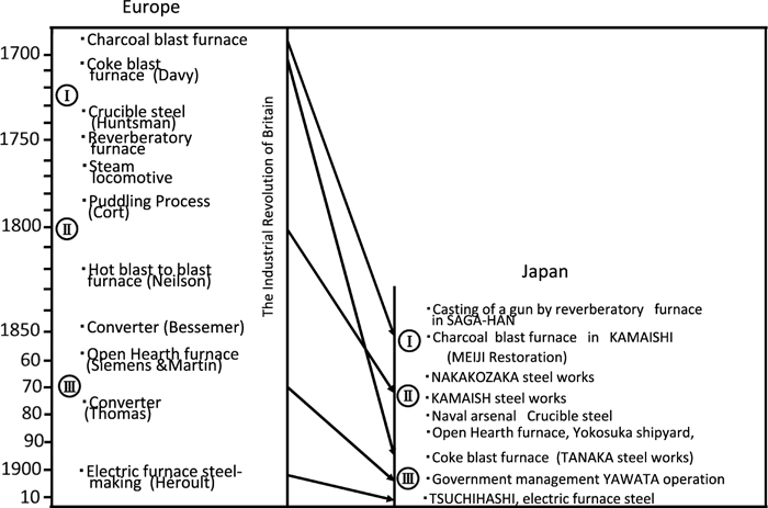
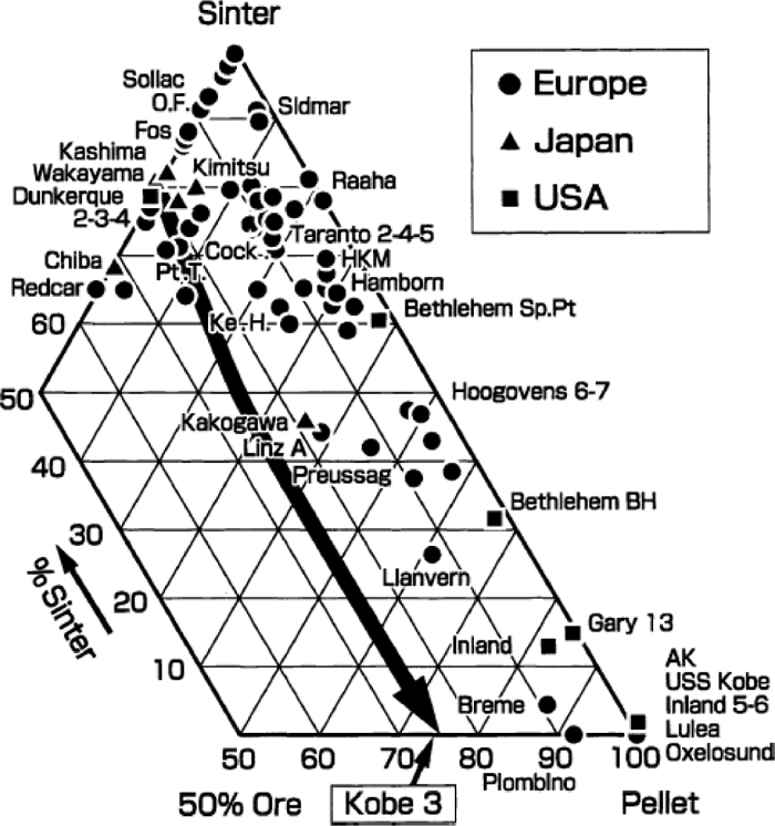

;%0A%09%09%09newWindow.document.open();%0A%09%09%09newWindow.document.write('<img src=%22./Graphics/55_7_tbl_2.jpg%22>');%0A%09%09%09newWindow.document.close();%0A%09%09)
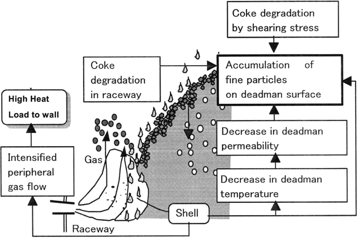
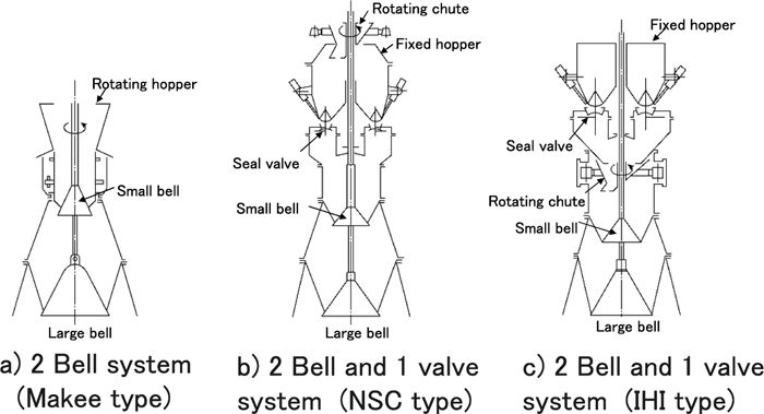
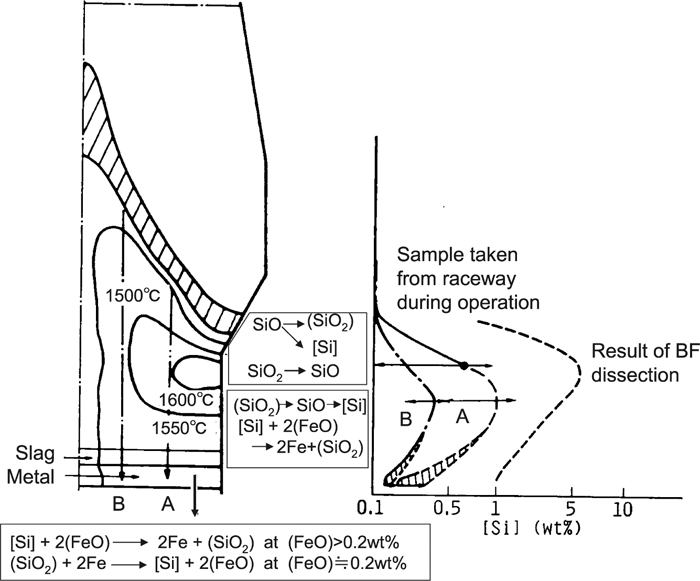
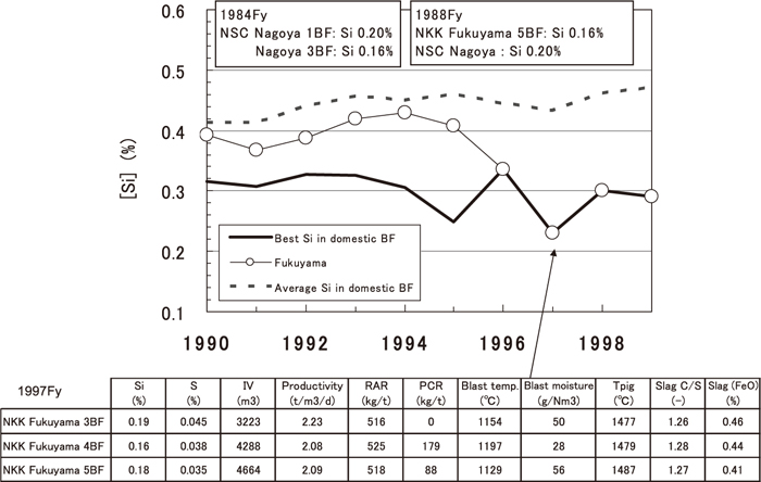

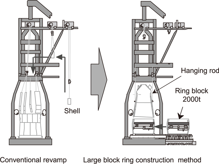

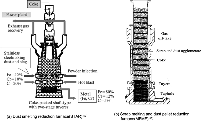
;%0A%09%09%09newWindow.document.open();%0A%09%09%09newWindow.document.write('<img src=%22./Graphics/55_7_tbl_3.jpg%22>');%0A%09%09%09newWindow.document.close();%0A%09%09)