Regular Article
Process Engineering Approach Towards Low Carbon Consumption in Carbon Cycle by Smart Iron Manufacture
2015 Volume 55 Issue 2 Pages 365-372
Details
2015 Volume 55 Issue 2 Pages 365-372
This paper describes a low shaft furnace as a new model with three capabilities for making (1) a “smart iron-manufacturing system” using scrap, (2) “co-production” of electrical power and iron, and (3) a “smart community” of new local adhesion, promotion of industry, and local supply and local consumption into a process which can respond to local demand. In this study, by the “Iron Technology and History Forum”, the iron-manufacturing experimental results using a low shaft furnace were analyzed by chemical reaction engineering, and it is presumed that transient response control of the heating rate and a partial pressure rise of CO in a low shaft furnace were key factors controlling slag and metal components.
Consequent to the developments of the 20th century, the trend of the world iron industry can be summarized by the following five points. The first point is that the benefit of Japan’s iron-manufacturing materials monopoly in Asia is fading due to the rise of steel production in developing countries, especially in Asia. Furthermore, “global resource distribution” on a terrestrial scale is expected due especially to Brazil, which entered the growth track and which will expand its growth zone in the future. It is accompanied by the “co-production” of iron and electric power as the 2nd point, and the production of the blast furnace scale together with expansion of this growth zone as the 3rd point. The 4th point is that “quality improvement of the form of iron supply” of the advanced nations which can enjoy the geographical advantage of resources, such as granular iron production in North America or iron storage in Europe, is accelerating. The 5th is that the advanced nations of Europe and North America are developing “global research-and-development activity” which may hopefully unify the earth. As a result, an alternative theory for a blast furnace method with a new iron-manufacturing process is reaching complete harmonization and these two ways have been changing as the centuries also change.1,2,3)
Since the quality of raw materials can be downshifted, a low shaft furnace seems to be one of the countermeasures for three breakthrough points of (1) the “co-production” of electric power, (2) the “smart iron-manufacturing system” using scrap, and (3) three conditions of the new model (smart community) of new local adhesion, promotion of industry, and local supply and local consumption in the process.
This time, in the iron technology and history forum, the iron-manufacturing experimental results using a low shaft furnace were analyzed by chemical reaction engineering, and it aimed at searching for the seeds of a new iron-manufacturing process technology by clarifying the factors of iron and steel generation with a low shaft furnace.
Figure 1 shows the dimensions of the low shaft furnace. The inner volume of a furnace is 0.08 m3 with one tuyere (a steel pipe of 30 mm in diameter with 30°downward angle) installed and operated in a cold blast. Thirty charges made of 1 kg of lump ore (%t-Fe:68.9), 1.5 kg of charcoal (%C:91.4) were carried out, and the product was made from blow-in in three hours, and steel of 12.8 kg (61.8% of iron yield) was obtained. Moreover, there are only three measurement ends, a blower, a valve travel, and the temperature measurement inserted from a furnace wall by manual operation. In particular, a level change in the height direction of the temperature measurement in a furnace was made based on an observation of the furnace condition.

Structure of experimental low shaft furnace.
Iron-manufacturing operation of the conventional low height furnace is generally classified into the following the four stages.4) The 1st stage is that it is easy to promote a reduction reaction in low melting by charging iron sand, and burning charcoal, and producing slag and metal. In that stage, a furnace is heated up by the exothermic reaction of charcoal combustion. The 2nd stage is that the furnace temperature is raised further, so not only slag but pig iron can also be made. The 3rd stage is that, as the ratio of iron sand is increased gradually, a kind of steel will be made, the furnace condition will become active and a highly bright yellow flame will shine. And while a furnace is gradually eroded, steel lumps grow. The 4th stage is that although the charge of iron sand is increased further and steel increases greatly, if it increases at this time, the furnace wall thickness will become thin, it will become impossible to continue the operation beyond this stage, and it will terminate the operation. The above four stages are made into one generation by one operation.
Figure 2 shows the experimental condition of low height furnace and Table 1 shows components of burden materials, reacted wall and product. The state of this experiment is the same as that of the above in general, and this operation record and analysis research also followed the above-mentioned classification.

Blast condition and charging result of low height furnace.
;%0A%09%09%09newWindow.document.open();%0A%09%09%09newWindow.document.write('<img src=%22./Graphics/55_365_tbl_1.jpg%22>');%0A%09%09%09newWindow.document.close();%0A%09%09)
|
Figure 3 shows change of the temperature distribution in a low height furnace. The temperature in a furnace is decreasing as the stage proceeds. This is assumed to be related to advance direct reduction with the rise in heat in a furnace and discharged FeO slag from iron ore at the beginning as shown in the operation transition (Fig. 2), shifting to the generation of steel. In addition, a feature is that the temperature gradient of the height direction is almost the same through the four stages, as it is the result of a slight change of the rate of gas utilization described in the following section, 2.4.

Change of the temperature distribution in low height furnace.
Table 2 shows the mass balance of a low height furnace. As the amount of actual hot metal is 12.8 kg compared to the calculated amount of hot metal 20.7 kg, the yield of iron is 61.8% and the remaining 38.2% is presupposed to be discharged as FeO slag.
| Operational term | ① Komori 09:00–09:51 | ② Komori Tsugi 09:52–11:04 | ③ Nobori 11:05–11:39 | ④ Kudari 11:40–12:12 | |
|---|---|---|---|---|---|
| Charging Condition | |||||
| Coal rate | (kg/kg-HM) | 2.177 | 2.177 | 2.177 | 2.177 |
| Ore rate | (kg/kg-HM) | 1.451 | 1.451 | 1.451 | 1.451 |
| Heat transfer | |||||
| Furnace height | (cm) | 130 | 130 | 130 | 130 |
| Top gas temperature | (°C) | 512 | 512 | 430 | 157 |
| Top solid temperature | (°C) | 50 | 50 | 50 | 50 |
| Reserve temperature | (°C) | 1770 | 1760 | 1455 | 435 |
| Heat fux ratio | (–) | 0.73 | 0.73 | 0.73 | 0.72 |
| Top gas rate | (Nm3/kg-HM) | 3.776 | 3.784 | 3.787 | 3.823 |
| Oxygen balance | |||||
| blast gas rate | (Nm3/kg-HM) | 0.079 | 0.089 | 0.092 | 0.139 |
| Blast volume (cal.) | (Nm3/min) | 0.009 | 0.010 | 0.011 | 0.016 |
| (cc/min) | 9017 | 10199 | 10569 | 15943 | |
| Blast volume (act.) | (cc/min) | 9077 | 10411 | 10667 | 15541 |
| Oxygen in blast | (kg/kg-HM) | 0.024 | 0.027 | 0.028 | 0.042 |
| Total oxygen | (kg/kg-HM) | 2.698 | 2.701 | 2.702 | 2.716 |
| Carbon balance | |||||
| ηCO | (%) | 1.7 | 1.8 | 1.9 | 2.4 |
| Solution loss C | (kg/kg-HM) | 1.972 | 1.970 | 1.969 | 1.958 |
| Direct reduction ratio | (%) | 99.1 | 99.0 | 99.0 | 98.4 |
| Indirec reducition | (%) | 0.9 | 1.0 | 1.0 | 1.6 |
By considering that the temperature distribution in a furnace over four stages (Fig. 2) was the counter-current flow moving bed, the heat flux ratio was calculated by disregarding the temperature change in the heat loss from a wall, and changes in particle temperature. About the heat reserving temperature which is needed here, since the temperature in a furnace of 1200°C or more was not able to be measured, the heat reserving temperature was estimated by parameter fitting to make an adjustment between calculated and actual blast volume. As a result, the heat flux ratio can be determined uniquely by top gas volume and the amounts of gasified oxygen can be determined uniquely by the carbon and oxygen balance. Through four stages of a low shaft furnace, as ηco is as low as 2.0%, the molar ratio of gasification oxygen to the gasification carbon in a furnace is about 1.0, and it turns out that reduction in a furnace is dominated by direct (smelt) reduction with an endothermic reaction.
In stage four, although ηco slightly rises to 2.4%, this tendency corresponds with the report of Nagata calculation on the exhaust gas of the steel association restoration Tatara operation5,6,7,8,9) with 12.5% on the fourth stage of the second operation and 11.7% on second stage of the third operation.
Figure 4 shows the diagnostics on the low height furnace with an unsteady-state by components. Especially on the fundamental requirements for the traceability of tapping and de-slagging, individual components must be carried out as a process index, being able to carry out tracking (pursuit), tracing back the record further, and being able to carry out the trace back (retroactivity). And also it must satisfy the mass balance and be able to express the reaction temperature through the distribution ratio of a slag metal for that purpose.

Diagnostics on low height furnace with unsteady-state by components.
In this experiment, as Hercynite (FeO·Al2O3)10) has not been detected, so the material balance is based on the conservation of the mass of Al2O3. And also the experimental condition is made by cold blast, so the assumption of Si–SiO2 equilibrium state is induced and the results are checked by a maximum- probability estimation11) whether it has good rationality with the example of other cases.
Figure 5 shows the methodology of traceability of slag components as a process indicator. By setting the amount of furnace wall reactions by wall erosion or adhesion of a furnace wall to unknown variable (x) and the amount of generation of slag to unknown variable (y) for the components distribution between slag and metals, the simultaneous equations12,13) with the conservation of mass of Al2O3 of each component within the dotted line were described as follows.
| (1) |
ai: weight percentage of i-component in furnace wall (%)
bi: weight percentage of i-component in formed slag (%)
ci: difference between discharging rate by metal and burden (kg/kg-hm)
x: reacted wall rate (kg/kg-hm)
y: formed slag rate (kg/kg-hm)
And also, it is recognized that reaction means elution and slag discharging if x,y>0, and also to be adhesion in a furnace, if x,y<0.

Methodology on traceability of slag components as process indicator (w: wall, s: slag, b: burden, m: metal).
Figure 6 shows a comparison of calculated reacted wall and formed slag and total flux by Eq. (1). As three components of SiO2, CaO, and V, which may satisfy the material balance of total flux with the dotted line from the conservation of the mass of Al2O3, Si has the traceability to express the distribution between slag metals components.
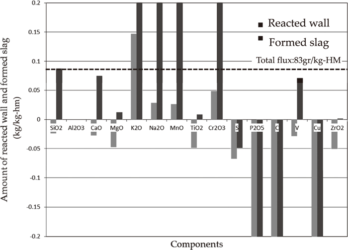
Comparison of calculated reacted wall and formed slag and total flux.
On the distribution reaction of Si to slag and a metal:
| (2) |
| (3) |
| (4) |
Furthermore, as the carbon content is sufficient in the lower furnace part and carbon activity can be set with 1, an equilibrium distribution ratio is expressed as a function of temperature and CO partial pressure and oxygen partial pressure is denoted by the following formula.
| (5) |
| (6) |
| (7) |
On the other hand, as the charcoal ash composition has acid side, so it is newly approximated and defined by (8) from the experimental value on the low basicity of Taylor and others.17) In addition, as the SiO2 molar-fraction NSiO2, the formula of Tamura’s.18)
| (8) |
Figure 7 shows the estimation of reaction temperature from the relationship C% and Si% which were obtained from SiO2–Si equilibrium distribution and temperature as a parameter. The reaction temperature of this experimental result (%Si: 0.03, %C: 0.15) was presumed to be 1143°C. In addition, the result of the Society for Preservation of Japanese Art Swords, Tonami, Ataidani and Nagata20) was plotted together as the example of a low furnace.19)

Estimation of reaction temperature from relationship %C and %Si under assumption of SiO2–Si Equilibrium.
In the case of out flow of iron by Nagata (%Si: 0.029, %C: 2.73), the reaction temperature was presumed to be 1175°C. As this estimated temperature is close to the average value of 1204°C of the bottom temperature (1048°C) and tuyere temperature (1359°C), so the temperature presumption from SiO2–Si equilibrium distribution proved to be appropriate.
3.3. Presumption of Amount of Smelting Reduction ReactionsFigure 8 shows an estimation of the smelt reduction carbon rate from a phase diagram of the Fe2SiO4–TiO2 system. In this figure, the slag components are approximated to the ternary system of FeO–SiO2–TiO221) (%FeO: 36.2, %SiO2: 23.6, %TiO2: 40.2) and it was displayed as point A. The melting point of A, 1273°C, deviated greatly from the above-mentioned reaction temperature of 1143°C.

Estimation of smelt reduction carbon rate from phase diagram of Fe2SiO4–TiO2 system.
Since the estimated temperature of 1143°C is close to the eutectic temperature of 1134°C of Fe2SiO4 (Fayalite) and Fe2TiO4 (Ulvospinel), it is estimated that this eutectic composition (point B) is that of primary slag (%FeO: 66.9, %SiO2: 23.6, %TiO2: 9.5). Moreover, it is believed22) that FeO in this primary slag carried out the smelting reduction reaction, and the TiO2 concentration in slag rose as a result.
The upper row of Fig. 8 shows the carbon-content change consumed by this smelting reduction reaction. The smelting reduction carbon content is equivalent to 0.40%C. However, since the amount of solution loss carbon in the whole system is 1.97 kg-C/kg-HM in the material balance of Table 1, the rate of the smelting reduction reaction to the direct reduction reaction is low.
3.4. Presumption of Carbon ActivityIn order to enlarge the low height furnace volume and the continuous process flow and the outflow of molten iron must be focused on.
Figure 9 shows the approximate linear carbon-activity (ac) in the γ-region of Fe–C system. In this figure, the relation of the reaction temperature and the carbon content which were obtained from SiO2–Si equilibrium partition, corresponded with the carbon activity.23)

Linearly approximated carbon-activity in γ-region of Fe–C system.
Although the outflow of molten iron by the Japanese fine arts sword preservation association, Tonami, Ataidani are shown within the dashed line and distributed over the large area of approximately 1.78–3.95%C carbon content, it has converged mostly with the carbon activity of 0.7 and attracts attention. Therefore, it was suggested that the lower section in a low shaft furnace is affected by the reactivity of charcoal.
Figure 10 shows the methodology of charcoal performance in the low height furnace. In ancient times, charcoal for general use was divided into hard charcoal burned by high temperature (about 1000°C), soft black coal burned with low temperature (400–800°C), and used charcoal cinders, it has been reported that the charcoal used in a low height furnace in ancient times differed from these typical charcoal.
Methodology of char coal performance in low height furnace.
The charcoal which is used for iron refinement in a low furnace is called “big charcoal” and the charcoal of forging is called “small charcoal” from ancient times. The big charcoal has been manufactured by a method similar to black coal, the temperature to burn is lower than black coal in order to make half steamed area inside the charcoal particles and let the quality as charcoal be inferior.
In particular, low fixed carbon content (60% or less) and high volatile matter content (30% or more) is preferred for big charcoal. Moreover, according to the book of “Tetsuzan secret”, pine, chestnut, podocarp and beech make big charcoal and are good for iron-making and carpinus, magnolia Kobus and cherry trees are bad, and chinquapin, lagerstroemia indica make the worst. In addition, quercus acutissima, Japanese oak (Quercoideae) and miscellaneous trees are also used often. The use of pine, chestnut, horse chestnut, and Japan cedar are the very very best for small charcoal, but carpinus, chinquapin, podocarp, Quercus and aquifoliaceae are not so good.24)
On the other hand, it is reported that iron could be made even if it was not from charcoal. Then, in the case of firewood, however dry it may be, it is thought that the reduction atmosphere in a furnace was brought with juice coming out oozily. What is called “hydrogen reduction” was made in this way.25)
4.2. Difference in Amount of Initial Carburizing by Reactivity of CharcoalCharcoal reactivity is measured by putting a sample into a cylindrical container made from quartz, and is evaluated considering the reaction rate (CO/(CO+2CO2): Rco) by the conversion ratio of CO2 to CO under 950°C and a CO2 atmosphere (30 min).26) The reaction rate of charcoal of 46–73% is very high with compared to coke of 7%.
The relation between the reactivity of charcoal and the Boudouard reaction is expressed by the following formula.
| (9) |
The carbon [%C]γ dissolved in gamma-iron is produced by the decomposition reaction of CO.27)
| (10) |
| (11) |
| (12) |
Therefore, [%C]γ, sat. can be presumed if the charcoal reaction rate Rco is given. Figure 11 shows the effect of charcoal reactivity on the %C of the γ-region of the Fe–C system. In this experiment, as Japanese oak black coal is used, [%C]γ is presumed to be about 0.08%.
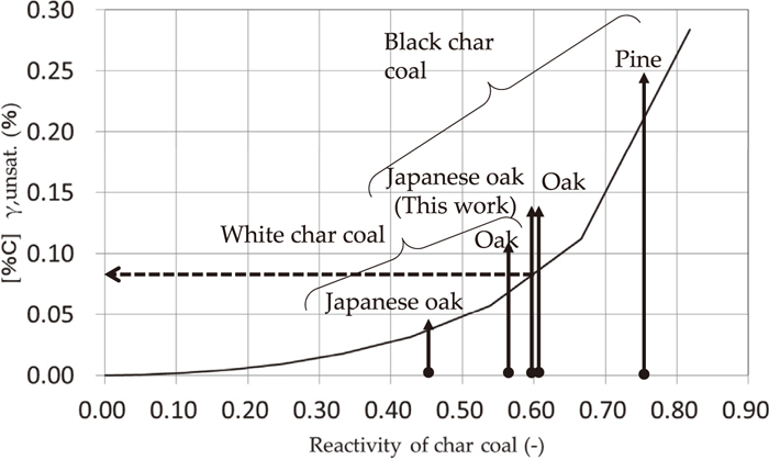
Effect of char coal reactivity on %C of γ-region of Fe–C system.
Figure 12 shows the starting point of gas carburization on %C of the γ-region of the Fe–C system. According to the book “Tetsuzan Secretary”, pine, chestnut, podocarp and beech make good big charcoal, this means the charcoal reaction rate (Rco) is 0.55 or more and ηCO is equivalent to 0.30 or less according to Eq. (8) and this ηCO is equivalent to point G' in Fig. 12.
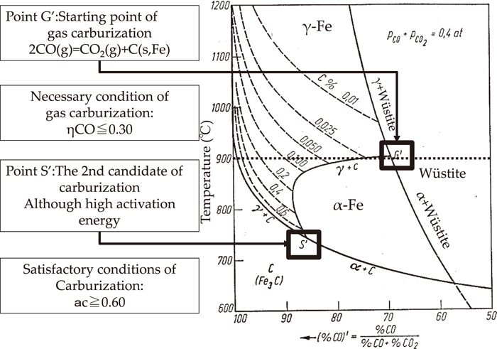
Starting point of gas carburization on %C of γ-region of Fe–C system.
On the other hand, presuming the carbon activity of Fig. 9, the outflow of molten iron has converged the carbon activity of 0.7 approximately, and this is equivalent to point S' in Fig. 12.
Therefore, it is estimated that ηCO is more than 0.30 as a necessary condition of iron manufacturing in a low furnace and it is believed that carbon activity (ac) is more than 0.60 as a sufficient condition for the high activation energy of a carburizing reaction.
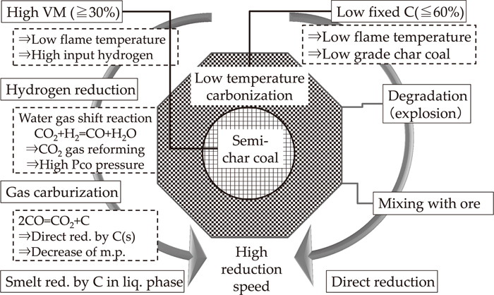
4.4. Predominant Factors of Metal Components in Low Shaft FurnaceFigure 13 shows the key map of the watershed divide of iron and steel in a low height furnace. In the microscopic observation of the refinement slag in this experiment, since “the ferrite single phase” and “metallic iron grains” are observed, the direct reduction from “the iron-point” as a starting point with reduction proceeds past G' point of a carburizing path.

Watershed divide of iron and steel on low height furnace.
Although the amount of carburizing in γiron is about 0.08%, since Japanese oak black coal that is used in this experiment has low reactivity, CO partial pressure could not be increased to the extent that the heating rate increases, and it is presumed that the final carbon content was only 0.15%.
It seems that the transient response control of this heating rate and the CO partial pressure rise are predominant factors of iron and steel generation in a low shaft furnace.
Figure 14 shows the synthesiology28) of changes in the iron making process. It seems that the low shaft furnace accompanied specialization and enlargement differentiated into the two poles of the blast furnace method and the new iron making method while meeting the needs of the time. However, the components control technology of low shaft furnace is attracting the needs in and outside the country.

Synthesiology of changes of a iron making process.
The technology and the history forum in this paper and “while studying historically and scientifically the technology and history of the method of iron making in Japanese ancient times, and the processing method and the objective of the elucidation of an academic subject, The iron-manufacturing experimental result in a low shaft furnace was analyzed by chemical reaction engineering for the purpose of searching for the seeds of new steel technology”, and the following conclusions were obtained.
(1) Although the reaction between the slag and the metal is not expected to be in an equilibrium state in furnace hearth, the distribution equilibrium state was controlled by the oxygen partial pressure and the temperature which are specified by the Boudouard reaction. It is assumed that an equilibrium distribution ratio to metal and slag was determined by the oxygen partial pressure specified by carbon gasification.
(2) It is estimated that ηCO is more than 0.30 as a necessary condition for iron manufacturing in a low furnace and it is believed that carbon activity (ac) is more than 0.60 as a sufficient condition for the high activation energy of a carburizing reaction.
(3) It seems that transient response control of this heating rate and the CO partial pressure rise are predominant factors of iron and steel generation in a low shaft furnace.