Regular Article
Simulation Research of Flow Field in Continuous Casting Mold with Vertical Electromagnetic Brake
2015 Volume 55 Issue 4 Pages 814-820
Details
2015 Volume 55 Issue 4 Pages 814-820
The narrow face of continuous casting mold is the first impact region of the jet from the submerged entry nozzle (SEN), and against the characteristic a new pattern of electromagnetic brake device is proposed, which is called Vertical Electromagnetic Brake (V-EMBr) and its magnetic poles can cover the free surface and the frontier region of solidified shell. The effect laws of magnetic flux density, casting speed and the submergence depth of the SEN on flow field in mold with V-EMBr are investigated by numerical simulation method. The results show that with the magnetic flux density increasing, inhibitory effect of electromagnetic force on molten steel from SEN is increased gradually, impact strength of molten steel stream on narrow face is weakened gradually, the vortex center of lower recirculation zone is moved up gradually and the flow velocity of free surface is decreased gradually. These can reduce the fluctuations of free surface and chance of slag effectively, suppress impinging depth of molten steel in lower recirculation zone and float air bubbles and inclusions beneficially. In addition, the V-EMBr technology can also be applied to different casting speed and different submergence depth of the SEN in continuous casting process. The significantly metallurgical effects and flexibility of application range which are generated by V-EMBr is in line with the original intention of the V-EMBr design.
During the continuous casting process, enhancing the casting speed is a key factor to improve productivity of slab. But this will be accompanied by the generation of some negative factors, such as slag, breakout and unfavorable floating of inclusions and other shortcomings. These shortcomings not only reduce the quality of the slab but also increase the risk of continuous casting process. To solve the problems, the electromagnetic brake technology has come into being. The electromagnetic brake technology began in the early 1980 s, it had undergone the Regional-type Electromagnetic Brake,1) the EMBr-Ruler2) and the FC-Mold.3) In recent years, the application and the research of the electromagnetic brake technology have been extensively development and achieved the good metallurgical results.4,5,6,7,8,9,10,11,12,13)
The common feature of the EMBr-Ruler and the FC-Mold is that the magnetic poles are arranged horizontally in the whole width direction of the mold, and it is shown in Fig. 1. The magnetic poles of the EMBr-Ruler combined with an iron core which surrounds around the mold constitute a magnetic closed loop, and while the upper and lower magnetic pole of the FC-Mold are connected to constitute a magnetic closed loop.14,15) However, in fact the first impact region of molten steel stream from the SEN in mold is the narrow face region. On one hand, this may cause breakout for unevenness or remelting of solidified shell, and also increase the impact depth of the high temperature molten steel. On the other hand, the high temperature molten steel impacts narrow face to form upper regurgitation, which exacerbates fluctuations and flow velocity of the meniscus near the narrow face of mold and leads slag easily. Therefore, controlling the narrow face of mold which molten steel stream from the SEN impacts firstly is the key link to inhibit and reduce the fluctuations and slag of the meniscus, subcutaneous inclusions and bubbles and other defects. Accordingly, a new method for the electromagnetic brake is proposed in this paper,16) which is called Vertical Electromagnetic Brake (V-EMBr), the structure is shown in Fig. 2. Along the height direction and near the narrow face of mold, two pairs of poles of V-EMBr are arranged vertically and cover the free surface of molten steel and the frontier region of solidified shell, which is the first impact region of the jet from the SEN. Using the vertical magnetic poles control both the meniscus region near the narrow face of mold and the first impact region, this is in order to inhibit surface fluctuations and slag of mold and the impact depth of bubbles and inclusions, which improve the quality of the slab. In this paper, the numerical simulation method is used to calculate the flow field in mold with V-EMBr, and the effect of metallurgy is studied.

EMBr-Ruler and FC-Mold.

Vertical Electromagnetic Brake (V-EMBr).
The flow of molten steel in mold with V-EMBr is a steady-state. The effect of slow flow of molten steel on distribution of magnetic field is ignored, and the volume density of the free charge is also ignored. The electromagnetic properties of molten steel are considered to be uniform and isotropic. The electric potential equation is solved to get the current density.17)
The equation of induced current density J
| (1) |
| (2) |
| (3) |
| (4) |
| (5) |
The three dimensional flow field in mold with V-EMBr is calculated by some assumptions as follows. The interface between molten steel and mold is no-slip boundary, the flow velocity of molten steel at the wall is zero. The flow of molten steel is single-phase flow, and physical parameters are constant. The impact of mold taper, solidified strand shell and vibration on the flow of molten steel are ignored. The liquid surface of molten steel is flat, the impact of mold powder is not considered. The governing equations of three-dimensional flow field in mold with V-EMBr are shown below.
The continuity equation
| (6) |
| (7) |
k equation
| (8) |
| (9) |
| (10) |
| (11) |
Since the slab is with symmetry, half and quarter volume of the slab are taken to calculate magnetic field and flow field respectively. The boundary conditions are set as follows. The components of velocity and current density which are perpendicular to the wall are zero, and the components which are parallel to the mold wall are used no-slip boundary condition. The gradient of each variable on free surface of molten steel is zero along the normal direction. The gradient of each variable on symmetry plane is zero along the normal direction.17) The inlet is defined as the inlet of the SEN, the inlet velocity is determined according to the casting speed, Kinlet=0.01 Uinlet2, εinlet=Kinlet3/2(d0/2), Uinlet is the inlet velocity, d0 is the inlet diameter. The outlet is defined as the bottom of the computational domain, and the normal derivative of each variable is zero along this section. The mainly parameters for calculating which are provided by a domestic steel mill are shown in Table 1.
| Mold width | 1450 mm |
| Mold thickness | 230 mm |
| submergence depth of SEN | 170 mm, 200 mm, 220 mm |
| SEN port angle | –15° |
| Molten steel density | 7020 kg/m3 |
| Molten steel viscosity | 6.2×10⁻³ Pa·s |
| Molten steel electric conductivity | 7.14×10⁵ S/m |
| Electric current | 680 A, 850 A, 1020 A |
| Casting speed | 1.4 m/min, 1.6 m/min, 1.8 m/min |
| Diameter of the particle | 100 μm |
The calculation is divided into two steps. Firstly, the three-dimensional model of magnetic field in mold with V-EMBr is established by ANSYS software and then it is solved to obtain the distribution of magnetic flux density. Secondly, the three-dimensional model of flow field in mold with V-EMBr is established and the MHD module19) is called by FLUENT software, the result of magnetic field in firstly step is the load for coupling calculation of flow field and magnetic field. The discrete phase model20) is used to solve the trajectories of inclusion particles. The relative residuals of mass source term of continuity equation and each velocity component are set by SIMPLE method, when the iteration is the convergence criteria 0.0001, the procedure exits automatically and then the three-dimensional distribution of flow field in mold with V-EMBr are obtained.
When the casting speed is 1.6 m/min, the submergence depth of the SEN is 170 mm and electric current intensity is 680 A, 850 A, 1020 A respectively, the distribution of flow field of molten steel in mold and flow velocity of free surface are shown in Figs. 3 and 4. Figure 5 shows the movement trajectories of inclusion particles in mold. The magnetic flux density is marked by average value of magnetic flux density Bave in covered region.

Flow field in mold with different magnetic flux density (a) Bave=0 T, (b) Bave =0.24 T, (c) Bave=0.30 T and (d) Bave=0.36 T.

The effect of magnetic flux density on flow velocity of free surface in mold.
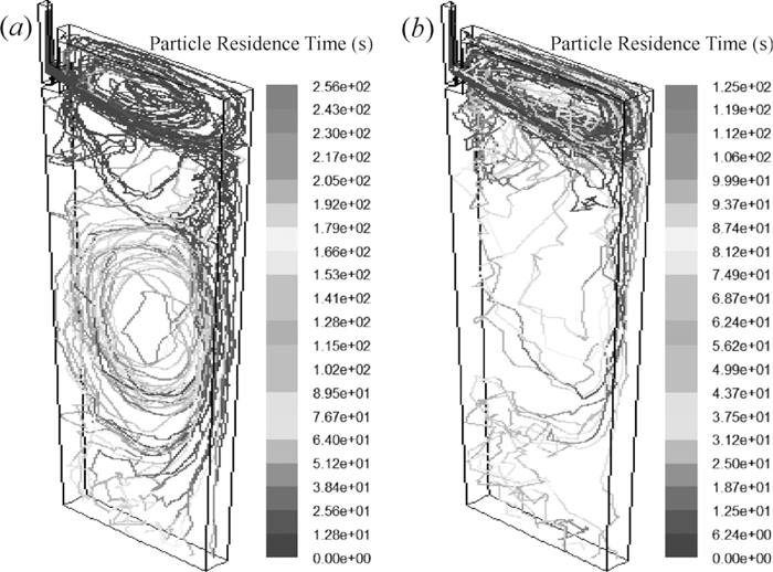
The movement trajectories in mold of inclusion particles with (a) no EMBr and (b) V-EMBr.
The calculation results show that the strength of steel flow is weaken, the vortex center in lower recirculation zone is moved up (Figs. 3(b), 3(c) and 3(d)) and flow velocity of the free surface is decreased (Fig. 4) gradually with the magnetic flux density increasing after applying V-EMBr. These show that with the magnetic flux density increasing, the inhibitory effect of electromagnetic force on steel mainstream is increased gradually, and the speed and strength of molten steel jet from the SEN is decreased gradually. When Bave is 0.3 T, the impinging depth in lower recirculation zone is shallower and the flow velocity of molten steel and flow velocity of the free surface in mold are reduced significantly (Figs. 3, 4). And the upward movement portion of 100 inclusion particles is increased obviously and the downward movement portion of the 100 inclusion particles is reduced in mold (Fig. 5). So using design scheme of magnetic field of V-EMBr can control the flow velocity in mold effectively, stable the fluctuations of free surface effectively, reduce the chance of slag and suppress the impact depth of molten steel simultaneously to promote floating bubbles and inclusions.
3.2. The Impact of Casting Speed on Flow Field of Molten Steel in MoldWhen the Bave is 0.3 T and the submergence depth of the SEN is 170 mm, the flow process of molten steel in mold without and with V-EMBr is simulated with different casting speed. The vector of flow velocity is shown in Figs. 6 and 7. The counter of flow velocity of free surface is shown in Figs. 8 and 9. The vector of flow velocity and the counter of turbulent kinetic energy of narrow face are shown in Figs. 10 and 11. With the casting speed increasing, the entire flow of molten steel in mold is enhanced, the vortex center in lower recirculation zone is moved down, the flow velocity of free surface is increased, the velocity and impact of steel mainstream from the SEN is enhanced and the turbulent kinetic energy of narrow face is increased (Figs. 6, 8, 10). These are likely to cause slag, nonmetallic inclusions and bubbles involving and steel breakout. After applying V-EMBr with different casting speed in continuous casting process, the flow velocity in upper recirculation zone is slow down, the vortex center in lower recirculation zone is moved up obviously and the impact of steel mainstream on narrow face is weaken (Fig. 7). The flow velocity of free surface is reduced significantly (Fig. 9). Especially, the impingement point of steel jet and flow field of its surrounding area show the irregular divergence flow without EMBr (Fig. 10). After applying V-EMBr technology, the divergence situation of irregular flow of jet impingement point and its surrounding area disappear obviously, and form the regular and ordered vertical flow which has upward and downward flow (Fig. 11), so when the casting speed is increased resulting the enhanced velocity of steel jet, the V-EMBr can weaken the impact of steel jet on narrow face and reduce the chance of breakout. Therefore, it is sure that the V-EMBr technology can play a good braking effect with different casting speed in continuous casting process.

Flow field in mold without EMBr when casting speed is (a) 1.4 m/min, (b) 1.6 m/min and (c) 1.8 m/min.

Flow field in mold with V-EMBr when casting speed is (a) 1.4 m/min, (b) 1.6 m/min and (c) 1.8 m/min.

The flow velocity of free surface in mold without EMBr when casting speed is (a) 1.4 m/min, (b) 1.6 m/min and (c) 1.8 m/min.

The flow velocity of free surface in mold with V-EMBr when casting speed is (a) 1.4 m/min, (b) 1.6 m/min and (c) 1.8 m/min.

The vector of flow velocity and contour of turbulent kinetic energy of narrow face without EMBr when casting speed is (a) 1.4 m/min, (b) 1.6 m/min and (c) 1.8 m/min.

The vector of flow velocity and contour of turbulent kinetic energy of narrow face with V-EMBr when casting speed is (a) 1.4 m/min, (b) 1.6 m/min and (c) 1.8 m/min.
In summary, the V-EMBr can be suitable used for different casting speed effectively, help to avoid surface slag and steel breakout, and promote inclusion floating. And it contributes to suppress slab defects caused by casting speed increasing.
3.3. The Impact of Depth of Submerged Entry Nozzle on Flow Field of Molten Steel in MoldWhen the Bave is 0.3 T and the casting speed is 1.6 m/min, the flow process of molten steel in mold without and with V-EMBr is simulated with different submergence depth of the SEN. The vector of flow velocity is shown in Figs. 12 and 13. The counter of flow velocity of free surface is shown in Figs. 14 and 15. The vector of flow velocity and the counter of turbulent kinetic energy of narrow face are shown in Figs. 16 and 17. With the submergence depth of the SEN increasing, the flow velocity in upper recirculation zone is gradually slow and the vortex center in lower recirculation zone is moved down (Fig. 12). The flow velocity of free surface is slightly smaller, this is due to increased scope of the upper recirculation zone, and the distance of swirling flow of molten steel increasing makes the dissipation of steel stream increasing (Fig. 14). And the impinging point of slab narrow face which is impacted by steel jet is moved down, but speed and impact strength is not diminished (Fig. 16). The flow velocity of free surface slowing down can help to reduce fluctuations of free surface and mold powder involvement, but the vortex center of lower recirculation zone moving down makes the impinging depth of lower recirculation zone become deeper, this is not conducive to separation and removal of non-metallic inclusions and bubbles and the growth of initial solidification shell.

Flow field in mold without EMBr when submergence depth of the SEN is (a) 170 mm, (b) 200 mm and (c) 220 mm.

Flow field in mold with V-EMBr when submergence depth of the SEN is (a) 170 mm, (b) 200 mm and (c) 220 mm.

The flow velocity of free surface in mold without EMBr when submergence depth of the SEN is (a) 170 mm, (b) 200 mm and (c) 220 mm.

The flow velocity of free surface in mold with V-EMBr when submergence depth of the SEN is (a) 170 mm,(b) 200 mm and (c) 220 mm.

The vector of flow velocity and contour of turbulent kinetic energy of narrow face without EMBr when submergence depth of the SEN is (a) 170 mm, (b) 200 mm and (c) 220 mm.

The vector of flow velocity and contour of turbulent kinetic energy of narrow face with V-EMBr when submergence depth of the SEN is (a) 170 mm, (b) 200 mm and (c) 220 mm.
After applying V-EMBr technology, flow velocity in upper recirculation zone is reduced significantly, impact strength of steel jet on narrow face is weakened and the vortex center in lower recirculation zone is moved up obviously (Fig. 13). The flow velocity of free surface in mold is reduced significantly (Fig. 15). Obviously, the divergence of the impact point of jet and irregular flow of its surrounding region is disappeared, and this is replaced by the regular, orderly, up and down flow pattern. The turbulent kinetic energy of slab narrow face is reduced (Fig. 17). These show that the V-EMBr can control high-speed steel mainstream from the SEN effectively, stable fluctuations of free surface in mold and inhibit the impact depth in lower recirculation zone in mold, and the critical region of narrow face is subject to braking effect effectively.
Therefore, applying V-EMBr technology is conducive to avoid slag, prevent leakage, reduce the impact on the initial solidification shell and promote floating and separation of non-metallic inclusions and bubbles with different submergence depth of the SEN. Meanwhile, the position of V-EMBr device is not adjusted with the depth change of the SEN. The V-EMBr can reduce the defects in continuous casting process and be applied for different depth of the SEN in slab continuous casting process.
A new type of electromagnetic brake technology which is presented in this paper is called vertical electromagnetic brake (V-EMBr). After application of the V-EMBr, with the magnetic flux density increasing, the inhibitory effect of steel mainstream from SEN by the electromagnetic force is increased gradually and the impact intensity of steel mainstream on narrow face is weakened gradually. The vortex center of lower recirculation zone is moved up gradually and the flow velocity of free surface of molten steel is decreased gradually. The phenomena can reduce the fluctuations of free surface and the chance of slag and avoid steel leakage effectively, and suppress the impinging depth of molten steel simultaneously which is conducive to floating of bubbles and inclusions, and reach the metallurgical effects of electromagnetic brake. These show that the design of vertical electromagnetic brake is feasible and effective.
The V-EMBr technology can be applied to different casting speed and different submergence depth of SEN in continuous casting process. It can effectively control the meniscus of vicinity of mold narrow face and the impact region of steel mainstream from the SEN. The flow velocity of free surface in mold and turbulent kinetic energy of narrow face are reduced and the divergence situation of irregular flow of jet impingement point and its surrounding area is disappeared obviously. It can also help to suppress the defects of slab caused by increasing of casting speed and submergence depth of the SEN. And the above characteristics meet the design ideas of the V-EMBr.