Regular Article
Development of High Silicon Dual Phase Austempered Ductile Iron
2015 Volume 55 Issue 5 Pages 1106-1113
Details
2015 Volume 55 Issue 5 Pages 1106-1113
This work deals with the feasibility of obtaining Austempered Ductile Iron with Dual Phase structures (DPADI) through heat treatment, starting from different as-cast microstructures. The mechanical properties on these microstructures were evaluated. DPADI microstructures were obtained by adding different tenors of silicon (2.4% to 4.2%) to the melts and keeping the other alloying elements constant. The study focused on the determination of the time required to achieve the percentages of equilibrium phases (ferrite and austenite) at different temperatures in the intercritical temperature interval as a function of the starting as cast microstructure. The results showed that, as the silicon content increases, higher amount of ferrite is present in the as cast structure, and the time required to reach the thermodynamic equilibrium phases in the intercritical temperature interval is markedly reduced. Similarly, for a constant chemical composition, as the intercritical austenitizing temperature increases, the time required to reach the quantities of the equilibrium phases decreases.
Regarding mechanical properties, the tests revealed that, as expected, as intercritical austenitising temperature increases so do tensile strength and hardness due to the higher ausferrite content in the DPADI matrix.
These results indicate that high silicon Ductile Iron (with Si content higher than 3%) with a mostly ferritic microstructure in as cast conditions yields DPADI microstructures able to dispense with prior annealing heat treatments since the time required to reach the phase equilibrium percentages is compatible with the industrial practice and the mechanical properties are similar as compared to DPADI structures deriving from fully ferritic matrices.
In the last years, a new type of ductile iron (DI) called “Dual Phase” or “Dual Phase ADI” (DPADI) was developed. The novelty of this DI is its mixed microstructure, which is composed of different amounts and morphologies of ausferrite (regular ADI microstructure) and free ferrite.1,2,3,4,5,6,7,8,9,10,11,12,13) This new type of DI has awoken technological interest given the improvement in mechanical properties it has achieved in relation to conventional microstructures (ferritic, pearlitic or martensitic). As a consequence, many studies have centered their attention on assessing the mechanical properties of this new type of DI. Aranzabal et al.1) studied Dual Phase DI applied to car suspension parts applications. These authors attained UTS, yield strength and hardness values similar to those found in pearlitic DI, but with ductility comparable to that obtained in ferritic matrices. Additionally, Wade et al.2) and Verdu et al.3) evaluated the mechanical properties of DPADI with ferrite as a majority phase and small percentages of ausferrite encapsulating graphite nodules. Particularly, they found that the presence of 20% ausferrite in the microstructure increases yield stress and tensile strength (approximately 30%) as compared to fully ferritic DI.
Kilicli et al.9) studied the mechanical properties of DPADI austempered at 375°C with different percentages of ferrite and ausferrite in its microstructure. Particularly, samples with 45% ausferrite and 65% ferrite yielded the best combination of strength and ductility. Basso et al.4,5) analyzed the effect of several variables, such as the number and morphology of phases, austempered temperature and cast section size (or solidification rate), among others, on the final microstructure and mechanical properties. The results indicated that as the amount of ausferrite increases, so do tensile strength and yield stress while elongation decreases in all the austempered temperatures analyzed. The best combination of strength and elongation was obtained from samples austempered at 350°C.4) Regarding the influence of section size on mechanical properties, strength and elongation until failure decrease as the size of the piece increases, yield stress remaining unchanged.5) Therefore, these studies have allowed to conclude that DPADI can combine interesting mechanical properties, particularly higher ratios between tensile strength/elongation until failure compared to other conventional matrices.
Different thermal cycles have been used to produce these new combinations of microstructures. One such methodology consists in subjecting a fully ferritic DI (obtained from the annealing heat treatment) with a definite chemical composition to an incomplete austenitising stage at different temperatures within the intercritical temperature interval of the Fe–C–Si equilibrium diagram (see Fig. 1). In this stage, austenite nucleates and grows, and the amount of austenite is a function of the intercritical temperature. This stage is followed by an austempering step which transforms austenite into ausferrite.4,5,6,7,8,9,10) As a result, a matrix with different relative percentages of free ferrite (original phase matrix) and ausferrite is obtained, depending on the intercritical austenitising temperature used. This methodology provides significant advantages over other methods: microstructures with a controlled number of phases are obtained, and thereby varied mechanical properties. Hence it is possible to obtain a precise percentage of phases in the microstructure as a function of the intercritical austenitising temperature.

Representation of Fe–C phase diagram (at 2.5%Si)12.
This paper centers on the production of DPADI structures starting from microstructures with different relative amounts of ferrite and pearlite in as-cast condition (DPADIAC). The alternative of optimizing mechanical properties and economizing methodologies by adjusting the alloy chemical composition was studied. In particular, focus was placed on the feasibility of obtaining DPADI through heat treatments, starting from different as-cast microstructures. These structures were obtained by adding different tenors of silicon (2.4% to 4.2%) to the melts and keeping the equivalent carbon and other alloying elements practically constant. The study centered on determining the time required to reach the equilibrium phase percentage (ferrite and austenite) within the intercritical interval as a function of temperature, according to the as-cast microstructure (or content of silicon in the alloy). The mechanical properties of DPADIAC (obtained from as-cast structures) were evaluated as well, and compared with respect to the mechanical properties of DPADIFM (obtained from fully ferritic matrix).
To analyze the influence of silicon content on the as-cast structures in conjunction with the transformations occurring within the intercritical interval, four DI melts with different silicon content, ranging from 2.4 to 4.2%, were produced. The melts were obtained from a metal casting foundry, using a 500 kg capacity medium frequency induction furnace and regular quality of raw materials. Inoculation and nodulization procedures were carried out using conventional techniques. The melts were alloyed with cooper to improve austemperability, and poured into 25 millimeter thick Y-blocks (ASTM A 395) used to prepare test specimens. The chemical composition of the melts was determined by means of a BAIRD spark emission optic spectrometer. The metallographic sample preparation was conducted using standard techniques. The microstructural characterization was performed by optical microscopy. Metallographic etching was conducted with 2% nital. The nodularity and nodule count values were determined according to ASTM A 247 standard.
2.2. Determination of the Upper and Lower Critical TemperaturesTo study the time required to reach the equilibrium phase percentage (ferrite and austenite) within the intercritical interval as a function of temperature, according to the as-cast microstructure (or silicon content in the alloy), the upper critical temperature (TICupper) and the lower critical temperature (TIClower) were initially determined for the different alloys. The study of the intercritical interval of each alloy involves determining the upper and lower critical temperatures, and the percentages of phases (ferrite and austenite) as a function of the holding temperature within the intercritical interval. The methodology employed to establish the intercritical interval for a specific alloy has been detailed in a previous work,4,5,6) and is herein summarized as follows: several specimens of each melt (12 mm in diameter and 25 mm in length) were firstly subjected to annealing thermal cycles consisting of: a) austenitising at 900°C for 3 hours, b) cooling down to 740°C inside the furnace, c) holding at 740°C for 10 hours, and d) cooling down to room temperature inside the furnace. It is worth pointing out that fully ferritic structures are usually used to determine the upper and lower critical temperatures and the equilibrium phase percentages as a function of the intercritical temperature.
Later, to establish the intercritical interval for each melt after annealing, the samples were subjected to thermal cycles involving austenitising stages ranging from 730°C to 900°C at 10°C steps. Each complete thermal cycle implied holding the sample in the furnace for one hour at a selected austenitising temperature (Tγ). Samples were water quenched after the austenitising step. The resulting microstructures were composed of different amounts of ferrite (original matrix) and martensite (quenched austenite), depending on the selected austenitising temperature. It is worth mentioning that, according to a previous work,6) a holding time of about 30 min is enough to reach the equilibrium phase percentages in the α → γ transformation within the intercritical interval, starting from fully ferritic matrices. The lower critical temperature was defined as the first temperature at which the presence of martensite (austenite before quenching) was noticeable in the microstructure (evidence of start of ferrite into austenite transformation). The upper critical temperature, in turn, was fixed when a matrix with over 98% of martensite had been obtained from samples quenched at such temperature.
The ferritizing treatments as well as all the austenitising steps were carried out in electric furnaces. The micro-constituents were quantified using an optical microscope and Image Pro Plus software. Reported values are the average of at least five determinations. Graphite areas are not included in the percentages of the reported phases.
2.3. Study of Transformation Kinetics within the Intercritical Temperature IntervalThis study aimed to determine the time required to reach the equilibrium phase percentages, called teq, for the different intercritical temperatures, TIC, and the diverse as-cast microstructures arising from the dissimilar chemical composition of the alloy. The thermal cycle used, named TT1, consisted in an intercritical austenitizing stage at different holding times, followed by quenching. Three intercritical austenitising temperatures, TIC, were selected for each melt in order to obtain different microstructures with different number of phases: one mainly ferritic (TIC1), a second one with similar percentages of ferrite and austenite (TIC2) and a third one with austenite as a majority phase (TIC3). Figure 2 depicts the TT1 thermal cycle followed to determinate the equilibrium phase percentages for the three intercritical temperatures (TIC1, TIC2, TIC3) of each melt.

Scheme of the TT1 thermal cycle used to determinate the time necessary to reach the equilibrium phase percentages, teq, for each melt.
Aside from the as-cast specimens, fully ferritic samples (obtained by annealing heat treatment) were exposed to the same thermal cycle. These fully ferritic samples were used as a reference material to determine the equilibrium phase percentages of each temperature in the intercritical temperature interval. Table 1 summarizes the analyzed holding times for each melt. After heat treatment, each sample was characterized and the phases (ferrite and martensite – quenched austenite) were quantified. Finally, the time necessary to reach the thermodynamic equilibrium phases for each as-cast microstructures, teq, was determined. In all the cases, the percentage of equilibrium phases was considered as that obtained from fully ferritic samples.
| time (h) | ||||
|---|---|---|---|---|
| Melt 1 | Melt 2 | Melt 3 | Melt 4 | |
| TIC1 | 22–30 | 15–20 | 2–6 | 2–5 |
| TIC2 | 20–30 | 13–18 | 2–6 | 2–5 |
| TIC3 | 15–21 | 10–18 | 2–4 | 2–4 |
After the time (teq) required for each melt and the intercritical austenitising temperature, TIC, were defined, DPADIAC and DPADIFM microstructures were obtained. The thermal cycle used involves heating at TIC, holding at this temperature during teq, and austempering in a salt bath at 360°C for 60 minutes. The transformation of austenite into ausferrite takes place during this last stage. This thermal cycle is illustrated in Fig. 3.

Thermal cycle used to obtain DPADI structures.
This paper evaluated the mechanical properties of DPADI microstructures obtained from as-cast structures (DPADIAC); while DPADI obtained from fully ferritic matrix (DPADIFM) was also tested for comparison purposes. The aim of these tests was to quantify the influence of the previous microstructure of tensile samples on the mechanical properties of DPADI, particularly, tensile strength, elongation until failure and hardness.
2.5.1. Tensile TestsTensile tests were carried out following the ASTM E8M standard using an INSTRON 8501 universal testing machine. For each of the selected austenitising temperatures, an average of four samples was evaluated.
2.5.2. Hardness TestsHardness tests were performed following the ASTM E 10 standard. An IBERTEST hardness machine, “DU-250” model, was used. Brinell hardness (HBW) was measured using a 2.5 mm tungsten carbide ball and a bench tester with a 187.5 Kg load. The reported values are the average of four determinations.
Table 2 lists the chemical compositions of the four melts analyzed, while Fig. 4 provides the representative microstructures. In all cases, the castings displayed a nodule size 5, nodularity higher than 80%, and a nodule count of about 100 nodules/mm2. In addition, it can be observed that, as expected, when Si content increased, the amount of ferrite in the as-cast microstructure did too.
| Melt | C | Si | Mn | Mg | Cu | S | P | CE |
|---|---|---|---|---|---|---|---|---|
| 1 | 3.32 | 2.40 | 0.37 | 0.064 | 0.64 | 0.017 | 0.027 | 4.1 |
| 2 | 3.36 | 3.13 | 0.32 | 0.050 | 0.65 | 0.025 | 0.030 | 4.4 |
| 3 | 2.81 | 3.54 | 0.36 | 0.064 | 0.64 | 0.024 | 0.029 | 4.0 |
| 4 | 2.64 | 4.20 | 0.35 | 0.062 | 0.62 | 0.021 | 0.033 | 4.0 |

Microstructures in as-cast condition: (a) melt 1, (b) melt 2, (c) melt 3, (d) melt 4.
Table 3 lists the upper and lower critical temperatures for each melt. As postulated in a previous work,8) an increase in the upper and lower critical temperatures was measured as the amount of silicon increase. However, the difference between the lower and upper critical temperatures (intercritical temperature interval amplitude) remained nearly constant (80°C) for all the ductile irons evaluated in this study.
| Melt | 1 | 2 | 3 | 4 |
|---|---|---|---|---|
| TIC upper. (°C) | 840 | 860 | 880 | 900 |
| TIC lower. (°C) | 760 | 770 | 790 | 810 |
The intercritical temperatures analyzed for each melt are listed in Table 4, while Table 5 shows the percentage of phases in as-cast condition and after reaching the thermodynamic equilibrium for the different melts at the intercritical temperatures studied. Also, the time necessary to achieve this thermodynamic equilibrium, teq, is detailed in such table.
| Temperature (°C) | ||||
|---|---|---|---|---|
| Melt 1 | Melt 2 | Melt 3 | Melt 4 | |
| TIC1 | 800 | 800 | 820 | 840 |
| TIC2 | 815 | 830 | 840 | 865 |
| TIC3 | 830 | 850 | 865 | 890 |
| Melt (%Si) | TIC (°C) | As-cast condition | Eq. At TIC temperature | Teq (h) | ||
|---|---|---|---|---|---|---|
| %ferrite | %pearlite | %ferrite | %austenite | |||
| 1 (2.4) | 1-800 | 25 | 75 | 64 | 36 | 30 |
| 2-815 | 23 | 77 | 24 | |||
| 3-830 | 7 | 93 | 15 | |||
| 2 (3.1) | 1-800 | 44 | 56 | 83 | 17 | 30 |
| 2-830 | 26 | 74 | 24 | |||
| 3-850 | – | – | – | |||
| 3 (3.5) | 1-820 | 72 | 28 | 86 | 14 | 2 |
| 2-840 | 41 | 59 | 2 | |||
| 3-865 | 15 | 85 | 2 | |||
| 4 (4.2) | 1-840 | 85 | 15 | 83 | 17 | 2 |
| 01/02/65 | 28 | 72 | 2 | |||
| 3-890 | 8 | 92 | 2 | |||
Based on Table 5, it can be concluded that when the silicon content in the alloy increases, the time required to reach the percentages of the thermodynamic equilibrium phases (teq) at the different intercritical temperatures is reduced. Similarly, for a constant chemical composition, as the intercritical austenitising temperature increases, teq decreases. These results allow to verify that starting from ferritic-pearlitic as cast structures, with pearlite as a majority phase (melts 1 and 2), the time needed to reach the thermodynamic equilibrium is substantially higher than that required when the as cast structure is mostly ferritic (melts 3 and 4). A more detailed work on this subject matter, which is beyond the scope of the present work, should be conducted in order to clarify the characteristics of the metallurgical transformations that take place in the intercritical temperature interval when the starting microstructure is ferritic-pearlitic.
On the other hand, the morphology of the phases changes when the microstructures are obtained from as-cast samples rather than from the traditional fully ferritic matrices. The structures produced at low temperatures in the intercritical interval with low amount of austenite before austempering (< 40%) show austenite nucleation and growth preferentially in last to freeze (LTF) zones and ferrite grain boundaries when they start from a fully ferritic structure.4,5,6) On the other hand, when as-cast structures containing predominantly a pearlitic matrix are used, such as Melt 1 and Melt 2, austenite nucleates and grows mainly in LTF zones (not in ferrite grain boundaries). These differences can be observed when comparing Figs. 5(a) and 5(b). These figures show two metallographic images of Melt 1, obtained after heat treatment TT1, austenitised at 800°C (samples TIC1-800°C), starting from fully ferritic matrix (5a) and samples in as-cast condition (5b). The microstructures have the same equilibrium phase percentages ferrite and martensite (quenched austenite).

Structures of Melt 1, obtained after TT1 heat treatment, austenitised at 800°C (samples TIC1-800°C) starting from: a) a fully ferritic matrix and b) a mostly pearlitic matrix. The structures feature the same equilibrium phases (ferrite and martensite): ~64% ferrite – ~36% martensite.
On the other hand, when the as-cast microstructures contain higher amount of ferrite (Melt 3 and 4), the structures feature the same phase morphologies (see Fig. 6).

Structures of Melt 1, obtained after TT3 heat treatment, austenitised at 830°C (samples TIC3-830°C) starting from: a) a fully ferritic matrix and b) a mostly pearlitic matrix. The structures feature the same equilibrium phases (ferrite and martensite): ~7% ferrite – ~93% martensite.
For structures with a mostly martensitic (austenite after quenching) matrix (>50%), no differences in phase morphologies obtained from as cast and fully ferritic structures were observed. For example, Fig. 7 shows two metallographic images of Melt 3, obtained after the heat treatment TT3 starting from a fully ferritic matrix (6a) and as-cast condition (6b). In both cases, the austenitization temperature was 865°C (samples TIC3-865°C) and the microstructure was composed of ~15% ferrite and ~85% of ausferrite.

Structures of Melt 3, obtained after TT3 heat treatment, austenitised at 865°C (samples TIC3-865°C) starting from: a) a fully ferritic matrix and b) a mostly pearlitic matrix. The structures feature the same equilibrium phases (ferrite and martensite).
As mentioned above, one of the objectives of this work was to study the difference in mechanical properties between DPADI structures obtained from fully ferritic microstructures and from as cast structures. In this study, only tensile and hardness properties were assessed. Melt 3 was selected to undergo the mechanical tests because teq was compatible with the industrial practice. Table 6 lists the intercritical austenitising temperatures and the phase percentages obtained for the different specimens tested.
| TIC (°C) | % Ferrite | % Ausferrite |
|---|---|---|
| 1-820 | 85 | 15 |
| 2-840 | 40 | 60 |
| 3-865 | 15 | 85 |
Figure 8 shows the DPADIAC metallographics obtained after the thermal cycle.

Structures of DPADIAC, melt 3, obtained after thermal cycle: a) TIC1 (austenitising temperature: 820°C); b) TIC2 (austenitising temperature: 840°C); and c) TIC3 (austenitising temperature: 865°C).
Figures 9 and 10 illustrate the tensile strength and the elongation until failure as a function of the austenitising intercritical temperature for DPADI obtained from a fully ferritic matrix (DPADIFM) and as cast condition (DPADIAC). Table 7 provides the hardness values.

Tensile strength as a function of the intercritical austenitising temperature for Dual Phase ADI structures.
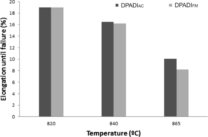
Elongation until failure as a function of the intercritical austenitising temperature for Dual Phase ADI structures.
| Hardness Brinell (HB) | ||
|---|---|---|
| TIC | DPADIFM | DPADIAC |
| 1-820 | 198 | 208 |
| 2-840 | 230 | 256 |
| 3-865 | 278 | 315 |
The values indicate, as expected, that as the intercritical austenitising temperature increases, tensile strength and hardness increase as well given the higher ausferrite content in the matrix. This tendency was noticed in DPADI structures obtained from both fully ferritic matrix and as cast condition. However, for the same intercritical austenitising temperature analyzed (microstructures having the same percentage of ferrite and ausferrite), the tensile strength and hardness values of DPADI obtained starting from a fully ferritic matrix, DPADIFM, were lower than those reported from as cast condition, DPADIAC. This difference became more evident when the amount of ausferrite in the microstructure increased (approximately between 9 and 17%). This allows to conclude that the phase controlling the final properties is the ausferrite in the matrix, which would depend on the austenite formed during austenitization.
The literature has reported that the mechanical properties of the ausferritic phase depend, among other variables, on the grain size and carbon content of the prior austenite.14) A decrement in the austenitic grain size leads to an increase in the mechanical properties of the ausferrite. Furthermore, increasing the intercritical austenitising temperature results in an increase in the carbon content of the austenite, rising ausferrite tensile strength and hardness.
With respect to the structures studied in this project, the austenite grain size which nucleates and grows during the intercritical austenitising temperature starting from as cast condition is expected to be smaller than that achieved from a fully ferritic matrix. Hence the ausferrite formed from the as cast condition yields finer morphology with greater strength and hardness. When austenite nucleates and grows from pearlite, its grain size is smaller if compared to when it nucleates and grows from ferrite. This is due to the fact that pearlite exhibits a higher amount of nucleation sites and carbon content (carbon present in the cementite).14)
Furthermore, increasing intercritical austenitising temperature decreases elongation until failure due to a smaller amount of ferrite in the microstructure.
As it was mentioned in a previous work,13) the use of high silicon DI would be advantageous for components with DPADI structures, since it does not require prior annealing heat treatments. The results reported in the present work allowed to verify that for DI with higher silicon content (melt 3), 2 hours at the intercritical austenitising temperature are enough to reach the equilibrium phase percentage in the production of DPADI structures obtained from as cast condition. Besides, it could minimize dimensional changes and increase machinability in as cast conditions due to the higher amounts of ferrite in the microstructure.
Moreover the mechanical properties of Melt 3 were similar or slightly higher as compared to DPADI structures obtained from fully ferritic matrices.
In order to complete the ultimate objective of this work, i.e., optimizing production technologies and mechanical properties of DPADI, new research is currently underway to shed some light on mechanical properties. In particular, tensile and impact toughness properties of high silicon DPADI structures are being studied.
(1) In this paper the viability of improving mechanical properties and reducing the costs involved in Dual Phase ADI structures production by adjusting the chemical composition of the alloy was studied. The research focus was on evaluating the time required to reach the equilibrium phase percentage, teq, within the intercritical temperature interval as a function of temperature and the as-cast microstructure (or silicon content in the alloy). The results allow to determine that, as the silicon content increases in the alloy, teq is reduced. Similarly, for a constant chemical composition, as the intercritical austenitizing temperature increases teq decreases.
(2) The results indicate that, starting from a pearlitic-ferritic as cast structure with perlite as the majority phase (melts 1 and 2), the time needed to reach the thermodynamic equilibrium phases is substantially greater than that required to reach the thermodynamic equilibrium phases when the as cast structures are mostly ferritic (melts 3 and 4). A more detailed work on this subject matter should be conducted so as to better understand the transformation taking place during austenitization in the intercritical temperature interval.
(3) Small differences in DPADI phase morphologies obtained from as cast and fully ferritic structures were observed. In DPADI structures containing low content of ausferrite (austenite before austempering) in the microstructure (< 40%), it was found that, starting from a fully ferritic structure, austenite nucleates and grows preferentially in LTF zones and ferrite grain boundaries. On the other hand, when the starting microstructure is as-cast, with pearlite as the majority microconstituent, (Melt 1 and Melt 2) austenite nucleates and grows mainly in LTF zones.
(4) Regarding mechanical properties, as expected, the values indicate that as the intercritical austenitising temperature increases, tensile strength and hardness increase as well due to the higher ausferrite content in the matrix. This tendency was observed in DPADI structures obtained from a fully ferritic matrix as well as from as cast condition. However for each intercritical austenitising temperature analyzed (microstructures having the same percentage of ferrite and ausferrite), the tensile strength and hardness of DPADI structures, obtained from the fully ferritic matrix were lower than the values obtained in DPADI starting from as cast condition. Moreover, an increase in the intercritical austenitising temperature resulted in a decrease in the elongation until failure due to a smaller amount of free ferrite in the microstructure.
(5) These results reveal that high silicon DI (with Si content between 3 and 4.2%) with a mostly ferritic microstructure in as cast condition allows to produce DPADI microstructures without the prior annealing heat treatments conducted in a regular DPADI, since the necessary time to reach the equilibrium phases is compatible with the industrial practice and the mechanical properties obtained are similar or slightly higher than those evaluated in DPADI structures obtained from fully ferritic matrices.
The financial support granted by the CONICET, FONCYT and the National University of Mar del Plata is gratefully acknowledged.