Regular Article
Numerical Analysis on Passage and Blockage Behaviors of Fine Particles through an Orifice Consists of Coarse Particles
2015 Volume 55 Issue 6 Pages 1291-1298
Details
2015 Volume 55 Issue 6 Pages 1291-1298
Stable operation under low reducing agent rate condition of blast furnace is necessary to realize to contribute solution of global warming. Under low reducing agent rate operation, large amount of powder materials like fine coke and unburnt pulverize coal generate in the furnace. It is known that the heavy accumulation of these powders in the packed bed of blast furnace deteriorates the permeability, and cause operation trouble in extreme case. Thus it is important to understand the flow and accumulation behaviors of powder in packed bed. This paper discussed the powder motion in the packed bed through numerical simulation under simplified condition. A simplified packing structure, namely an orifice consisting of three spherical particles that touched each other and were in equilateral triangle arrangement, was picked out from the packed bed. The powder trajectories passing through this orifice were tracked by using the discrete element method. The simulation results showed that only a few powder particles initiated the blockage of the particle orifice. Additionally the effects of mechanical properties of the particles on the passage and the blockage behaviors were also revealed.
The Japanese steelmaking industries consumes about 11% of energy consumption in Japan,1) and its 70% is put into the ironmaking processes.2,3,4) Blast furnace is a primary process of the ironmaking system. Carbonaceous materials, like coal and coke, are indispensable in the blast furnace because they play important roles in thermal energy supply, reduction reaction, carburization, and so on. The carbon that is supplied to the ironmaking process is finally released to the environment as carbon dioxide. The reduction of carbon dioxide emission from the ironmaking system is eagerly required. In the low carbon operation of the blast furnace, supplying rates of reducing gas and thermal energy are decreased, and the allowance to the operation fluctuation is deteriorated. To improve the allowance, effective use of whole volume of the blast furnace as the reaction field is one of the countermeasures. It is necessary to keep the permeability of the burden bed to the reducing gas and the liquid phases for substantial delivery of the reactants and thermal energy. Meanwhile the blast furnace operation intends to achieve low reducing agent rate and high pulverized coal injection rate, because lowering the cost of the reducing agents is one of the important issues under the recent increasing trend of the resource costs. Under such operation conditions, generation of the powder materials, such as fine coke and unburnt pulverized coal, in the blast furnace increases. The generated powders are entrained by the reducing gas stream, and flow through the packed bed in the furnace, while some parts of these powders accumulate in the packed bed. The accumulated powders decrease the voidage of the packed bed, and narrow the flow paths among the packed particles. Consequently the permeability of the packed bed is deteriorated, and the extreme powder accumulation causes the malfunction of the blast furnace.5) To avoid the operation trouble and maintain the stable operation, it is important to understand the powder motion and accumulation in the packed bed of the blast furnace.
Many efforts to clarify the characteristics of the powder flow and the blockage formation in the packed bed have been made through experiments and numerical simulations. The experimental works generally dealt with the packed beds of certain volume, and the powder was fed to the beds with the gas stream. Most experimental works measured the difference in pressure drops between gas-powder mixed flow and clean gas flow. The interaction forces among gas, powder and packed particles were formulated based on the correlations between the difference in pressure drop and the gas flow condition, dynamic and static hold-ups in the packed bed, and so on. These experimental works can be generally classified in three groups. First group6,7,8,9,10,11,12) formulated the interaction forces among gas, powder and packed particle based on the macroscopic information under the steady state condition. Second one13,14,15) formulated the interaction force by taking into account the variation of the powder particle velocity in the packed bed. Third one16,17,18,19) discussed the transient powder behavior and formation of blockage based on the transient variations of powder feed and discharge rates. These fundamental characteristics were mainly measured in vertically upward flow systems. Since the gas and powder flows in actual blast furnace could take various direction, the flow behavior of gas-powder mixture in 2-dimensional packed bed were measured,20,21,22,23,24,25) and their results were applied to the multi-dimensional flow analysis under actual blast furnace condition.26,27,28,29,30,31,32)
These research works that revealed the fundamental powder flow behavior in the packed bed of blast furnace commonly stood on the macroscopic view point. In other words, the packed bed or a part of the packed bed discussed in these works were treated uniform, and the powders were treated as an artificial continuous fluid. In the actual packed bed, the powder microscopically has uneven distributions of hold-ups, velocity, and so on. Additionally the powder is a dispersed phase and its motion is characterized by the dispersed nature. Takahashi et al.17) found the formation of the local blockage in packed bed by the powder which was expected as the initiation of entire blockage of the packed bed. The local blockage is a clogging of the gas flow channel among the packed particles. The gas and powders are unable to pass this microscopically clogged region while they can flow through the other part of the packed bed. Natsui et al.33) performed the analysis of powder motion in a packed bed by using the discrete element method, and found that the local accumulation of the powder was formed in the narrow part of the flow channel among the packed particles. Although these works showed the importance of discussion from the microscopic view point which includes the dispersed nature of the powder, they have yet to discuss the mechanism and condition of the local blockage formation. Therefore, this study focuses on the microscopic flow behavior of powder in packed bed, especially on the formation of the local blockage. The motion of the powder particles are tracked by using the discrete element method. To discuss the fundamental passage characteristics of powder through the flow channel among the packed particles, the simplified flow channel is used while Natsui et al.33) used a randomly packed particle bed to reproduce the actual situation. Concretely the narrowest flow channel in the packed bed is represented by only three packed particles. The passage behavior of the powder through the opening among three packed particles and the formation of the blockage of this opening are numerically discussed.
In the actual packed bed of blast furnace, the burden materials having irregular shapes are randomly packed. Consequently the reducing gas and the powder flow through the complex flow paths among the packed materials. It is considered that the narrow part of the flow path is important to discuss the powder flow and accumulation in the packed bed.
For the simplicity the packed bed with spherical particles are considered. The narrowest channel in the packed bed is an opening among three particles that touch one another and are arranged in equilateral triangle. This opening is called “orifice” hereinafter in this paper. This study focuses on the behavior of powder particles passing through the orifice. In the actual blast furnace, the powder particles are entrained by the reducing gas and flows mainly upward. This study focuses on the fundamental passage behaviors of powder particles through the orifice with collisions among the powder particles and to the packed particles, and formation of blockage of the orifice. Thus the no gas flow in the orifice is considered. The system which is discussed in this study is shown in Fig. 1. As mentioned above, the orifice consists of three spherical particles that contact one another and are arranged in an equilateral triangle as shown in Fig. 1(a). These particles are placed horizontally. The powder particles are dropped onto the orifice by gravity, and the trajectories of the particles are numerically tracked. The calculation domain is set as a vertical triangular prism of which cross section is the equilateral triangle comprised by the centers of the orifice particles. Taking into account the shape of the orifice particles, the existing domain for the powder particles has the shape shown in Fig. 1(b). This study focuses on the passing behavior of the orifice, and the area through which the powder particle can pass is enough small compared to the cross sectional area of the prism. Thus it is considered that the effect of the sides on the powder motion is minor. In this study the sides of the prism are treated as solid walls. The height of the triangular prism is double of orifice particle diameter, and the narrowest part of the orifice locates at half height of the prism. The powder particles are dropped from the top end of the prism and their horizontal position is randomly set.

Orifice consist of three spheres.
During the powder particle passes through this domain, it possibly collides to the orifice particle, the other powder particles and the side walls of the prism. To track the trajectory of the powder particle, the effect of the collisions on the motion of the particle should be considered. This study uses the Discrete Element Method (DEM).34) The DEM simultaneously tracks the motions of all particles existing within the calculation domain by taking into the contact forces. The contact forces between the powder particle and the powder particle, the powder particle and the orifice particle, and the powder particle and the side wall are described by the Voigt model which consists of spring, dashpot and slider. The equations of translational and rotational motions are described by using translational displacement u [m] and rotational displacements ϕ [rad] between two particles.
| (1) |
| (2) |
The analyzing conditions are determined based on the experimental conditions on powder behavior in packed bed reported by Takahashi, et al.17) Both powder and orifice particles are made of glass, and their density, Young’s modulus and Poisson’s ratio are 2450 kg m−3, 71.3 GPa and 0.23 [–], respectively. The diameter of the orifice particle is 4.48 mm and thus the height and the side of the equilateral triangular prism are 8.96 and 4.48 mm, respectively. Seven levels of powder diameter, namely, 0.448, 0.470, 0.493, 0.515, 0.538, 0.560 and 0.596 mm are tested. Respective diameter ratios to the orifice particle are 0.100, 0.105, 0.110, 0.115, 0.120, 0.125 and 0.133 [–]. The maximum powder particle diameter which can pass the orifice is 0.693 mm and its corresponding diameter ratio is 0.155 [–]. The lateral face of the prism is assumed to be made of Perspex board, and its Young’s modulus and Poisson’s ratio are 3.14 GPa and 0.3 [–]. The powder particles are fed from the top end of the prism with constant interval, and their initial velocities are zero. The particle dropping interval is given by two methods, namely constant feed rate [kg m−2 s−1] and constant time interval [s]. The particle feeding conditions are summarized in Table 1. The time step of the numerical integration of the equations of motion is set at 1.0×10⁻⁷ s.
| Dp [mm] | 4.48 | ||||||
| Dk [mm] | 0.448 | 0.470 | 0.493 | 0.515 | 0.538 | 0.560 | 0.596 |
| Diameter ratio [–] | 0.100 | 0.105 | 0.110 | 0.115 | 0.120 | 0.125 | 0.133 |
| Constant mass flow rate (0.532 kg m−2 s−1) | |||||||
| Interval [s] | 0.025 | 0.028 | 0.033 | 0.038 | 0.043 | 0.049 | 0.059 |
| Constant dropping interval (0.03 s) | |||||||
| F. R. [kg m−2 s−1] | 0.442 | 0.512 | 0.588 | 0.672 | 0.764 | 0.863 | 1.04 |
Figure 2 shows an example of the trajectory and variations of height and velocity of a powder particle under constant feed rate condition. In this figure upward velocity is shown as positive value. The diameters of the powder particle and the orifice particle are 0.596 and 4.48 mm, respectively (diameter ratio: 0.133 [–]). The locations of the powder particle every 4.0 ms are marked on the trajectory. In the initial period, the particle dropping speed constantly increases (the velocity shown in Fig. 2(b) decreases) because the particle falls freely. The powder particle collides to the left orifice particle at 0.023 s, and bounds to the right-front orifice particle. The powder reaches to the right-back particle about 0.050 s via the right wall. Then the powder particle enters the space between the left and the right-back orifice particles, and moves toward the opening of the orifice with experiencing multiple collisions till about 0.085 s. Then the powder passes the narrowest part of the orifice and drops to the bottom of the domain. In this analysis, no drag force from the gas flow is considered, thus the dropping behavior of the powder particle follows uniformly accelerated motion. Thus the velocity variation shown in Fig. 2(b) appears as decreasing straight line. Once the powder particle collides to the orifice particle, it receives upward contact force from the orifice particle, thus the velocity increases rapidly. The contacting time is quite short, and the powder particle shows serrated velocity variation. Among this variation, the velocity abruptly decreases at 0.082 and 0.084 s. These changes are due to the collision by the next powder particle which is dropped at 0.059 s. The particle velocity wiggles from 0.097 to 0.117 s. During this period, the powder particle is passing through the narrowest part of the orifice, thus the collisions to the orifice particles and the following powder particle occur repeatedly. The powder motion shown in Fig. 2 suggests that the stagnation of the powder motion occurs when the powder particle enters the narrow space like the orifice opening. The powder dropping interval in this condition is 0.059 s, and is longer than the residence time of free falling particle, 0.043 s. Without the particle orifice, no collision among the powder particles occurs. Thus the collision to the orifice particle elongates the residence time, and generates chance of inter-particle collision. The residence time of the particle shown in Fig. 2 in the calculation domain of which height is 8.96 mm is 0.143 s.

Trajectory, height and velocity of powder particle.
Figure 3 shows the passage time distribution for the powder particles of 0.596 mm. The passage time is defined as the residence time in the calculation domain of 8.96 mm in height. Number of the dropped particles is 100000, and the particles that are unable to pass the orifice due to the blockage are eliminated. As mentioned above, the passage time of free falling particle is 0.043 s. The area ratio of the orifice opening to the calculation domain is about 9.3%. With taking into account the diameter of powder particle, most powder particles collide to the orifice particles. During passage through the orifice the powder particles experience collision with side wall and the other powder particles. Consequently the passage time distributes mainly in the range from twice to thrice of free fall passage time.

Distribution of passage time.
Figure 4 shows the distributions of collision frequency of individual particles of 0.596 mm in diameter to passage time. The frequency includes collision to the orifice particle, other powder particles and side wall. The particles that are stuck on the orifice due to the blockage are excluded also in this figure. Generally, the collision frequency increases with increase in the passage time. As shown in Fig. 3, the passage time distributes mainly in the range from 0.07 to 0.15 s, and the collision frequency for these particles is about 10 to 20 times. Some particles of which passage times are in this range show higher collision frequency, 30 to 80. Although these particles have yet to generate blockage, they are heavily stagnated above the orifice. During the stagnation, these particles experience many contacts.

Number of collisions in calculation domain.
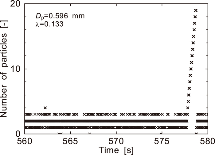
Figure 5 shows the variation of particle number existing in the calculation domain for the particles of 0.596 mm. The particle feeding rate is 0.553 kg m−2 s−1), and the dropping interval is 0.059 s. The particle existing number was sampled every 2.0 ms. The dropping interval is longer than the passage time for the free fall condition. Thus without the orifice, the existing number should be zero or unity. As shown in Fig. 3, the passage times for most particles are longer than 0.043 s due to the stagnation on the orifice. Consequently one to three particles usually exist in the calculation domain. Around 578 s, the existing particles suddenly increases. In this time range, the blockage of the orifice occurs and the powder particles are piled up on the orifice.
Number of particles existing in the calculation domain.
Figure 6 shows the formation process of the orifice blockage by the powder particles of 0.596 mm in diameter. The interval between the figures is 0.020 s. Two particles to initiate the blockage are depicted as dark color. The time shown in the figure is counted from the moment at which second particle is fed to the domain. At time 0 s, first particle is stagnant on the orifice due to the collisions to the orifice particles. From 0.04 to 0.06 s, first and second particles simultaneously enter the narrow part of the orifice at the same time. As a result, these two powder particles are stuck among the orifice particles. Around 0.06 s, third powder particle is fed to the central part of the top of the domain, and collides to the preceding two particles at 0.10 s. This collision brings little motion of two stuck particles, and finally these two particles settle there. The following particles are piled on these particles, and the blockage is formed. Under the conditions examined in this study, the blockage is initiated by only a few powder particles.
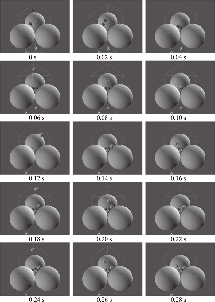
Formation of blockage.
In the previous section, the powder passage behavior through the orifice was explained under the conditions with 0.596 mm in diameter and the constant powder feed rate at 0.532 kg m−2 s−2. In this section, the effects of powder particle diameter, properties and feeding method on the passage behavior are discussed.
Figure 7 shows the effect of the powder particle diameter on the passage time. The passage time distributions for the particle diameters from 0.448 to 0.596 (the diameter ratio from 0.100 to 0.133 [–]) are plotted. The powder feed rate is constant at 0.532 kg m−2 s−1. Average passage times for all particle diameters are in the range from 0.107 to 0.110 s, and no significant difference are shown. The standard deviations of these distributions are 0.0268 s for 0.448 mm and 0.0209 s for 0.596 mm, and decreases with increase in the powder particle diameter. This tendency is same under the constant feed interval (0.03 s) condition.
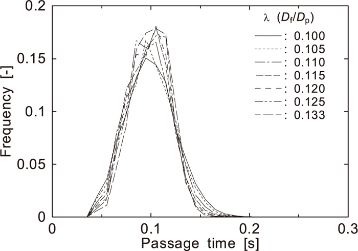
Effect of powder particle diameter on passage time.
Figure 8 shows the frequency of the blockage par 100000 particles. Under the constant dropping interval condition, the blockage frequency increases with the increase in the diameter ratio. Contrarily the blockage frequency shows the maximum at the diameter ratio of 0.11 [–] under the constant feed rate condition. With increase in the powder particle diameter, the ratio of projection area of powder particle to the area of the orifice opening increases, and it is considered that the blockage of the orifice opening by a few powder particles is more easily to occur. The number of the particles existing on the orifice under constant feeding interval condition is almost independent of the particle diameter because the average passage time shows little dependence on the powder particle diameter as mentioned above. Thus it is considered that the blockage frequency increases with the powder particle diameter. Under the constant feed rate conditions, the existing number of the powder particles on the orifice decreases with the increase in the particle diameter because the volume of single particle increases and the feeding interval is elongated. Consequently the blockage frequency in the larger particle diameter range decreases with the increase in the particle diameter.

Effect of powder particle diameter on blockage frequency.
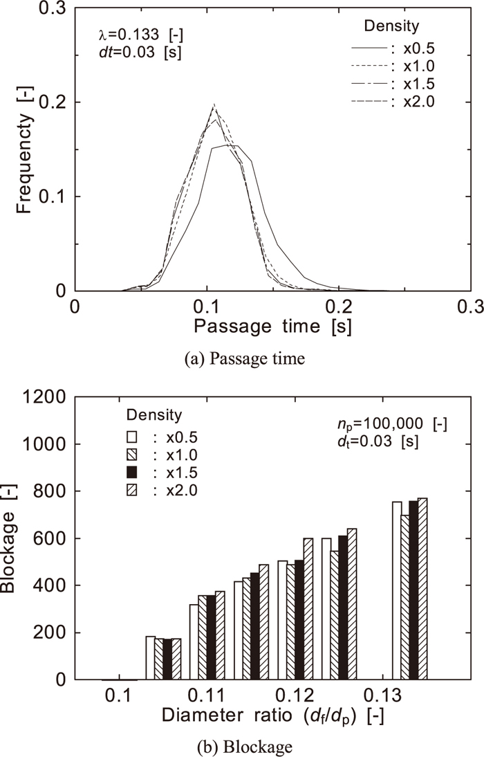
Figure 9 shows the effect of the density of the powder particle on the passage behavior under the condition with the particle diameter of 0.493 mm (diameter ratio 0.110 [–]) and constant dropping interval of 0.03 s. The density is varied from half to twice of the above-mentioned condition. With increase in the particle density, the average passage time slightly decreases. Contrarily the blockage frequency shows no clear relation to the particle density.
Effect of particle density on passage behavior.
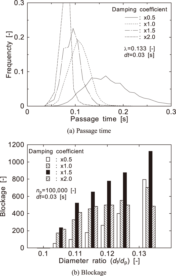
Figure 10 shows the effect of the damping coefficient on the passage behavior of the powder particles under constant dropping interval condition. With increase in the damping coefficient, the passage time shortens and its distribution narrows. The frequency of the blockage once increases then decreases with increase in the damping coefficient for each diameter ratio except for the ratio of 0.133. With smaller damping coefficient the powder particles strongly bounce in the upper space of the orifice. This behavior elongates the residence time and increases the existing number of the powder particles on the orifice. In this condition, distances among the powder particles are larger and the restitution is predominant in the powder behavior at the collisions. Thus it is considered that the chance of the orifice blockage formation is less with smaller damping coefficient. The increase in the damping coefficient weakens the bounce of powder particle after collision. The powder particles get closer one another, and the attenuation of powder momenta at the collision becomes stronger. Consequently the possibility of orifice blockage increases with the increase in the damping coefficient. With the doubled damping coefficient, the powder particle bounces little, and it merely rolls off along the surface of the orifice particle. This powder particle behavior shortens the passage time and decreases the number of the powder particles on the orifice. In this condition the powder particles tend to pass the orifice in the order of dropping, and the frequency of simultaneous falling of multiple powder particles decreases. As a result, the blockage frequency shows the maximum at the 1.5-times damping coefficient case.
Effect of damping coefficient on passage behavior.
Figure 11 shows the effect of rolling friction coefficient on the powder passage behavior through the orifice under constant dropping interval condition. The rolling friction coefficient has insignificant effect on both passage time and blockage frequency. In these calculating conditions, the motion of the powder particles is governed by the collision and bounce. Thus the rolling motion has minor effect on the passage behavior. During the formation of the blockage, the contacts among the particles increase and the rolling motion increases. This situation is generated after the blockage is already initiated by a few particles. Thus it is considered that the passage time and the blockage frequency are affected little by the rolling friction coefficient.

Effect of rolling friction on passage behavior.
The results of the analyses on passage behavior of the powder particle through the orifice consisting of the coarse particles can be summarized as follows. Under the constant powder dropping interval condition, the blockage frequency increases with the increase in the powder particle diameter. Contrarily the blockage frequency shows the maximum due to the balance between easiness of passage through the orifice and number of the powder particles on the orifice, under constant powder feed rate condition. The passage time of the powder particles through the orifice gets longer with the decreases in the particle density and the damping coefficient. It is caused by the strengthened rebound. The blockage frequency shows the maximum against the damping coefficient. These behaviors are caused by the balance between the easiness of bridging on the orifice due to the attenuation of particle kinetic energy and the frequency of simultaneous falling of multiple powder particles into the orifice. The rolling friction coefficient shows insignificant effects on the passage time and the blockage frequency. This is because the powder motion in this system is mainly characterized by the collisions and rebounds. Therefore, the particle properties, the mode of particle motion and the powder flow rate should be taken into account for the discussion on the powder behavior in the packed bed of actual blast furnace.
This study performed analyses of powder motion passing through the orifice consisting of the coarse particles by using the discrete element method, to discuss the fundamental behavior of the powder flow and the blockage formation in the packed bed of blast furnace. The results showed that only a few powder particles initiated the blockage of the coarse particle orifice in the conditions of this study. Additionally the effects of mechanical properties of the particles on the passage and the blockage behaviors were also revealed.
A part of this work was performed under the Cooperative Research Program of “Network Joint Research Center for Materials and Devices.”