Regular Article
Combustion Behavior of Pulverized Coal and Ash Particle Properties during Combustion
2015 Volume 55 Issue 6 Pages 1305-1312
Details
2015 Volume 55 Issue 6 Pages 1305-1312
CO2 emissions from blast furnaces should be reduced to curtail the impact of global warming. A promising solution is the low reducing agent rate (RAR) operation of blast furnaces. Char and ash particles derived from pulverized coal affect permeability in the furnace during low RAR operation. In our study, the combustion behavior and ash particle properties of pulverized coal during combustion were investigated. Char particles formed during combustion were sampled using a drop tube furnace, and then analyzed for their combustion ratio and ash particle properties. As a result, the combustion behavior of pulverized coal and properties of ash particles in raw coal were different by a coal type. Moreover, the combustibility of pulverized coal and the variation in ash particle properties during combustion were affected by the structure of the char particles.
CO2 emissions from steel industries make up approximately 15% of the total emissions in Japan. In particular, CO2 emissions from iron making processes, such as blast furnaces, coke ovens, and sintering machines, account for about 70% of all steel industry emissions1,2) since large amounts of carbonaceous materials, such as coke and pulverized coal, are used. These carbonaceous materials have essential roles: supplying heat and taking part in important reactions, such as reduction and carburization. Accordingly, a reduction in CO2 emissions from blast furnaces is urgently required to avoid global warming. A promising solution for CO2 reduction is the low reducing agent rate (RAR) operation of blast furnaces.
However, the thickness of the coke layer decreases while the thickness of the ore layer increases under low RAR operation. These changes affect permeability, which is one of the most important factors for the stable operation of a furnace. Yabata et al. found that the pressure drops in all parts of the blast furnace increased with an increase in the pulverized coal rate (PCR) under a high PCR operation.3) Additionally, with a high rate injection of pulverized coal, a shell layer derived from the ash of pulverized coals was formed at the depth of the raceway in the blast furnace. This shell layer caused an accumulation of fine particles on the deadman surface and a local flood of droplets, which affected the permeability at lower parts of the blast furnace.4)
In the case of a low carbon blast furnace (low coke rate: level of 200 kg/t-pig), it is guessed that the effect of pulverized coal on the permeability in the furnace relatively increases with decreasing coke rate. Therefore, it is very important to investigate the formation behavior of char particles (unburned char) that affects the permeability, that is, clarify the combustion behavior of pulverized coal and ash particle properties that cause shell layer formation at the depth of the raceway during combustion.
In this work, combustion experiments of two pulverized coals with ash of low and high melting points were conducted using a drop tube furnace. In addition to this, an observation of char particles and an analysis of ash particle properties (size, composition, and existence characteristics) by computer controlled scanning electron microscopy (CCSEM) were performed. Calculations of the molten slag ratios of ash particles by thermodynamic equilibrium theory were also carried out, in order to investigate experimentally the combustion behavior of pulverized coal and elucidate the fundamental ash particle properties during combustion.
Table 1 shows the properties of the pulverized coals used for this study. The melting points (following JIS M8801 method) of ash in Coal L and Coal H were 1280°C and over 1550°C in an oxidizing atmosphere, respectively. The JIS M8801 method is a method for determination of fusibility of ash. A shape change of a sample that was shaped into triangular pyramid is observed in a heating process. The melting point is defined when a ratio of width and height of the sample was set to 3 : 1.9) The average particle diameters of Coal L and Coal H were 46 μm and 34 μm, respectively. Table 2 shows the ash composition of samples.
| Sample | Proximate analysis (mass%) | Ultimate analysis (mass%) | |||||||
|---|---|---|---|---|---|---|---|---|---|
| a.r1) | dry base | d.a.f.2) | |||||||
| Moisture | VM | FC | Ash | C | H | N | S | O3) | |
| Coal L | 4.6 | 44.5 | 41.0 | 14.5 | 76.02 | 6.40 | 0.71 | 0.26 | 16.61 |
| Coal H | 2.7 | 32.8 | 55.0 | 12.2 | 81.40 | 5.26 | 1.83 | 0.50 | 11.01 |
| Sample | SiO2 | Al2O3 | Fe2O3 | CaO | MgO | Na2O | K2O | SO3 |
|---|---|---|---|---|---|---|---|---|
| Coal L | 41.30 | 23.80 | 7.21 | 12.50 | 3.47 | 2.13 | 0.81 | 3.32 |
| Coal H | 65.90 | 22.90 | 4.58 | 1.08 | 0.79 | 0.47 | 1.37 | 0.62 |
Coal combustion experiments were conducted using a drop tube furnace equipped with an external electric heater, as shown in Fig. 1. Pulverized coal was continuously fed into an injector by a rotary table feeder. The injector was a stainless steel double pipe equipped with water-cooling. Pulverized coal was injected into the reactor by a carrier gas (N2). The reactor was a mullite tube, with 2 m in length and an inner diameter of 70 mm. The temperature in the reactor was controlled with an external electric furnace containing silicon carbide heating elements. A water-cooled sampling probe with an inner diameter of 10 mm was inserted from the bottom of the reactor tube. Char particles entrained in the combustion gas were extracted from the reactor using this sampling probe. The sampling point of the probe head was set at distances between 100 mm and 1300 mm from the injector. Char particles were collected in a thimble filter downstream of the probe for an estimation of the combustion ratio and CCSEM analysis. Table 3 shows the experimental conditions for the coal combustion experiments. The O2 concentrations were fixed to obtain char particles with a wide range of combustion ratios.

Schematic diagram of drop tube furnace.
| Sample | Coal L | Coal H |
|---|---|---|
| Air ratio [–] | 1.1 | 1.1 |
| Furnace temperature [°C] | 1400 | 1400 |
| Sample feed rate [g/min] | 0.8 | 1.0 |
| O2 concentration [%] | 6 | 8 |
In order to estimate the combustion ratios of char particle samples, the carbon and ash content of the char particles was determined by thermo-balance (following JIS M8812 method). The combustion ratio was calculated using the ash tracer method with Eq. (1). It was assumed that the weight of ash content did not change during the combustion of pulverized coal.
| (1) |
CCSEM5,6) was used to analyze the particle size, elemental composition, and existence characteristic of ash particles in char samples. The CCSEM system used consisted of a Scanning Electron Microscope (SEM) and an Energy Dispersive X-ray Spectrometer (EDS). The smallest particle size that could be determined by our CCSEM system was about 1 μm. Three magnifications were selected during CCSEM analysis: ×800 for particles of 1.0–4.6 μm, ×240 for 4.6–22 μm, and ×50 for 22–200 μm. Five selected images with each magnification were observed and analyzed. For sample preparation, the char samples obtained were embedded in carnauba wax. These waxed samples were carefully cross-sectioned and polished.
Back-Scattered Electron (BSE) images of the cross-section of char samples were collected, as shown in Fig. 2. The BSE images were binarized using particle analysis software to distinguish between ash particles and other materials (carbonaceous matrix and carnauba wax). The diameter of individual ash particles was determined by the particle analysis software, and the elemental composition was determined with EDS. In regard to the existence characteristics of ash particles, the particles embedded in the carbonaceous matrix are defined as included minerals (IM), while those kept separate from the carbonaceous matrix are defined as excluded minerals (EM), as shown in Fig. 2.
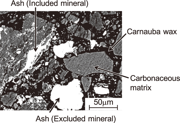
BSE image of a cross-section of coal.
In order to evaluate the melting characteristic (meltability) of the ash particles of each sample, molten slag ratios were calculated by thermodynamic equilibrium theory with FactSage Ver. 6.3 software.7,8) This software has special thermodynamic databases on non-ideal liquid species, and therefore it can simulate the compositions of non-ideal liquid species through the minimization of the Gibbs’s free energy of all phases as functions of temperature and composition.
The initial input compositions of ash particles were the average compositions of IM and EM ash particles in the raw coal and char samples. Combustion ratios of char samples used were 69.1% for Coal L and 70.9% for Coal H. The atmospheres used for calculations were an oxidizing atmosphere (79% N2, 21% O2) and a reducing atmosphere (60% CO, 40% CO2). These calculations were performed at 50°C increments between 1000 and 2000°C in each atmosphere to determine the mass percentage of molten slag in the samples. The databases used for these calculations of the oxidizing atmosphere and the reducing atmosphere were FToxid-SLAG B (slag with oxide and sulfate) and FToxid-SLAG A (slag with oxide and sulfide), respectively.
Figure 3 shows the combustion ratios with sampling point distance from injector for Coals L and H. Although the O2 concentration for Coal L was lower than that of Coal H, the combustion ratio of Coal L was higher. From this result, it is clear that the combustibility of Coal L is better than Coal H. This is because the fuel ratio (FC/VM) of Coal L (0.92) is smaller than that of Coal H (1.67), in other words, Coal L contains more volatile matter (VM) than Coal H.

Combustion ratio curves of Coal L and Coal H.
Figures 4 and 5 show BSE images of the cross-section of char particles with different combustion ratios for Coals L and H, respectively. The white, gray, and black parts are the ash particles, carbonaceous matrices, and carnauba wax, respectively. In the case of Coal L (Fig. 4), carbonaceous matrices with a network-like structure were observed in char particles with a combustion ratio of 34.9%. The network-like structure increased with increasing combustion ratio. On the other hand, in the case of Coal H (Fig. 5), carbonaceous matrices with a balloon-like structure were observed in char particles with a combustion ratio of 28.1%. This is because the carbonaceous matrix softens and swells with the release of volatile matter from the coal. Also, the walls of the carbonaceous matrix with a balloon-like structure thinned and disintegrated with an increasing combustion ratio. These results indicate that the structure of char particles formed during the combustion of pulverized coal is different by a coal type. It can be inferred that the surface area of char particles with the network-like structure is larger than those with the balloon-like structure from Figs. 4 and 5. Therefore, it is guessed that the combustibility of Coal L improves with both larger surface area and VM content than Coal H, as shown in Fig. 3. Hence, the structure of char particles affects the combustibility of pulverized coal.

BSE images of cross-sections of Coal L during combustion.

BSE images of cross-sections of Coal H during combustion.
Figure 6 shows the number fractions of IM and EM particles in char samples with different combustion ratios for Coals L and H. Approximately 70% of ash particles in raw Coal L were IM particles. In contrast, over 90% of ash particles in raw Coal H were IM, as shown in Fig. 5. These results indicate that the existence characteristic of ash particles in raw coal depends on a coal type.

Number fractions of included and excluded mineral particles for Coal L and Coal H.
In the case of Coal L, the number fraction of EM particles gradually increased with increasing combustion ratio. The number fraction of EM particles was almost equal to the number fraction of IM particles when the combustion ratio reached 69.1%. This is because IM particles are detached from the carbonaceous matrix in the char particle as the combustion progresses. On the other hand, in the case of Coal H, the number fraction of EM particles drastically increased with increasing combustion ratio. The number fraction of EM particles was about 70% when the combustion ratio reached 70.9%. From these results, the variation in the number fractions of IM and EM particles during the combustion of pulverized coal are different by a coal type.
Figure 7 shows the number fractions of IM particles for various ash particle sizes (1–3, 5–10 μm). For both coals, a smaller particle size (1–3 μm) correlated with a majority of IM particles. In particular, the number fraction of IM particles was very high for Coal H (approximately 90%). In the case of Coal L, the number fraction of IM particles of size 1–3 μm gradually decreased with increasing combustion ratio. With particle sizes of 5–10 μm, Coal L had a lower number fraction of IM but it was almost constant with increasing combustion ratio. The reason for this is that smaller IM particles (1–3 μm) are difficult to detach from the network-like carbonaceous matrix in Coal L char particles. Therefore, the number fraction of IM particles for Coal L remains relatively constant compared to Coal H throughout combustion. Additionally, there is a possibility that the smaller IM particles (1–3 μm) melt and coalesce with other IM particles within the carbonaceous matrix. This coalescence of IM particles explains the increase in the fraction of 5–10 μm particles. Therefore, it is guessed that the invariable number fraction of IM particles of 5–10 μm results from the balance between the decrease by the detachment of 5–10 μm particles and the increase by the coalescence of 1–3 μm particles. On the other hand, in the case of Coal H, the number fraction of 1–3 and 5–10 μm IM particles both drastically decreased with increasing combustion ratio. As discussed previously, this is because a large fraction of IM particles are detached from the balloon-like carbonaceous matrix in the char particle when it softens and swells during combustion. While there is a possibility of the coalescence effect of IM particles, as discussed for Coal L, the number fraction of 5–10 μm IM particles drastically decreases through detachment. These results indicate that the structure of char particles affects the existence characteristic of ash particles during the combustion of pulverized coal.
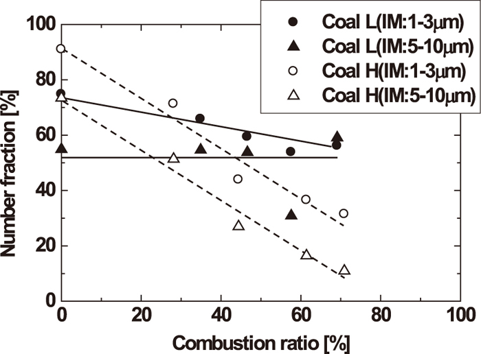
Number fractions of included mineral particle with particle diameter during combustion.
Figure 8 shows the variation in SiO2+Al2O3 concentration of IM and EM particles during combustion. For Coal L, SiO2+Al2O3 concentrations in IM and EM particles of the raw coal were almost equal, and scarcely changed with the progress of combustion. Unlike Coal L, the SiO2+Al2O3 concentration in EM particles of raw Coal H was approximately 30% less than that of IM particles. For Coal H char samples, the concentration in EM particles increased with increasing combustion ratio, and the concentrations in IM and EM particles were almost equal when the combustion ratio reached 70.9%. This is because IM particles containing SiO2 and Al2O3 at higher concentrations than EM particles become detached from the carbonaceous matrix during combustion, and so are converted to EM particles.

SiO2 and Al2O3 concentration in included and excluded mineral particles during combustion.
The variation of Fe2O3 and MgO concentrations during combustion are shown in Figs. 9 and 10, respectively. For Coal L, there was little difference in the Fe2O3 concentrations of IM and EM particles, and this did not change during combustion. In the case of raw Coal H, the Fe2O3 concentration in EM particles was much larger than that of IM particles, but the Fe2O3 concentrations in EM particles decreased to that of IM particles with increasing combustion ratio. This is because the Fe2O3 concentration in EM particles is reduced by the conversion of low concentration IM particles to EM particles. For both coal samples, the MgO concentrations displayed the same behavior as shown by Fe2O3 concentrations.

Fe2O3 concentration in included and excluded mineral particles during combustion.

MgO concentration in included and excluded mineral particles during combustion.
The variation of CaO and SO3 concentrations during combustion are shown in Figs. 11 and 12, respectively. The CaO concentrations for both coals had a small dispersion, but there was hardly any difference between IM and EM particles, and they did not change during combustion. The SO3 concentration in both IM and EM particles for Coal L gradually decreased with increasing combustion ratio. On the other hand, in the case of raw Coal H, the SO3 concentration in EM particles was much larger than that of IM particles, but decreased to IM levels with the onset of combustion. The decrease of SO3 concentration results from the vaporization of sulfur as SO2 gas during combustion. These results show that the IM and EM ash compositions are different by a coal type, but the differences between IM and EM ash compositions decrease during combustion.

CaO concentration in included and excluded mineral particles during combustion.

SO3 concentration in included and excluded mineral particles during combustion.
Figures 13 and 14 show the temperature dependence of molten slag ratios in the oxidizing atmosphere for IM and EM ash particles in raw and char samples (combustion ratios of 69.1% for Coal L and 70.9% for Coal H), respectively. For raw Coal L, the molten slag ratio of EM particles was approximately 10% larger than that of IM perticles below 1500°C. On the other hand, in raw Coal H, the molten slag ratio of EM particles was much smaller than that of IM particles, and these differences became larger at higher temperatures. Moreover, the molten slag ratios of IM particles in raw Coals H and L were equal. This result indicates that the meltability of EM particles in raw Coal H (i.e., coal with ash of a high melting point) is low. The results also show that the meltability of IM particles in raw Coal H is almost equal to that of IM and EM particles in raw Coal L (i.e., coal with ash of a low melting point). For the char samples of Coal L, the molten slag ratio of EM particles was approximately 20% larger than that of IM particles at temperatures of less than 1700°C. However, they were almost identical at 1700°C and above. On the other hand, in the case of Coal H, the molten slag ratios of IM and EM particles were almost identical at all temperatures, unlike raw Coal H. This is caused by the detachment of the IM particles from the carbonaceous matrix, converting IM to EM particles, with the progress of combustion.

Molten slag ratio of ash in raw coals with temperature in an oxidizing atmosphere.

Molten slag ratio of ash in char particles with temperature in an oxidizing atmosphere.
Figures 15 and 16 show the temperature dependence of molten slag ratios in the reducing atmosphere for IM and EM ash particles in raw coals and char samples (combustion ratios of 69.1% for Coal L and 70.9% for Coal H), respectively. For raw Coal L, the molten slag ratio of EM particles was approximately 10% larger than that of IM particles at temperatures of less than 1600°C, similar to the oxidizing atmosphere. On the other hand, the molten slag ratio of IM particles in raw Coal H showed similar trends to raw Coal L in the reducing atmosphere, but the molten slag ratio of EM particles was larger than that of IM particles at temperatures of less than 1400°C. From this result, it is guessed that the meltability of EM particles in raw Coal H (i.e., coal with ash of a high melting point) is higher. The results also show that meltability of IM particles in raw Coal H is almost equal to that of IM and EM particles in raw Coal L (i.e., coal with ash of a low melting point) in the reducing atmosphere. For the char samples of Coal L, the molten slag ratio of EM particles was much larger than that of IM particles, but they were almost equal at 1700°C and above. On the other hand, in the case of Coal H, the molten slag ratios of IM and EM particles showed the similar trends at all temperatures to that of Coal H in the oxidizing atmosphere.

Molten slag ratio of ash in raw coals with temperature in a reducing atmosphere.

Molten slag ratio of ash in char particles with temperature in a reducing atmosphere.
From these results, when the compositions of IM and EM ash particles in raw coal are different, their meltability during the initial stages of combustion is different. However, with the progress of combustion, IM and EM ash particles have the same meltability, so the compositions of ash particles become equal. This is because of the detachment of IM particles from the carbonaceous matrix in the char particle. This suggests that the properties of IM and EM ash particles are important in order to comprehend the ash particle behavior during the combustion of pulverized coal.
Combustion experiments of two pulverized coals with ash of different melting points were conducted using a drop tube furnace. The properties of ash particles in the coals were analyzed by CCSEM in order to elucidate the combustion and ash particle behavior of pulverized coal during combustion. The following results were obtained.
(1) The structure of char particles affects the combustibility of pulverized coal. Therefore, the combustibility of coal is improved by having smaller fuel ratios (FC/VM) and char particles with a network-like structure.
(2) Approximately 70% and over 90% of ash particles in raw Coal L and raw Coal H were IM particles, respectively. The existence characteristic (IM, EM) of ash particles in raw coal depends on a coal type.
(3) The number fraction of EM particles in Coal L gradually increased with increasing combustion ratio, while the number fraction of EM particles in Coal H drastically increased with increasing combustion ratio. The variation in the number fractions of IM and EM particles during combustion is different by a coal type, and affected by the structure of the char particles.
(4) The composition of IM and EM ash particles in Coal L are almost identical, and this hardly changed during combustion, with the exception of SO3. On the other hand, the composition of IM and EM particles in Coal H were different, but the differences became less pronounced with the progress of combustion.
(5) For Coal L in the oxidizing and reducing atmosphere, the molten slag ratio of EM particles was larger than that of IM particles. On the other hand, for Coal H, the molten slag ratio of EM particles was smaller than that of IM particles in the oxidizing atmosphere, but they were equal in the reducing atmosphere.
This work was partially performed by a Research Group for Optimization of Transport Phenomena for Low Carbon Blast Furnace, in The Iron and Steel Institute of Japan (the chief examiner is Prof. S. Ueda, from Tohoku Univ.). The authors would like to acknowledge the contribution of all research group members.