Abstract
A variable-velocity stirring method is proposed to improve the desulfurization efficiency of high-sulfur hot metal for KR desulphurization process. The mixing behavior of desulfurizer and high-sulfur hot metal under the variable-velocity stirring method is investigated using the Euler-granular model. The particle volume fraction, mixing time and power consumption are discussed to illustrate the entrainment and dispersion of desulfurizer. The results show that the flow field of hot metal and the entrainment and dispersion of desulfurizer are improved obviously under the variable-velocity stirring method. The particle volume fraction distribution is uniform and the mixing time is short under the stirring mode of 90–50 rpm for 8 s switch with the moderate power consumption and torque. The stirring mode of 90–50 rpm for 8 s switch is recommended to adopted within the present system, which can optimize the entrainment and dispersion of desulfurizer in the bath.
1. Introduction
KR mechanical stirring method is used widely in the process of hot metal desulphurization. Due to the instability of the iron ore and raw materials for metallurgy, the composition, the temperature and the slag amount of hot metal fluctuate. The constant-velocity stirring mode is used to handle the high-sulfur hot metal desulphurization in the traditional KR stirring method. For the low temperature (<1250°C) and high-sulfur ([S%]>0.060%) hot metal desulphurization, it is difficult to achieve the desulphurization target due to the constant-velocity, and the high desulfurizer consumption and the high temperature drop are inevitable.
The study on the high-sulfur hot metal desulfurization using the KR stirring method has received intensive attention recent years, and the flow state and mixing characteristics of the constant-velocity KR stirring desulfurization have been analyzed experimentally and numerically. In order to improve the desulfurization efficiency of high-sulfur hot metal, Yang et al.,1) Socha et al.2) and Li et al.3) investigated the properties of desulfurizer. They found that the desulfurization efficiency can be increased by improving the particle size of the desulfurizer, adding active agent or adopting advanced desulfurizer. Deng et al.,4) Ouyang et al.,5) Ji et al.6) studied dynamics conditions in the stirring flow field under constant-velocity stirring mode, Deng et al.4) changed the position of the stirring by increasing of impeller eccentricity, Ouyang et al.5) developed the structure of impeller with a new type WG-3Y stirrer, Ji et al.6) increased the disturbance device with the new type of disc impeller. Shiba et al.7) investigated the operation parameters and the structure parameters on the constant-velocity KR desulfurization process, and Nakai et al.8) changed the velocity and the depth of impeller in order to understand the effect of particles dispersion in KR mechanically-stirred vessel under the constant-velocity stirring method. Wu et al.,9,10) Liu et al.11) decreased the mixing time and developed the efficiency of the desulfurization by adopting different rotation modes under the other refine process.
So far, intensive researches have been carried out to improve the desulphurization efficiency of hot metal under the constant-velocity stirring mode, which indicate that the improving of dynamics conditions is the key to increase the desulphurization efficiency of hot metal. The mixing between the hot metal and the desulfurizer would be more direct and quick if dynamics conditions can be improved. However, the improvement of dynamics conditions is limited under the constant-velocity stirring mode. To overcome the difficulty, a variable-velocity stirring method has been proposed to improve the desulphurization efficiency of hot metal by improvement of dynamics conditions under lower rotation speeds in the present work. The desulphurization efficiency is analyzed by investigating the entrainment and dispersion of the desulfurizer in the hot metal.
2. Mathematical Models
2.1. Geometric Model and Mesh Generation
The research object is a cylindrical vessel contained with the hot metal. The surface of the hot metal is sprinkled with lime and a cross-shaped impeller coated with refractory materials is used to conduct stirring. The sizes of vessel and other parameters adopted in the present model are listed in Table 1. The vessel and impeller type are showed in Fig. 1. The variable-velocity mode is adopted under different variable-velocity switch time and different rotation range. The variable-velocity switch time T is 8 s, 12 s, and 16 s, respectively. The minimum rotation velocity is fixed at Nmin=50 rpm, and the maximum rotation velocity is increased from 70 to 150 rpm with a increment of 10 rpm. Figure 2 shows the schematic of the variable-velocity modes. The initial mass of lime is 15 kg/ ton iron.
Table 1. Equipment size and operating parameters.
| Parameter | Value |
|---|
| Impeller immersion depth (m) | 0.15 |
| Axis diameter (m) | 0.04 |
| Lime size (mm) | 1 |
| Lime density (Kg/m3) | 1500 |
| Working medium | Hot metal-lime |
An unstructured tetrahedron grid is used, and part of grids are made densely around the impeller shown in Fig. 3. Grids in the bath are divided into an inner and an outer area. For the outer area, it is solved at a static coordinate system, and it is solved in a rotating coordinate system for inner area including the impeller. The calculation results for the rotating part are returned to the static coordinate system after transformation, and they are matched in the boundary of two grid areas. The grid independence is determined using different grids, and total number of grids are 800 thousands.
2.2. Initial Conditions and Boundary Conditions
The free surface of hot metal is supposed to be flat at initial time and a layer of lime is sprinkled on the free surface of hot metal. The wall of the bath is defined as a no-slip wall, and the scalable wall function is adopted for the close-to-wall area. The slip grid condition is selected for the inner area near the impeller, and the velocity variation is defined according to patterns shown in Fig. 2.
2.3. Governing Equations
The Euler-granular model describes the granules, which is used at present work.
Mass conservation equation,
|
∂(
α
q
ρ
q
)
∂t
+∇⋅(
α
q
ρ
q
U
q
)
=0,
| (1) |
Liquid phase momentum conservation equation,
|
∂(
α
l
ρ
l
U
l
)
∂t
+∇⋅(
α
l
ρ
l
U
l
U
l
)
=-
α
l
∇p+∇⋅
τ
l
¯
¯
+
α
l
ρ
l
g+
F
ls
+
R
ls,l
,
| (2) |
Solid phase momentum conservation equation,
|
∂(
α
s
ρ
s
U
s
)
∂t
+∇⋅(
α
s
ρ
s
U
s
U
s
)
=-
α
s
∇p-∇
p
s
+∇⋅
τ
s
¯
¯
+
α
s
ρ
s
g+
F
ls
+
R
ls,s
,
| (3) |
where
τ
q
¯
¯
is tensor of shear stress which is also named Renault stress terms. According to Boussinesq’s hypothesis, fluid phase is written as:
|
τ
l
¯
¯
=
α
l
μ
l
(∇
U
l
+∇
U
l
T
)+
α
l
(
λ
l
-
2
3
μ
l
)
∇⋅
U
l
| (4) |
represents pressure acting on liquid phase, and it in turbulence flow is replaced by the corrected pressure
p′:
|
p
′
=p+
2
3
μ
q
∇⋅
U
q
+
2
3
ρ
q
k
q
=-
α
q
∇p+∇⋅(
α
q
μ
q
(∇
U
q
+
(∇
U
q
)
T
)),
| (5) |
where
μl is the effective viscosity of fluid phase which should be calculated using the liquid phase turbulence model. In this paper, RNG
k-
ε model is adopted. The extra pressure of solid phase ∇
ps, stress-strain tensor in the solid phase
∇
τ
s
¯
¯
, and solid phase shear viscosity
μs need to be determined by the kinetic theory of granular flow theory, and the detailed method can be found in Ref.
12).
In Eqs. (2) and (3), Fls is the centrifugal force of Corillis force under the rotating stirring mode, which is shown as,
|
F
q
=-2
α
q
ρ
q
N×U-
α
q
ρ
q
N×(N×r),
| (6) |
and
Rls is the inter phase momentum exchange term. Because the huge difference between solid particles density and liquid phase density, the drag force, buoyancy force and virtual mass force are considered with referring to the research of Tatterson
et al.13) Gidespow model
14) is used as the drag force model, Thomas model
15) is used as the buoyancy force, and Lopez de Bertodano model
16) is used as the virtual mass force, respectively.
3. Results and Discussions
3.1. Simulation Verification
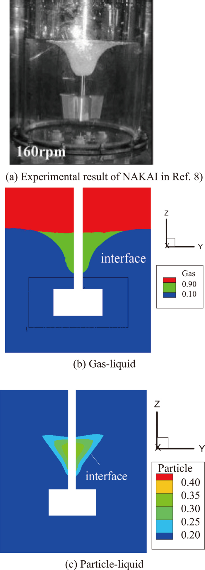
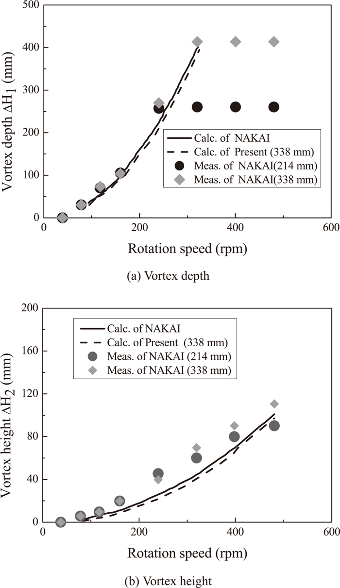
The model verification has been carried out using the device and parameters in Ref. 8) which is listed in Table 2, and the impeller used is shown in Fig. 4. Figure 5 shows the comparison between the present particle volume fraction distribution under the constant-velocity stirring mode with 160 rpm and those in Ref. 8) (see Fig. 3(I) in Ref. 8)). Figure 6 shows the relationship between the present results of vortex depth and vortex height and those in Ref. 8). The adopt impeller immersion depth in our computation is 338 mm. It can be seen that the present results are in good agreement with results in Ref. 8).
Table 2. Device size and operating parameters in Ref.
8).
| Parameter | Value |
|---|
| Bath diameter (m) | 0.523 |
| Bath height (m) | 0.695 |
| Level height (m) | 0.414 |
| Impeller immersion depth (m) | 0.214 and 0.338 |
| Blade length (m) | 0.203 |
| Blade width (m) | 0.052 |
| Blade height (m) | 0.11 |
| Impeller rotation velocity (rpm) | 0–480 |
| Working medium | Particle/water |
| Particle density ( g/cm3) | 0.03 |
| Particle diameter (mm) | 2 |
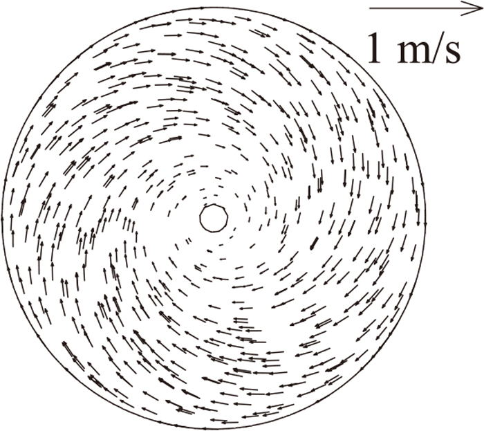
The entrainment velocity of desulfurizer impact the desulfurization efficiency of high-sulfur hot metal directly. The impeller makes the hot metal rotating and the vortex occurs on the surface of hot metal. The entrainment velocity of desulfurizer in the hot metal is related to the structure of the vortex. The vortex depth and velocity vectors of hot metal surface under the constant-velocity stirring mode are shown in Figs. 7(a) and 8, respectively. The hot metal surface forms stable vortex with a constant depth under the traditional constant-velocity stirring mode in Fig. 7(a). It can be seen from Fig. 8 that the hot metal rotates at the smaller velocities in the vortex core, and the velocities at other area are larger. The difference between velocities in the vortex core and those at other area is small, which has weak capacity to entrain the desulfurizer.
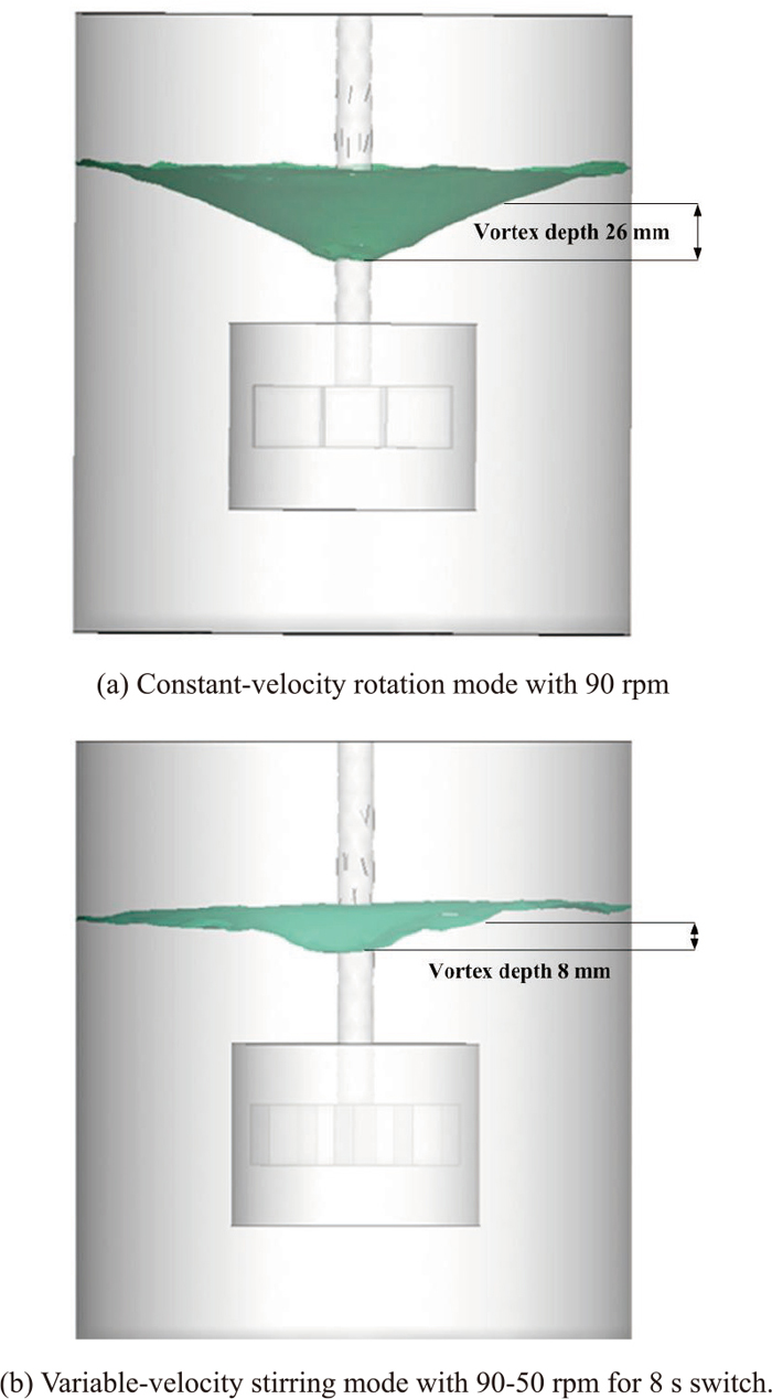
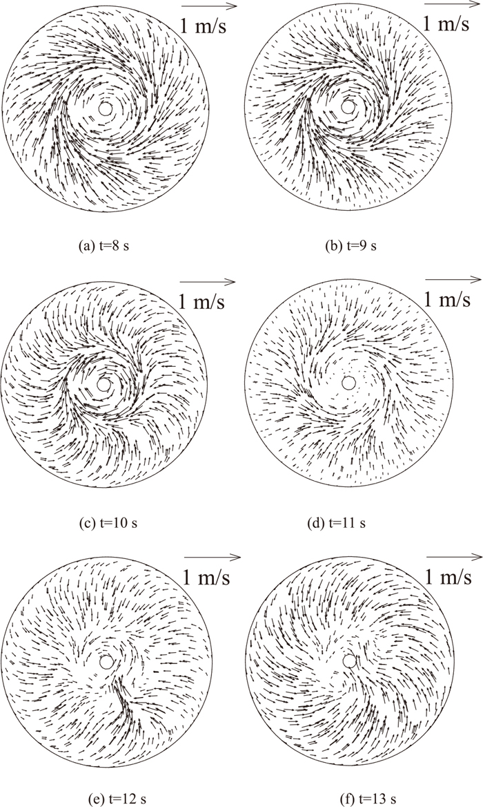
The average vortex depth and velocity vectors of hot metal surface at different time under the variable-velocity stirring mode with 90–50 rpm for 8 s switch are shown in Figs. 7(b) and 9, respectively. The depth of vortex at variable-velocity stirring mode is smaller than that at constant-velocity under the same maximum rotation velocity. The depth of vortex continually changes and the entrainment capacity of desulfurizer increases intensively under the variable-velocity stirring mode. This is due to the periodical variation of velocities at vortex core along the clockwise and anticlockwise directions, resulting in the occurrence of many small vortexes which have a strong entrainment capability to the desulfurizer.
3.2.2. Effect of Stirring Modes on the Desulfurizer Dispersion Efficiency
The dispersion uniformity is the key to improve the desulfurization efficiency after the desulfurizer is entrained into the hot metal. Figure 10 shows velocity vectors of hot metal under constant-velocity stirring mode with 90 rpm. Four symmetrical swirls occur near the end face of the impeller, which is favorable to disperse the desulfurizer in these region. However, the cylindrical-type isolated rotation area is formed due to the low flow velocities in the area upper the impeller, which inhibits the diffusion of desulfurizer. The velocities are almost zero at the area below the impeller. Therefore, it is difficult for the desulfurizer to reach this area and the dispersion efficiency is low.
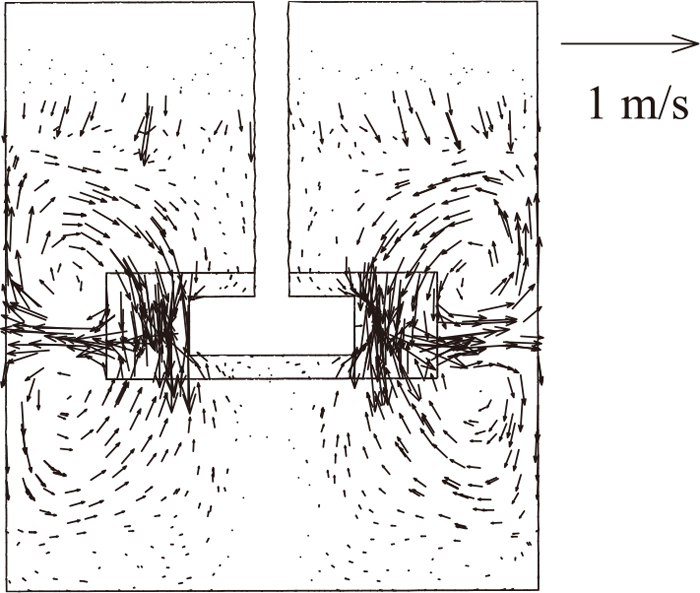
Figure 11 shows the velocity vectors of hot metal at a certain moment under the variable-velocity stirring mode with 90–50 rpm for 8 s switch. Many small swirls are formed because the shearing effect of impeller changes with time at variable-velocity stirring mode. The swirls appear in different locations in different time and the swirl structure changes in the variable-velocity stirring mode. Especially, the swirls in the region under the impeller and around the impeller’s shaft inhibit the formation of cylindrical-type isolated rotation area. Therefore, a better mixing effect is realized, which is very important on the dispersion of desulfurizer.
3.3. Effect of Stirring Modes on Power Consumption and Torque
It can be seen from the above analysis that the variable-velocity stirring mode can improve the entrainment and dispersion of desulfurizer. With increasing the range of variable velocity or decreasing the switch time, efficiencies of entrainment and dispersion increase. The stress of the stirring shaft and the power consumption may be enhanced when the velocity is changed, therefore, it is necessary to analyses the torque and power consumption. For the variable-velocity stirring mode, Nmax varies from 70–130 rpm and Nmin keeps constant at 50 rpm, and the switch times is 8 s, 12 s and 16 s, respectively. The stirring velocity is kept constant value varying from 70–130 rpm at different cases for constant-velocity stirring modes. The pressure force, shear force and centrifugal force exerted on the unit length of impeller blade are given by the formula (2), (3), (4), (5), (6). The torque
M=∫
rdF
, and the power consumption P=Mω. The maximum value of power consumptions and torques under different stirring modes are shown in Tables 3, 4.
Table 3. Power consumptions under different stirring modes (W).
Rotating velocity
Stirring mode | 130–50 rpm | 120–50 rpm | 110–50 rpm | 100–50 rpm | 90–50 rpm | 80–50 rpm | 70–50 rpm |
|---|
| Rotating in variable-velocity for 8 s switch | 78. 4 | 64.8 | 52.3 | 41.6 | 29.7 | 22.2 | 13.9 |
| Rotating in variable-velocity for 12 s switch | 63.3 | 51.8 | 40.1 | 28.8 | 20.9 | 13.2 | 10.2 |
| Rotating in variable-velocity for 16 s switch | 50.6 | 40.0 | 28.4 | 20.6 | 13.1 | 10.4 | 6.9 |
| Constant-velocity rotating mode1 | 44.6 | 29.0 | 17.6 | 13.2 | 9.6 | 6.8 | 4.5 |
1 Note: Rotation velocity under the constant-velocity rotation mode is the maximum velocity of corresponding rotation velocity range.
Table 4. Torques under different stirring modes (N·m).
Rotating velocity
Stirring mode | 130–50 rpm | 120–50 rpm | 110–50 rpm | 100–50 rpm | 90–50 rpm | 80–50 rpm | 70–50 rpm |
|---|
| Rotating in variable-velocity for 8 s switch | 5.76 | 5.15 | 4.54 | 3.97 | 3.15 | 2.65 | 1.89 |
| Rotating in variable-velocity for 12 s switch | 4.65 | 4.12 | 3.19 | 2.75 | 2.18 | 1.57 | 1.39 |
| Rotating in variable-velocity for 16 s switch | 3.71 | 3.18 | 2.46 | 2.07 | 1.52 | 1.28 | 0.94 |
| Constant-velocity rotating mode1 | 2.84 | 2.13 | 1.53 | 1.26 | 1.02 | 0.80 | 0.62 |
1 Note: Rotation velocity under the constant-velocity rotation mode is the maximum velocity of corresponding rotation velocity range.
It can be seen from Tables 3, 4 the power consumption and the torque under variable-velocity stirring mode are larger than that under the constant-velocity stirring mode at the same maximum rotation velocity. With increasing the range of variable velocity or decreasing the switch time, the power consumption and torque increases, and the influence of switch time on the power consumption and the torque is larger slightly than that of the rotating velocity range for the present system. These data can help us to find the most suitable model which ensures the entrainment and satisfy the requirement having the minimum torque and power consumption at the same time.
3.4. Turbulence Kinetic Energy near the Bottom of the Bath
The mixing is difficult in the area under the impeller. It is desirable to find a reasonable stirring mode which meets the mixing requirement by analyzing the energy offered to the area under the impeller. The origin of coordinates is located in the center of the impeller, and a monitoring point at the location of (0, 0, −0.1) is set up. The velocity changes from 100–50 rpm to 80–50 rpm, and switch time is 8 s, 12 s, and 16 s, respectively. The variation of turbulent kinetic energy at this point is shown in Fig. 12 under the variable-velocity mode and constant-velocity mode.
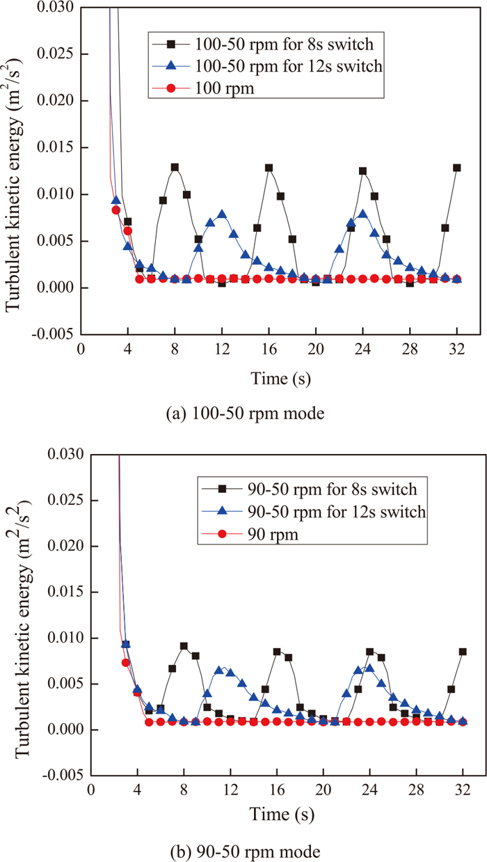
It can be seen from Fig. 12 that the turbulent kinetic energy presents cycle oscillation under variable-velocity stirring mode at the monitoring point, and the values are 0.13–0.005 m2/s2 and 0.09–0.004 m2/s2 under 100–50 rpm for 8 s switch and 90–50 rpm for 8 s switch, respectively. While the turbulent kinetic energy 0.08–0.005 m2/s2 and 0.07–0.004 m2/s2 under 100–50 rpm for 12 s switch and 90–50 rpm for 12 s switch, respectively. It is obvious that the influence of rotating speed on the turbulent energy is less than that of the switch time on the turbulent energy for the present system. The mixing effect under the model of 90–50 rpm for 8 s is better than that under 100–50 rpm for 12 s.
3.5. Effect of Stirring Modes on the Mixing Behavior
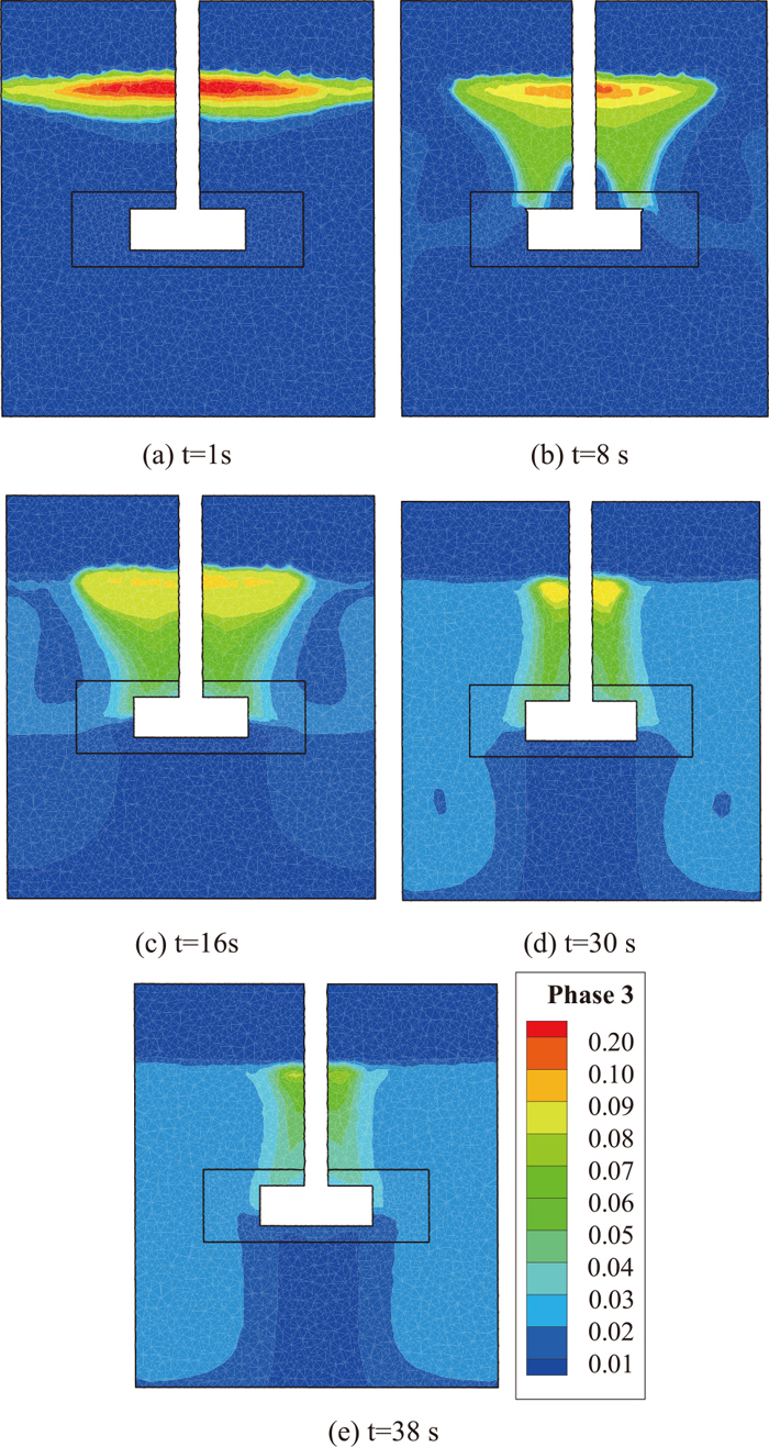
Figures 13, 14, 15 show the entrainment and dispersion of the desulfurizer at different time under variable-velocity stirring mode with 90–50 rpm for 8 s switch, 90–50 rpm for 12 s switch and 80–50 rpm for 8 s switch, respectively. It can be seen that the entrainment efficiency of desulfurizer is different under the different modes. The dispersion is homogeneous and the particle volume fraction reaches a value of 0.03 after t=20 s except for the area near shaft and the bottom of the bath under the velocity with 90–50 rpm for 8 s switch. The mixing time and homogeneous degree of dispersion are deteriorated under the other two modes. The mixing time and homogeneous degree of dispersion under the stirring mode with 80–50 rpm for 8 s switch are superior to that obtained under 90–50 rpm for 12 s switch, but the particle volume fraction is lower under the mode of 80–50 rpm for 8 s switch. Obviously, the switch time of variable-velocity has a greater influence on the mixing time and the distribution uniformity of particle, and the range of variable velocity affects greatly values of particle volume fraction.

The quick mixing of desulfurizer can reduce the desulfurizer waste and improve the reaction efficiency. The mixing time of desulfurizer and hot metal refers to the time span from the desulfurizer being entrained to the particle volume fraction reaching the steady state. In order to analyze the effect of variable velocity range and switch time on the desulfurizer dispersion, three typical monitoring points shown in Fig. 16. The point 1 is located at (0, 0.006, 0.17) which is close to the liquid surface and nearby the stirring shaft. The particle volume fraction of desulfurizer at point 1 is calculated to investigate entraining level of the desulfurizer in the stirring process. The point 2 is located at (0, 0.11, 0) which is near the end of impeller, and the particle volume fraction of desulfurizer at point 2 is calculated to investigate the reference value of uniform mixing. The point 3 is located at (0, 0, −0.1) in which it is difficult for the desulfurizer to reach.
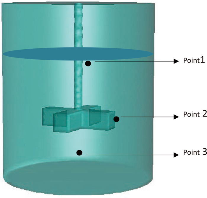
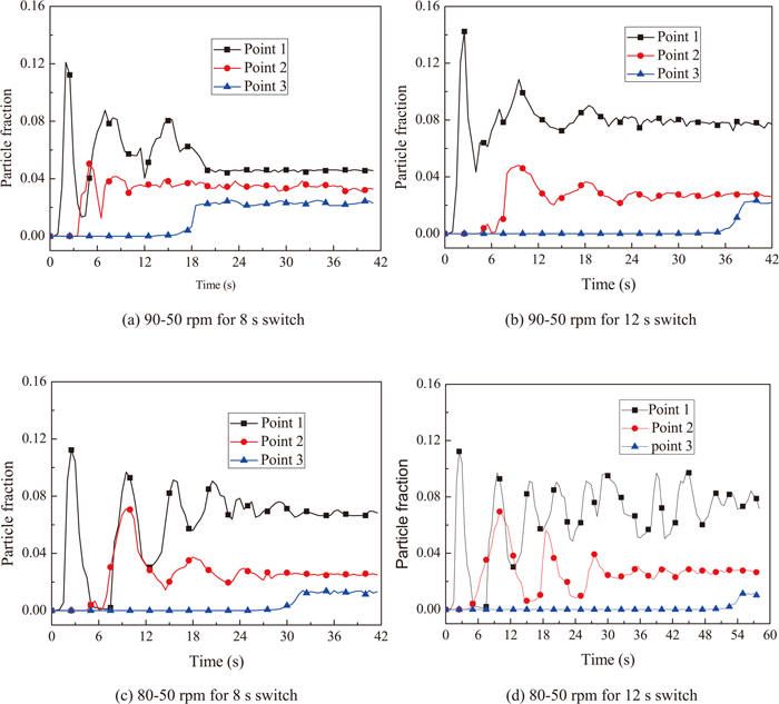
Figure 17 shows the evolution of particle volume fraction at each point under different stirring modes. The initial particle volume fractions at the point 1 and point 2 fluctuate and the value at the point 2 reaches stable state first. The times of fluctuation are short at the large rotation range and the steady state can be reached quickly at the point 1. The hot metal cannot mixes with the desulfurizer in a long time at the point 3. Although the desulfurizer can reach the point 3 at the late stage of stirring, the mixing level is still lower. The short switch time results in shorter mixing time, and larger particle volume fraction can be obtained under the larger rotating range. The mixing time is 20 s under the stirring mode of 90–50 for 8 s switch, which is the shortest mixing time under four stirring modes. The difference of particle volume fraction among three points is the least under the stirring mode of 90–50 for 8 s switch, presenting the uniformity is the best under the stirring mode of 90–50 for 8 s switch. Therefore, it is concluded that the mixing efficiency under the stirring mode of 90–50 for 8 s switch is the highest among four stirring modes.
4. Conclusions
Based on the Euler-granular model, the solid-liquid model was established to describe the mixing behavior of lime and high-sulfur hot metal under the variable-velocity stirring mode for hot metal desulphurization. The effects of switch time and variable velocity range on the entrainment and dispersion of desulfurizer were investigated. An optimization of stirring modes has been proposed based on the consideration of mixing efficiency, power consumption, and torque.
(1) The variable-velocity stirring mode can improve the traditional flow field and increase the entrainment and dispersion of desulfurizer.
(2) Efficiencies of entrainment and dispersion increase with increasing the range of variable velocity or decreasing the switch time.
(3) The variable-velocity switch time has a great influence on the mixing time and the uniform degree of mixing, and the range of variable velocity has a great influence on the value of particle volume fraction.
(4) The stirring mode of 90–50 rpm for 8 s switch is the best choice based on the consideration of mixing efficiency, power consumption, and torque.
Acknowledgement
The present work is supported financially by the National Natural Science Foundation of China under the grants of 51376040 and 11072057.
Nomenclature
I: Unity matrix
M: Torque (N·m)
NMax: Maximum rotation velocity (rpm)
NMin: Minimum rotation velocity (rpm)
P: Power consumption (w)
U: Velocity vector (m/s)
g: Gravity acceleration (m/s2)
l: Liquid phase
p: Pressure (pa)
q: Phase
s: Solid phase
α: Fluid volume fraction,
ρ: Fluid density (Kg/m3)
k: Turbulent kinetic energy (m2/s2)
ε: Energy dissipation rate (m2/s2)
ω: Angular velocity (rad/s)
μl: Liquid phase effective viscosity
μs: Solid phase shear viscosity
λl: Volume viscosity of liquid phase
References
- 1) Z. D. Yang, X. X. Xue, Q. Liu and S. L. Liu: J. Northeast Univ., 30 (2009), 567.
- 2) L. Socha, J. Bazan, K. Gryc, J. Moravka, P. Stymal, V. Pilka and Z. Piegza: Mater. Technol. J., 47 (2013), 673.
- 3) H. B. Li, X. Zhang, J. Cheng and X. G. Fan: Sichuan Metall. J., 36 (2014), 38.
- 4) Y. Deng, Y. H. Ding, J. F. Li, H. P. Zhang and L. M. Zhang: Iron Steel Res. J., 42 (2014), 26.
- 5) A. Z. Luo, D. G. Ouyang, M. H. Li, S. H. Zhu, H. Y. Jiang and H. Q. Wang: Iron Steel Res. J., 40 (2012), 31.
- 6) J. H. Ji, R. Q. Liang, and J. C. He: J. Iron Steel Res. Int., 19 (2012), 171.
- 7) R. Shiba, M. A. Uddin, Y. Kato and S. Kitamura: ISIJ Int., 54 (2014), 2754.
- 8) Y. Nakai, I. Sumi, H. Matsuno, N. Kikuchi and Y. Kishimoto: ISIJ Int., 50 (2010), 403.
- 9) W. Wu, W. Wu, Y. B. Hu, L. Liu and Y. L. Ding: J. Iron Steel Res. Int., 15 (2008), 15.
- 10) K. Wu, Z. G. Liang, E. H. Zhang and H. M. Li: Acta Metall. Sin., 37 (2001), 1069.
- 11) Y. Liu, M. Sano, T. A. Zhang, Q. Wang and J. C. He: ISIJ Int., 49 (2009), 17.
- 12) D. C. Y. Wong, Z. Jaworski and A. W. Nienow: Chem. Eng. Sci., 56 (2001), 727.
- 13) A. Brucato, F. Grissini and G. Montante: Chem. Eng. Sci., 53 (1998), 3295.
- 14) M. Hamidipour, J. W. Chen and F. Larachi: Chem. Eng. Sci., 78 (2012), 167.
- 15) I. Naude, C. Xuereb and J. Bertrand: Can. J. Chem. Eng., 76 (1998), 631.
- 16) G. Montante and F. Magelli: Int. J. Comput. Fluid D, 19 (2005), 253.