Abstract
Accurate knowledge of dislocation reactions is crucial for understanding and controlling the macroscopic mechanical properties of α-iron and its alloys. A dislocation reaction: 1/2[111]+1/2[111]→[110] has never been observed. However, using in-situ transmission electron microscopy, we demonstrate that the two nanoscale 1/2<111> prismatic dislocation loops that undergo 1D glide motion approach and collide with each other to form a “high-energy” [110]-dislocation junction. This anomalous reaction cannot be understood within the framework of the elasticity.
1. Introduction
Reactions between two dislocations are key processes for understanding and controlling the dislocation-microstructure evolution in crystalline materials under plastic deformation, which governs the macroscopic mechanical properties.1)
In α-iron and its alloys with the body-centered cubic (bcc) structure, only perfect dislocations with the Burgers vector, b, being equivalent to a unit lattice vector can be present, to avoid the presence of the high-energy stacking fault.2) The most major perfect dislocations are ones with b = 1/2<111>. This can be simply interpreted even within the framework of the isotropic elasticity. The isotropic elastic self-energy for a straight dislocation per unit length, Eiso, is given by
|
E
iso
≈
μ
4π
[
(
b⋅ξ
)
2
+
|
(
b×ξ
)
|
2
1-ν
]ln
R
r
0
,
| (1) |
where
μ,
ξ,
ν,
R,
r0 are the shear modulus, dislocation line direction, Poisson’s ratio, effective specimen size, and dislocation core radius, respectively.
2) Thus, because
Eiso is proportional to
b2, the
Eiso value is the lowest for the 1/2<111> dislocations with the smallest
b value. However, the “high-energy” <100> and <110> dislocations with larger
b values have been also observed in deformed
α-iron by transmission electron microscopy (TEM)
3) and field-ion microscopy.
4) These “high-energy” <100> and <110> dislocations can be interpreted to be formed by the following dislocation reactions, which do not increase the total
Eiso values:
|
1/2[111]+1/2[1
1
¯
1
¯
]→[100]
| (2) |
On the other hand, it appears that <110> dislocations cannot be formed by the following direct reaction between two 1/2<111>:
|
1/2[111]+1/2[11
1
¯
]→[110],
| (4) |
because this reaction increases the total
Eiso value. To the best of our knowledge, this reaction given by
Eq. (4) has never been observed. In the present study, using in-situ TEM, we show that the two 1/2<111> dislocations can collide with each other to form a <110> dislocation, for the first time.
The objects which we observed in this study are nanoscale prismatic dislocation loops,2) which are planar clusters of point defects (self-interstitial atoms (SIAs) and vacancies). Loops are ubiquitous lattice defects, which are produced in crystalline materials upon energetic particle irradiation, plastic deformation, and quenching. Therefore, for understanding and controlling these processes, accurate knowledge on dynamic behaviors of loops is required.
In α-iron, it has been revealed by molecular dynamics (MD) simulations5,6,7,8,9) and in-situ TEM experiments,10,11,12) nanoscale interstitial-type prismatic dislocation loops with b = 1/2<111> undergo one-dimensional (1D) glide diffusion (Brownian motion) along their b directions by thermal energy even in the absence of stresses. Two 1D migrating 1/2<111> loops with different b values and intersecting glide cylinders can collide with each other, via attractive elastic interaction,13) which has been shown by MD simulations14,15,16,17) and an in-situ TEM experiment.18) According to these studies,14,15,16,17,18) a 1/2[111] loop (loop A) basically collides with a 1/2[1 11] loop (loop B) side by side, to form a dislocation junction. After the junction formation, the loop complex transforms to a single loop with a single b value through dislocation reactions within the loop complex.14,15,16,17,18) From a simple geometrical consideration, b value of the junction can be [001] or [110], with depending on the facing sides for the loop collision.19) So far, only the [001]-junction formation via the loop collision was found; however, the [110]-junction formation was not found.14,15,16,17,18) In this study, using in-situ TEM, we show the process of the collision between loops A and B for the [110]-junction formation.
2. Experimental Procedures
The experimental procedures in the present study is similar to that in our previous study, where the [100]-junction formation via the collision between loops A and B was observed, using in-situ TEM.18)
Polycrystalline α-iron (purity: 99.998 wt.%, residual resistivity ratio: 2200) was used as the specimen. It was rolled into a 0.08-mm-thick sheet. These sheets were pre-annealed at 1073 K for 2 h under a hydrogen atmosphere and electrochemically polished for TEM. Crystalline grains larger than approximately 100 μm in diameter with the surfaces of approximately (110) plane were selected for the experiment. Thus, the b values of loops A and B were almost parallel to the surfaces; therefore, the force (i.e., image force) applied to the loops from the surfaces in the direction of the 1D motion was negligible.
Nanoscale interstitial-type 1/2<111> prismatic dislocation loops were produced via the agglomeration of SIAs generated by the knock-on displacement of host atoms upon 2000 keV electron irradiation in a high-voltage electron microscope H-3000 (Hitachi). The irradiation was performed with a beam flux of 1 × 10²³ e–/m2s to a dose of 3 × 1025 e–/m2 at approximately 150 K.
We tried to find the loop collision for the [110]-junction formation by in-situ TEM observations of the behavior of 1/2<111> loops undergoing 1D motion10) under simple heating within a conventional microscope H-800 (Hitachi), at an acceleration voltage of 200 kV in order to prevent the introduction of additional knock-on displacements into the specimens. The beam diameter was approximately 8 μm, and the beam flux was approximately 5 × 10²⁰ e–/m2s. Then, the effect of thermal stress due to beam heating on the loop motion was negligible. The temperature ranged from 290 K to 800 K. Bright-field imaging20) was used in the in situ TEM observations. The thickness of the areas observed was less than approximately 100 nm. The observation axis was approximately [110]. The refiections adopted were g =110 and g = 002, with a deviation parameter from the exact Bragg conditions ranging from 0.02 to 0.06 /nm. The images were recorded using a silicon intensifier target tube camera with a time resolution of 1/30 s. The b value of each loop could be determined from the direction of its 1D motion.
3. Experimental Results
Figure 1 displays a series of sequential micrographs showing the collision between two loops and the subsequent reaction at 700 K. From the directions of 1D motion of the two loops before the collision, the b values of loops A and B are determined as bA = 1/2[111] and bB = 1/2[1 11], respectively. At 3.09 s, loops collide with each other side by side and form a junction. Even after the formation of the junction, the reaction is not finalized and progresses further. The junction moves toward the far end of loop A, and a single loop is finally formed at 45.93 s. The b value of the final single loop is identical to that of the original loop B, as determined by its direction of motion. This shows that loop B absorbed loop A.

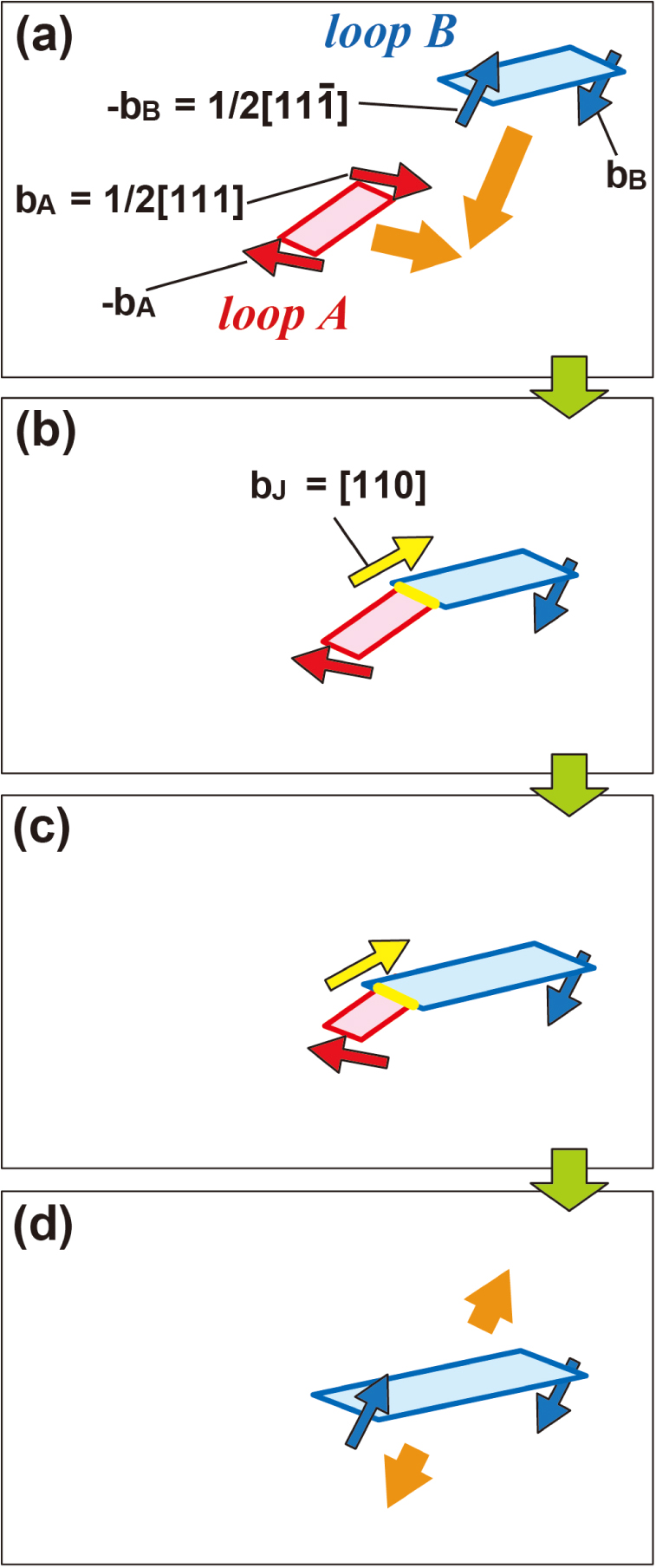
Figure 2 shows a schematic view of the process displayed in Fig. 1. In Fig. 2, for simplicity, the shape of the loops is approximated as squares or rectangles. Here, the segments parallel to the junction, which is approximately parallel to the direction of the view, are noticed. A group of these segments could be regarded as multi-poles. The dislocation line directions are set to be from the near to the far side. Then, the direction of the b value of each segment was determined by the FS/RH convention.2) From the b values of the two segments at which loops are colliding, the b value of the junction formed by the collision, bJ, is determined as bJ = bA + (−bB) = [110].
The absorption of loop A by loop B is completed through the reaction between the junction and the end of loop A: bJ + (−bA) = −bB. The loop complex itself which involves the junction is essentially sessile; however, it is converted to a single glissile loop by the absorption reaction.
It is noted that some MD studies proposed that a [001] loop can be formed via the collision between loops A and B,15,17) and another MD study did not reproduce this process.16) On the other hand, it was pointed out based on the conventional dislocation theory that the [110]-junction formation is necessary to the formation of a single [001] loop via the collision between loops A and B.19) The present experimental result shows that one loop absorbs another one even in the case of the [110]-junction formation, like the case of the [001]-junction formation.18)
4. Discussion
We consider the origin of the attractive interaction and collision between loops A and B even for the “high-energy” [110]-junction formation.
We firstly consider the elastic self-energy of long straight dislocations. The dislocation reaction given by Eq. (4) increases the total isotropic self-energy (Eq. (1)) by a factor of 4/3 (approximately 1.3). We evaluated this factor, using anisotropic elasticity21) being more accurate than isotropic elasticity. It is noted that in α-iron the anisotropic elastic self-energy depends on temperature because the elastic constants, C11, C12, and C14, considerably depend on temperature.22) However, within the temperature range from 298 to 1173 K where the elastic constants was provided,22) this factor was larger than unity. For example, at 700 K as in the case of Fig. 1, this factor for a [110] dislocation with [110] line and 1/2[111] straight dislocations with the same line was approximately 1.4, which was close to the value obtained by isotropic elasticity. Thus, for straight dislocations, it appears that even anisotropic elasticity cannot resolve the origin of the [110]-junction formation via the collision between the two 1/2<111> dislocations.
Next, we considered the effect of small dislocation “loops” with segments with the opposite-sign b. Here, we tried to find the path for the loop collision that reduces the total energy, and we calculated the isotropic interaction energy between the two loops. The isotropic interaction energy between loop 1 with b1 and loop 2 with b2, W12, is given by2)
|
W
12
=-
μ
2π
∮
C
1
∮
C
2
(
b
1
×
b
2
)
⋅(
d
l
1
×d
l
2
)
R
+
μ
4π
∮
C
1
∮
C
2
(
b
1
⋅d
l
1
)
⋅(
b
2
⋅d
l
2
)
R
+
μ
4π(1-ν)
∮
C
1
∮
C
2
(
b
1
×d
l
1
)
⋅T⋅(
b
2
×d
l
2
)
,
| (5) |
where
R is the distance between line elements
dl1 of loop 1 and
dl2 of loop 2, and
T is a tensor with the components of
T
ij
=
∂
2
R
∂
x
i
∂
x
j
. We executed the numerical integration of
Eq. (5) for loops A and B. Here,
x,
y, and
z axes in the coordinate system were set to be in the direction of [
1 1 2], [1
10], and [
1 11], respectively. The mass center of loop B was located at the origin, and that of loop A was located at position (
x,
y,
z). Thus, the
W12 value is regarded as the function of the relative mass-center position of loop A to loop B. Hereafter, we show the results of the cases where the shape of the two loops is a circle with a radius of 5 nm and the mass centers of the two loops is limited within a (1
10) plane (
y = 0).
Figure 3 shows the result for the pure edge-dislocation loops whose habit planes are perfectly normal to the b values. The points marked with “X” correspond to the side-by-side collision between the two loops and the formation of <001> or <110> junction. It is noted that the relative position of loop A to loop B can “move” along this path only by the 1D glide motion of both loops A and B in the b directions. There are paths for the <001> junction formation which does not increase the W12 value, as shown by the arrows. However, there are no paths for the [110] junction formation. Next, we tried the mixed dislocation loops whose habit planes were inclined to the b values. The “inclination” of the loop habit plane is rationalized because screw dislocations basically have lower elastic energies than edge dislocations (Eq. (1)). Also, the loop-plane inclination was confirmed by TEM.11,18) We have tried various habit planes for the two loops to find the path for the [110]-junction formation. The W12 values considerably depended on the habit planes. Figure 4 shows a result, where both the habit planes of loops A and B were set to be (001). In this case, the <100>-junction formation is geometrically forbidden. Interestingly, there are paths that the loop A can approach loop B until just before their collision for the <110>-junction formation, which do not increase the W12 values. However, the nearby two loops cannot collide with each other for the formation of the <110> junction. Thus, even in the consideration of the loop-shape effect, it appears that the <110>-junction formation could not be understood within the framework of the elasticity. Further theoretical studies will be required.

5. Conclusions
Using in-situ TEM, in α-iron under heating, we demonstrated that the two nanoscale 1/2<111> prismatic dislocation loops that undergo 1D glide motion approach and collide with each other to form a “high-energy” [110]-dislocation junction. We confirmed that the origin of this anomalous dislocation reaction: 1/2[111]+1/2[111]→[110] cannot be understood within the framework of elasticity. The result obtained in this study will be useful for understanding the processes where loops with a high density are produced, such as heavy plastic deformation and energetic particle irradiation.
Acknowledgements
We thank Mr. T. Yasuda at Research Center for Ultra-High Voltage Electron Microscopy in Osaka University for his technical support of our experiments with H-3000. This work was financially supported by Grants-in-Aid for Scientific Research (Grant No. 15H04244 and 15K14109) from Japan Society for the Promotion of Science, and the Iron and Steel Institute of Japan Research Promotion Grant. Part of this work was supported by the “Advanced Characterization Nanotechnology Platform, Nanotechnology Platform Programs” of the Ministry of Education, Culture, Sports, Science and Technology (MEXT), Japan, at Research Center for Ultra-High Voltage Electron Microscopy (Nanotechnology Open Facilities) in Osaka University, and TATARA Nanotechnology Project Center in Shimane University.
References
- 1) A. S. Argon: Strengthening Mechanisms in Crystal Plasticity, Oxford University Press, Oxford, (2008).
- 2) J. P. Hirth and J. Lothe: Theory of Dislocations, Wiley, New York, (1982).
- 3) D. J. Dingley and K. F. Hale: Burgers Vectors of Dislocations in Deformed Iron and Iron Alloys. Proc. R. Soc. Lond. A, 295 (1966), 55.
- 4) D. A. Smith, R. Morgan and B. Ralph: Philos. Mag., 18 (1968), 869.
- 5) B. D. Wirth, G. R. Odette, D. Maroudas and G. E. Lucas: J. Nucl. Mater., 276 (2000), 33.
- 6) N. Soneda and T. Diaz de La Rubia: Philos. Mag. A, 81 (2001), 331.
- 7) J. Marian, B. D. Wirth, A. Caro, B. Sadigh, G. R. Odette, J. M. Perlado and T. Diaz de la Rubia: Phys. Rev. B, 65 (2002), 144102.
- 8) Y. N. Osetsky, D. J. Bacon, A. Serra, B. N. Singh and S. I. Golubov: Philos. Mag., 83 (2003), 61.
- 9) D. A. Terentyev, L. Malerba and M. Hou: Phys. Rev. B., 75 (2007), 13.
- 10) K. Arakawa, K. Ono, M. Isshiki, K. Mimura, M. Uchikoshi and H. Mori: Science, 318 (2007), 956.
- 11) Z. Yao, M. L. Jenkins, M. Hernández-Mayoral and M. A. Kirk: Philos. Mag., 90 (2010), 4623.
- 12) K. Arakawa, T. Amino and H. Mori: ISIJ Int., 54 (2014), 2421.
- 13) S. L. Dudarev, K. Arakawa, X. Yi, Z. Yao, M. L. Jenkins, M. R. Gilbert and P. M. Derlet: J. Nucl. Mater., 455 (2014), 16.
- 14) Y. N. Osetsky, A. Serra and V. Priego: J. Nucl. Mater., 276 (2000), 202.
- 15) J. Marian, B. D. Wirth and J. M. Perlado: Phys. Rev. Lett., 88 (2002), 255507.
- 16) D. Terentyev, L. Malerba, P. Klaver and P. Olsson: J. Nucl. Mater., 382 (2008), 126.
- 17) H. Xu, R. E. Stoller, Y. N. Osetsky and D. Terentyev: Phys. Rev. Lett., 110 (2013), 265503.
- 18) K. Arakawa, T. Amino and H. Mori: Acta Mater., 59 (2011), 141.
- 19) K. Arakawa and H. Mori: J. Phys.: Conf. Ser., 165 (2009), 012005.
- 20) M. L. Jenkins and M. A. Kirk: Characterization of Radiation Damage by Transmission Electron Microscopy, Institute of Physics, Bristol and Philadelphia, (2001).
- 21) D. J. Bacon, D. M. Barnett and R. O. Scattergood: Prog. Mater. Sci., 23 (1980), 51.
- 22) D. J. Dever: J. Appl. Phys., 43 (1972), 3293.