4. Discussions
4.1. Kinetic Model of Slag-Metal Reactions
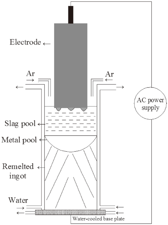
In order to better clarify the variation mechanism, the slag-metal reactions were investigated from the viewpoint of kinetics. The ESR system is a complex metallurgical process involving different reaction interfaces, electrode tip-slag interface, droplet-slag interface, metal pool-slag interface, respectively.9) The kinetic model is based on mass transfer control across the slag-metal interface at which equilibrium is maintained during ESR process. The following assumptions are considered in this model.
(1) At each reaction position, the slag-metal system is considered to consist of two semi-infinite systems.
(2) In the two phases of slag and metal, the initial concentrations of reactants and products are evenly distributed.
(3) The coupled reactions at the slag-metal interface occur quickly, and reach up to a total chemical equilibrium state. The rate of reactions is controlled by the diffusion of reactants and products through a boundary layer at the reacting interface.
(4) The effective segregation coefficient at liquid pool/ingot interface is equal to one and no further chemical refining occurs after solidification.
The coupled reactions occurred at different slag-metal interfaces are expressed as Eqs. (2), (3), (4), (5):
|
[Al]+1.5[O]=(Al
O
1.5
)
| (2) |
The expressions of standard equilibrium constants of Eqs.(2), (3), (4), (5) are given as Eqs. (6), (7), (8), (9):
|
lgK
Al
θ
=
32 000
T
-10.29
| (6) 10) |
|
lgK
Si
θ
=
30 410
T
-11.59
| (7) 11) |
|
lgK
Mn
θ
=
15 015
T
-6.664
| (8) 10,12) |
|
lgK
Fe
θ
=
6 320
T
-2.734
| (9) 13) |
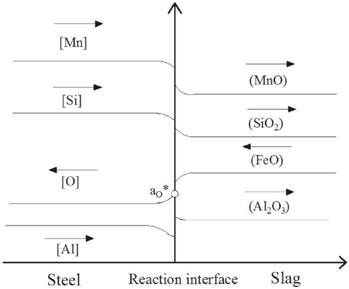
All the reactants and products can be classified into four systems Al+Al2O3, Si+SiO2, Mn+MnO, Fe+FeO. During the refining process, the concentration of different components changes continuously, with the corresponding material flow across the slag-metal interface, as shown in Fig. 3.
The following equation represents the flux of metal element i into the slag, as the form of iOx.
|
J
i
=
k
i, m
ρ
m
100
M
i
{
[%i]-[%i]*
}
=
k
i, s
ρ
s
100
M
i
O
x
{
(%i
O
x
)*-(%i
O
x
)
}
| (10) |
Where Ji is the molar flow, mol.cm−2.s−1. ki,m and ki,s represent the mass transfer coefficient for component in molten steel and slag, cm.s−1. Mi and
M
i
O
x
is molecular weight of steel and slag components, g.mol−1. ρm andρs is the density of steel and slag, 7.20 g.cm−3 and 2.65 g.cm−3, respectively. A symbol with superscript (*) represents an interfacial concentration.
According to Eq. (10), the equilibrium concentration of metal element at the interface can be re-arranged as follows.
|
[%i]*=
k
i,m
ρ
m
M
i
O
x
M
i
k
i,s
ρ
s
[%i]+(%i
O
x
)
B
i
(
a
O
*
)
x
+
k
i,m
ρ
m
M
i
O
x
M
i
k
i,s
ρ
s
| (11) |
Where Bi is the apparent equilibrium constant, which is expressed as Eq. (12):
|
B
i
=
(%i
O
x
)*
[%i]*
(
a
O
*)
x
=
M
i
O
x
f
M
K
M
{
(%
CaF
2
)
M
CaF
2
+∑
(%i
O
x
)
M
i
O
x
}
γ
i
O
x
| (12) |
Where aO* is the oxygen activity at the interface. KM is the equilibrium constant, fM is the Henry activity coefficient,
γ
i
O
x
is the Raoult activity coefficient of slag component which are given as Eqs. (13), (14), (15), (16):14)
|
lg
γ
FeO
=
11 800
T
(
N
CaO
+
N
MgO
)(
N
SiO
2
+0.25
N
AlO
1.5
)
+
4 916
T
N
MnO
N
SiO
2
+
3 562
T
N
AlO
1.5
N
SiO
2
+
123
T
N
MnO
N
AlO
1.5
| (13) |
|
lg
γ
MnO
=lg
γ
FeO
-
4 916
T
N
Si
O
2
-
123
T
N
Al
O
1.5
| (14) |
|
lg
γ
Si
O
2
=lg
γ
FeO
-
11 800
T
(
N
CaO
+
N
MgO
)
-
4 916
T
N
MnO
-
3 562
T
N
Al
O
1.5
| (15) |
|
lg
γ
AlO1.5
=lg
γ
FeO
-
2 950
T
(
N
CaO
+
N
MgO
)
-
3 562
T
N
Si
O
2
+
123
T
N
MgO
| (16) |
Here, Ni is the mole fraction of component in the molten slag.
The reaction rate of respective component can be given as Eq. (17):
|
-
d[%i]
dt
=
A⋅
k
i,m
V
m
⋅
ρ
m
100
M
i
([%i]-[%i]*)
| (17) |
A, Vm are the reaction area, cm2 and volume of molten steel, cm3. Combining Eqs. (11), (12) and (17), the final expression of reaction rate can be re-arranged as follows.
|
-
d[%Al]
dt
=
A
W
m
⋅
k
Al
⋅{
[%Al]-
(%Al
O
1.5
)
B
Al
(
a
O
*)
1.5
}
| (18) |
|
1
k
Al
=
1
ρ
m
k
Al,m
+
M
Al
O
1.5
B
Al
M
Al
ρ
s
(
a
O
*)
1.5
k
Al
O
1.5
| (19) |
|
-
d[%Si]
dt
=
A
W
m
⋅
k
Si
⋅{
[%Si]-
(%Si
O
2
)
B
Si
(
a
O
*)
2
}
| (20) |
|
1
k
Si
=
1
ρ
m
k
Si,m
+
M
Si
O
2
B
Si
M
Si
ρ
s
(
a
O
*)
2
k
Si
O
2
| (21) |
|
-
d[%Mn]
dt
=
A
W
m
⋅
k
Mn
⋅{
[%Mn]-
(%MnO)
B
Mn
a
O
*
}
| (22) |
|
1
k
Mn
=
1
ρ
m
k
Mn,m
+
M
MnO
B
Mn
M
Mn
ρ
s
a
O
*
k
MnO
| (23) |
|
-
d[%O]
dt
=
A
W
m
⋅
k
O
⋅{
(%FeO)
B
Fe
a
O
*
-[%O]
}
| (24) |
|
1
k
O
=
1
ρ
m
k
O,m
+
M
FeO
B
Fe
M
O
ρ
s
a
O
*
k
FeO
| (25) |
Here, Wm is the mass of molten steel, ki is the overall mass transfer coefficient. The oxygen activity at the interface can be determined on the basis of the mass balance of elements across the interface.
|
1.5
M
Al
⋅
d[%Al]
dt
+
2
M
Si
⋅
d[%Si]
dt
+
1
M
Mn
⋅
d[%Mn]
dt
-
1
M
O
⋅
d[%O]
dt
=0
| (26) |
The Eqs. (18), (19), (20), (21), (22), (23), (24), (25), (26) are applicable at all the slag/metal interfaces. When the oxygen activity at interface and mass transfer coefficients are given, the reaction rate of respective component can be obtained.
4.1.1. Mass Transfer Coefficient
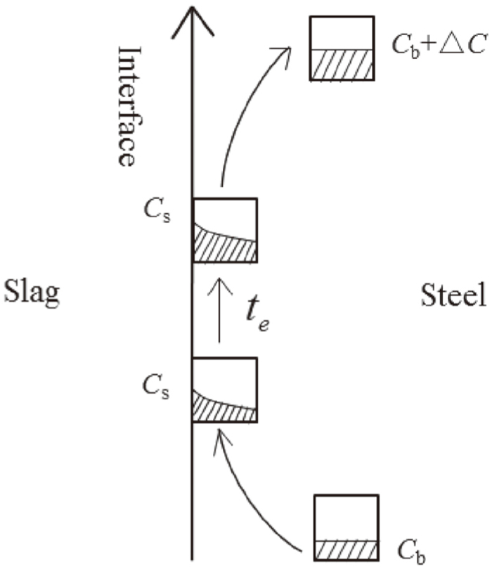
The penetration theory is used to calculate the mass transfer coefficient both in molten steel and slag which assumes that interface is continuously renewed by eddies of fresh material from bulk liquid.8) Figure 4 shows the schematic diagram of flow of fluid element at the metal side.
(1) Mass Transfer at the Metal Film/slag Interface
At the metal film side, the mass transfer coefficients of metal element can be calculated by Eq. (27):
Where Di is the diffusion coefficient, cm2.s−1, te is the time that an eddy is in contact with the interface which can be obtained through Eq. (28):15)
|
t
e
=3.35
(
2πcosθ
3
Q
m
)
2/3
(
μ
m
g
ρ
m
sinθ
)
1/3
(
R
E
cosθ
)
5/3
| (28) |
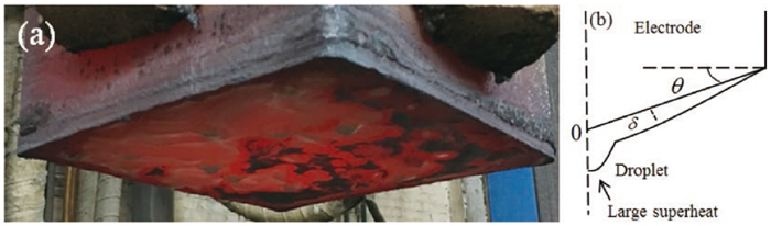
Where θ is angle of cone. Qm is the rate of volumetric melting, cm3.s−1. RE is the equivalent radius of electrode, μm is the viscosity of metal in 0.005 Pa.s−1. In order to determine the cone angle, the electrode was quickly lifted during the refining process, as shown in Fig. 5(a). It can be seen that there are several small droplets generate simultaneously at the electrode tip. It is assumed that the time of every small droplet stay at the electrode tip is the same. The cone angle is set as 10°, as shown in schematic diagram of the electrode tip Fig. 5(b). After being calculated, the contact time during the droplet formation is about 2.89 s.
The behavior of mass transfer has a strong dependence of temperature. It has been reported that the temperature of metal film at electrode tip is close to the liquidus temperature of steel (1785 K, calculated by Thermo-Calc software), and its superheat cannot exceed 20–30 K.16,17) Thus, the temperature of metal film is supposed to be 1815 K more or less. It was assumed that the diffusion coefficient Di has an identical value of 6.10×10⁻⁵ cm2.s−1 at 1815 K for Al, Si, Mn and oxygen.11) After calculation, ki is 0.0091 cm.s−1 for the element at the metal film.
At the slag side, at a velocity of about 10 cm.s−1, the contact time is about 0.70 s. The diffusion coefficient of Al2O3, SiO2 is 1.00×10⁻⁵ cm2.s−1 while MnO and FeO is 4.00×10⁻⁵ cm2.s−1.11) Therefore, ki is 0.0037 cm.s−1 for Al2O3 and SiO2, 0.0074 cm.s−1 for MnO and FeO.
As mentioned above, the droplets generate in several sites, in this case, the composition of metal film will be rather uniform and close to that of droplets at the electrode tip except the soluble oxygen, for that the droplet was heated continuously to a high temperature about 1973 K by the molten slag within 2.89 seconds. Therefore, the dissolvability of oxygen will increase obviously. It is assumed that the mass transfer coefficient of oxygen at metal side is 0.030 cm. s−1.
(2) Mass Transfer at the Falling Droplet/slag Interface and Metal Pool/slag Interface
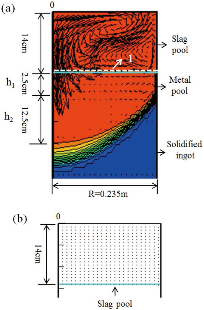
The average temperature of slag pool and metal pool/slag interface is determined by commercial software Meltflow-ESR. All the related parameters including the properties of slag and steel, refining time, secondary voltage and alternate current used in the experimental are input the preprocessing software, after calculation, the results can be output by Tecplot Focus. Figure 6(a) shows the velocity and temperature fields. The black line in the slag pool represents the velocity. The more intensive the line, the higher the velocity is. The average temperature of 437 points in Fig. 6(b) is utilized to evaluate the temperature of slag pool. The white vector represents the slag/metal pool interface. Extract the temperature of “Path 1” (slag pool/metal pool interface), then, take the average. The average temperature of slag pool and metal pool/slag interface is 2020 K, 1957 K, respectively.
At the metal side, the diffusion coefficient of Al, Si, Mn and O at 2020 K is 1.93×10⁻³ cm2.s−1 while 1.34×10⁻³ cm2.s−1 at 1957 K.11) The velocity of droplet falling is set as 61 cm.s−1, and the time of droplet falling is about 0.23 s. According to the penetration theory, ki is 0.10 cm.s−1 at the droplet and 0.018 cm.s−1 in the metal pool.
At the slag side, the diffusion coefficient of Al2O3, SiO2 is 9.00×10⁻⁵ cm2.s−1 at 2020 K, 7.00×10⁻⁵ cm2.s−1 at 1957 K, while MnO and FeO is 1.20×10⁻⁴ cm2.s−1 at 2020 K, 1.00×10⁻⁴ cm2.s−1 at 1957 K.11) After calculation, ki is 0.022 cm.s−1 for Al2O3 and SiO2, 0.026 cm.s−1 for MnO and FeO during the falling of droplet, while 0.0042 cm.s−1 for Al2O3 and SiO2, 0.0050 cm.s−1 for MnO and FeO at the slag side.
4.1.2. Area/Volume Ratio Estimates
(1) Area/volume Ratio of Metal Film
At the metal film/slag interface, the area and volume of metal film is estimated from Eqs. (29) and (30):
|
A
Film
=
π
R
E
2
cosθ
=731.42
cm
2
| (29) |
|
V
Film
=
π
R
E
2
δ
¯
3
=10.59
cm
3
| (30) |
Where
δ
¯
is the average thickness of metal film, which can be calculated from Eq. (31):15)
|
δ
¯
=
[
3
μ
m
Q
m
2π(
ρ
m
-
ρ
S
)gsinθcosθ
(
1-
x
2
cos
2
θ
R
E
2
)
]
1/3
| (31) |
(2) Area/volume Ratio of Droplet and Metal Pool
During the time of droplet falling, because of the oscillation effect, it was assumed that area/volume ratio is about 24.0.8) The metal pool is constituted of a cylinder and cone, as shown in Fig. 6(a). The depth of cylinder h1 is 2.5 cm and the cone h2 is 12.5 cm. Thus, the area and volume of metal pool can be obtained as follows.
|
A
Metal Pool
=π
R
M
2
=1 734
cm
2
| (32) |
|
V
Metal Pool
=
V
Cylinder
+
V
Cone
=π
R
M
2
h
1
+
π
R
M
2
h
2
3
=11 560
cm
3
| (33) |
Where RM is the radius of mold, cm.
In light of the above analysis, all the necessary parameters for use in the model have been detailed, as listed in Table 4.
Table 4. The related parameters used in the model.
| Parameter | Metal film | Droplet | Metal pool |
|---|
| kAl, cm/s | 0.0091 | 0.10 | 0.018 |
|
k
Al
2
O
3
, cm/s
| 0.0037 | 0.022 | 0.0042 |
| kSi, cm/s | 0.0091 | 0.10 | 0.018 |
|
k
SiO
2
,cm/s
| 0.0037 | 0.022 | 0.0042 |
| kMn, cm/s | 0.0091 | 0.10 | 0.018 |
| kMnO, cm/s | 0.0074 | 0.026 | 0.0050 |
| kO, cm/s | 0.0091 | 0.10 | 0.018 |
| kFeO, cm/s | 0.0074 | 0.026 | 0.0050 |
| Temperature/K | 1815 | 2020 | 1957 |
| Am/Vm | 70 | 24 | 0.15 |
| Residence time, s | 2.89 | 0.23 | – |
Table 5 shows the apparent equilibrium constants of reactions (2) and (5) at the beginning of refining. It indicates that the value of BAl is several orders of magnitude higher than BFe. Table 6 shows the mass transfer resistance of element in steel and slag. It can be seen that the rate-determining step of Al-oxidation is on the metal side while oxygen increase lies in the slag phase transport, which is closely related with the value of BM. The mass transfer resistance includes BM in the denominator. With the value of BM decreasing, the resistance shows a rising trend. Therefore, the high mass transfer resistance of FeO is mainly due to the low value of the apparent equilibrium constant BFe. In addition, with the temperature increasing, the mass transfer resistance of all elements decreases obviously.
Table 5. Apparent equilibrium constants of reactions (2) and (5) at the beginning of refining.
| Location | BAl | BFe |
|---|
| Metal film | 6.53×10⁸ | 314 |
| Droplet | 3.73×10⁷ | 178 |
| Metal pool | 8.25×10⁷ | 209 |
Table 6. Mass transfer resistance of element in steel and slag.
| Remelting stage | Location | Mass transfer resistance in steel | Mass transfer resistance of AlO1.5 | Mass transfer resistance of FeO |
|---|
|
1
ρ
m
k
m
|
M
Al
O
1.5
B
Al
M
Al
ρ
s
(
a
O
*)
1.5
k
Al
O
1.5
|
M
FeO
B
Fe
M
O
ρ
s
a
O
*
k
FeO
|
|---|
| Beginning | Metal film | 9.09 | 0.084 | 3942.95 |
| Droplet | 1.35 | 0.041 | 481.10 |
| Metal pool | 7.69 | 0.18 | 3292.94 |
| End | Metal film | 9.09 | 0.036 | 2240.80 |
| Droplet | 1.35 | 0.023 | 332.28 |
| Metal pool | 7.69 | 0.10 | 2260.45 |
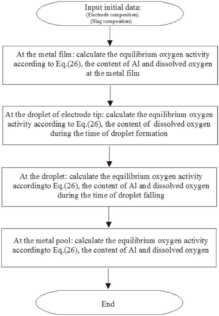
Figure 7 shows the flow chart of the model. The volume element of liquid travels sequentially through various reaction regions, reacting during certain residence time. According to the penetration and film theories, the equilibrium oxygen activity, the content of Al and soluble oxygen with the changing of time at the metal film, droplet, metal pool/slag interface are calculated by Matlab software, respectively.
4.2. Kinetic Analysis
4.2.1. Effect of Oxygen Potential of Slag on the Variation of Al and Soluble Oxygen
The rate-determining step of the oxidation of Al is the mass transfer of Al at the metal side, as shown in Table 6, and the oxidation rate of Al at different slag/metal interfaces can be deduced by the following equation.
|
-
d[%Al]
dt
=
A⋅
k
Al,m
V
m
⋅
ρ
m
100
M
Al
([%Al]-[%Al]*)
| (34) |
From this equation, it indicates that the oxidation rate of Al depends on the Al concentration at the interface [%Al]*, which is determined by the activity of Al2O3 and the equilibrium oxygen activity at the interface.
Thus, the mass concentration of Al changing with time can be obtained by Eq. (35):
|
ln
[%Al]
0
-[%Al]*
[%Al]
t
-[%Al]*
=
A⋅
k
Al,m
V
m
⋅
ρ
m
100
M
Al
t
| (35) |
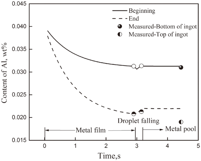
Figure 8 shows the calculated results of the variation of Al from metal film to metal pool, and the measured values in the ingot. The calculated result shows satisfactory agreement with the measured values. At the beginning of refining, the model predicts that the content of Al decreases from 0.040 wt% in the electrode to 0.031 wt% at the metal film, and slightly changed after the droplet detaching from the electrode tip. It is indicated that a very minor role is played by the droplets and metal pool in the overall contribution to the mass transfer of Al. This confirms the evidence of Wei et al.18) which indicates that the metal film was of significance in determining the overall rate of mass transfer.
Al is mainly oxidized by FeO at the metal film due to large area/volume ratio of 70.0, and relatively long contact time of 2.89 s. In order to verify the prediction, the characteristic of inclusions in the droplet as shown in Fig. 5(a) was investigated by SEM-EDS. The result shows that most of the inclusions are newly-generated Al2O3 inclusions, which is different from the globular CaO–MgO–Al2O3 inclusions in the electrode, providing evidence that Al-oxidation has occurred during the time of droplet formation.
At the end of refining, the model indicates that the content of Al decreases from 0.040 wt% in the electrode to 0.021 wt% at the metal film. That is because with the content of FeO in the slag increasing from 0.20 wt% to 0.45 wt%, the equilibrium oxygen activity at the interface increases apparently. Correspondingly, the content of equilibrium Al becomes low, thus enhancing the diffusion of Al from metal to the interface.
If the oxygen activity at interface is obtained, the rate of oxygen increase in the molten steel can be expressed as the following equation.
|
-
d[%O]
dt
=
A⋅
k
O,m
V
m
⋅
ρ
m
100
M
O
([%O]*-[%O])
| (36) |
The mass concentration of oxygen changing with time can be expressed as Eq. (37):
|
ln
[%O]*-
[%O]
0
[%O]*-
[%O]
t
=
A⋅
k
O,m
V
m
⋅
ρ
m
100
M
O
t
| (37) |
Figure 9 shows the calculated results of the variation of soluble oxygen at different locations. At the beginning of refining, the content of soluble oxygen in the droplet of electrode tip is supposed to be 4.30 ppm, about two twice the content at the metal film within 2.89 seconds. This can be explained by the fact that the temperature of droplet is much higher than that at the film. After the droplet detaching from the electrode tip, the content of soluble oxygen continues to rise from 4.30 ppm to 6.80 ppm within 0.23 s. During this period, the content of Al has no tendency to decrease, thus, the high temperature of slag pool is the key factor leading to the pick-up of soluble oxygen. After the droplet falling into the metal pool, the content of soluble oxygen varies little. It is rather difficult to measure the oxygen activity directly, but under such a high temperature, the equilibrium oxygen activity at the interface is definitely very high.
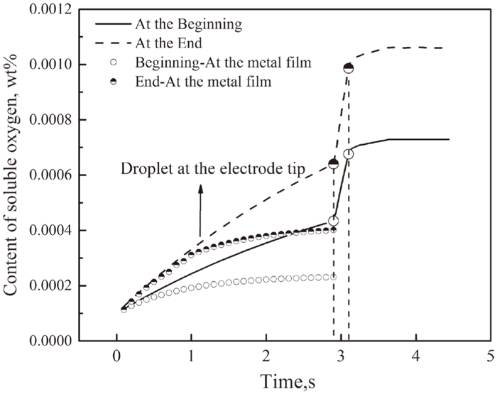
During the last stage of refining, the model indicates that the content of soluble oxygen increase from 6.40 ppm in the droplet of electrode tip to 9.86 ppm during the falling of droplet, much higher than that at the beginning of refining. This can be explained that with the content of FeO increases, the mass transfer resistance shows a downtrend, as shown in Table 5. Therefore, the equilibrium oxygen activity at the interface subsequently increases.
4.2.2. Effect of Al Content in the Electrode and Temperature of Slag Pool on the Variation of Soluble Oxygen
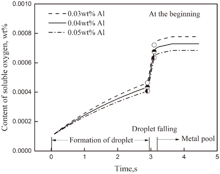
During the industrial ESR process, in order to prevent the excessive oxidation of Al, one method is to improve the Al content of the electrode. Figure 10 shows the effect of Al content in the electrode on the content of soluble oxygen. From Fig. 10, with the content of Al in electrode increasing from 0.030 wt% to 0.050 wt%, the content of soluble oxygen in the metal pool has a limited decrease. Table 6 indicates that the rate-determining step of oxygen increase lies in the mass transfer of FeO at slag side, as given in Eq. (38).
|
-
d[%O]
dt
=
A
W
s
⋅
k
FeO
⋅{
(%FeO)-
B
Fe
a
O
*
}
| (38) |
That is to say, the content of soluble oxygen is influenced more by the oxygen potential. With the Al content increasing, the change of equilibrium oxygen activity is not obvious. From this view, compared to increase the Al content of electrode, it is more effective to decrease the oxygen potential of slag pool to a minimum level.
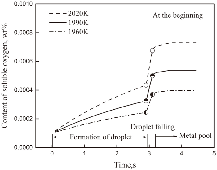
With different slag system, electric system and depth of slag pool, the temperature of slag pool will be of some difference. Figure 11 shows the effect of temperature of slag pool on the content of soluble oxygen. From Fig. 11, with the temperature of slag pool decreasing from 2020 K to 1960 K, the content of soluble oxygen at different locations all has an obvious decrease. The soluble oxygen can only precipitate during the process of cooling, which is an important source of total oxygen. Therefore, the temperature of slag pool should not be controlled too high.
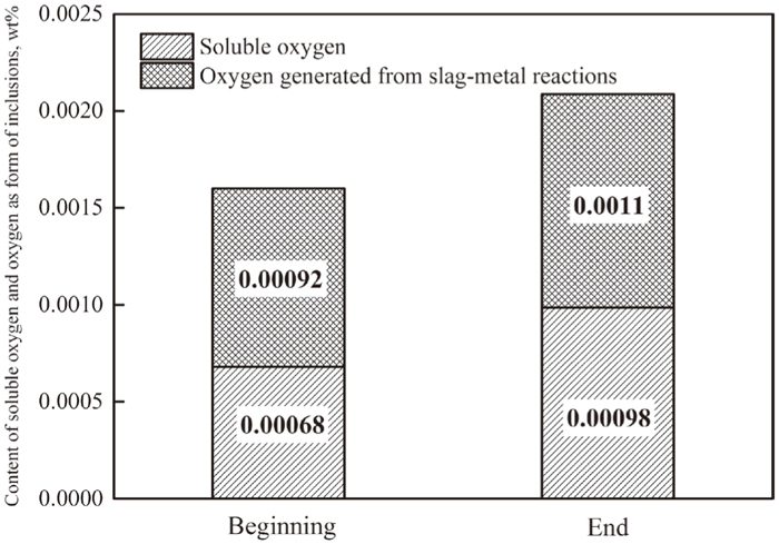
It is noted that the total oxygen consists of soluble oxygen and the oxygen as a form of inclusions at the temperature of steelmaking.
|
O
Total
=
[O]
Sol
+
O
Insol
| (39) |
Figure 12 shows the content of soluble oxygen, and oxygen as a form of inclusions which mainly results from slag-metal reactions. The type of inclusions in the ingot is mainly small single Al2O3, low-MgO MgO·Al2O3, low MgO and low CaO CaO–MgO–Al2O3 which is different from that in the electrode, indicating that ESR process has an excellent ability to purify the molten steel. From Fig. 12, it can be seen that the oxygen generated from slag-metal reactions occupies about fifty percent of the total oxygen. As mentioned above, the oxidation of Al mainly occurs at the metal film of electrode tip, and Al2O3 would generate at the slag/metal interface, most of which will be absorbed by the molten slag while some will stay in the steel. The removal rate of the inclusions is related with the surface tension between slag, steel and inclusions, the depth of metal pool, etc., which is needed to be further studied.
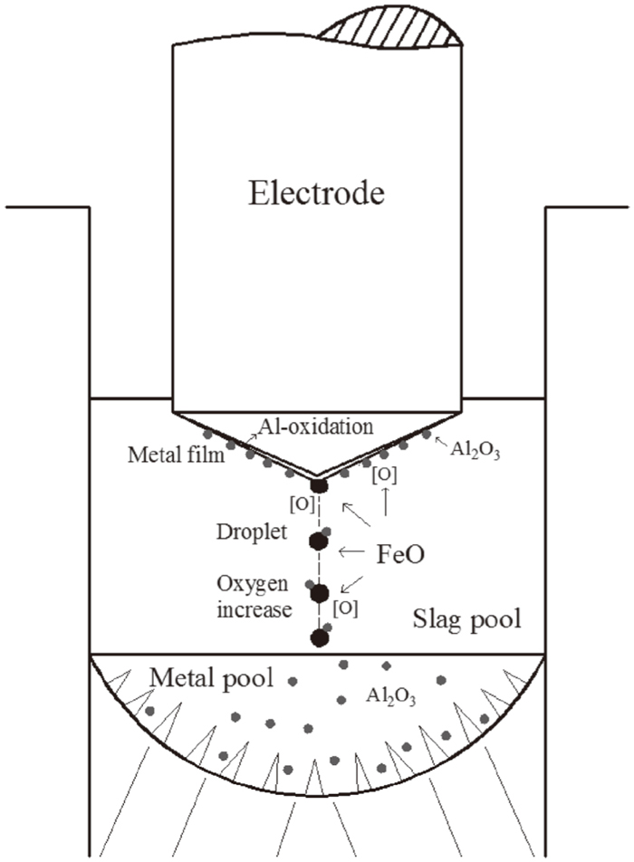
In conclusion, Fig. 13 shows the mechanism of Al-oxidation and oxygen increase during ESR process. Al in the electrode is oxidized by the iron oxide at the metal film of electrode tip, Al2O3 will generate at the interface. The result indicates quasi-thermodynamic equilibrium can be attained at this position. With the low temperature about 1815 K, the equilibrium oxygen activity at metal film is relatively low. However, during the time of droplet formation, the droplet of electrode tip is continuously heated by the molten slag to a high temperature. Thus, the content of soluble oxygen has an obvious pick-up. After the droplet detaching from the electrode tip, it is further to be heated by the molten slag, the equilibrium oxygen activity continues to increase, and the rate of FeO transfer to the slag/metal interfaces is large although the content of FeO is very low. After the droplet falling into the metal pool, the contents of Al and soluble oxygen vary little due to very low area/volume ratio. There is no doubt some of the Al2O3 generated at the metal film will be transferred to the metal pool, some of which will float upward and be absorbed by the molten slag while some will be captured by the dendrite.
In light of previous analysis, the rate-determining step of oxygen increase is controlled by the transport of FeO. On one hand, the iron oxide is the main oxidizing agent for the oxidation of Al. Therefore, a feasible method is to add strong deoxidizer Al power into the slag pool for that the products will stay in the slag pool, or strengthen the protecting atmosphere to decrease the FeO-activity to a minimum level. The value of minimum oxygen potential from thermodynamics was calculated in our previous study.7) On the other hand, mass transfer coefficient is function of slag velocity. Therefore, to reduce the flow velocity seems to be beneficial from mass transfer point of view. A practical method is to enlarge the electrode/mold ratio, since the velocity is inversely proportional to the electrode radius.
In addition, the cone angle of electrode and temperature of slag pool also play a significant role in improving the cleanliness. With a relatively flat electrode, the time of droplet formation is longer, thus the superheat of droplet becomes larger, enhancing the transfer of FeO to the slag/metal interface. An approximate cone angle of 30°–40° is necessary. In addition, with the increasing of Al content in the electrode, there is no obvious effect on the content of soluble oxygen. Therefore, it is more effective to decrease the temperature of slag pool and the time of droplet formation, rather than improve the Al content in the electrode. A feasible method is to increase the height of slag pool, or decrease the resistivity of slag to some extent.