Abstract
Pb- and Cr(VI)-free galvanized steel sheets for fuel tanks are coated with epoxy-resin films (thickness: approx. 3 µm) containing particulate Ni powder and flaky Al powder to provide a combination of weldability and degraded gasoline resistance (sour gasoline resistance). The corrosion behavior of galvanized steel specimens coated with epoxy resin containing different amounts of the two types of metal powders was investigated in a solution containing acetic acid, formic acid and NaCl at pH 3.2 and 40°C to elucidate the mechanism of corrosion protection by the coatings. The oxygen gas permeability and water vapor permeability of the coatings were also examined. The results indicated that the addition of particulate Ni powder promoted galvanic corrosion between the Ni and the Zn coating. Voids generated around the embedded Ni powder particles also appeared to accelerate the penetration of the corrosive solution through the coating. On the other hand, the addition of the flaky Al powder improved corrosion resistance. This improved corrosion resistance is associated with the suppression of direct contact between the Ni powder and the Zn coating and also with increased barrier properties, which could be confirmed from oxygen gas and water vapor permeation measurements.
1. Introduction
A Pb-Sn alloy-coated steel sheet has been used as a main material for automobile fuel tanks. Despite the satisfactory properties of the coated steel for fabrication and use in fuel tanks, the coating contains toxic Pb in the amount of 90 mass%, and the use of Pb has been restricted in the automobile industry because of tightened environmental regulations in the last decades. The Japan Automobile Manufacturers Association, Inc. proposed to reduce the amount of Pb used in the automobile industry to half or less of that in 1996 by the end of 2000 or to one-third or less by the end of 2005.1) The EU also restricted the use of Cr(VI) under Directive 2000/53/EU enacted in October 2000. Chromate treatments have been widely used for surface treatment of various practical metallic materials, including Pb-Sn alloy-coated steels, zinc-coated steels and aluminum alloys, but the amount of Cr(VI) used in a car has been restricted to 2 g or less for newly-registered cars in the EU since July 2003. In accord with the above-described environmental regulations, Pb-free and Cr(VI)-free steel materials for fuel tanks have been developed since the late 1990 s.2)
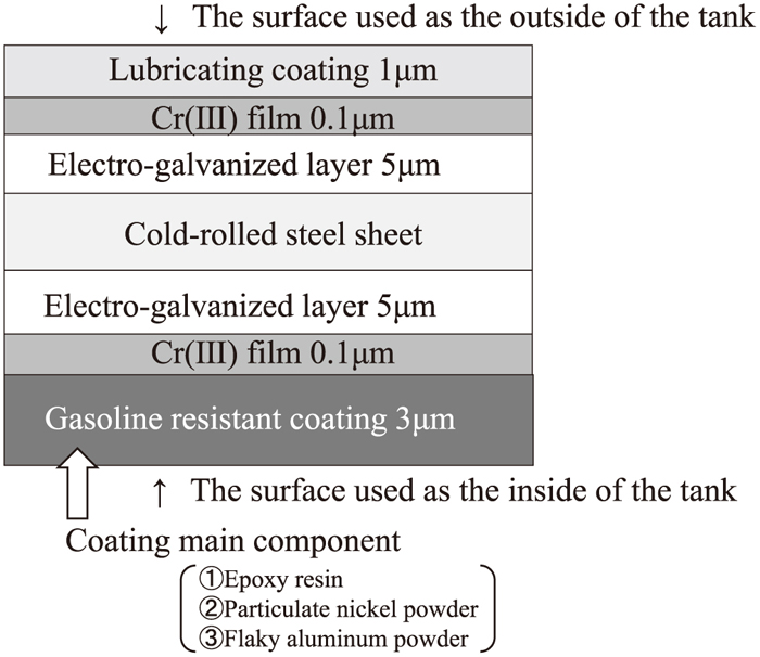
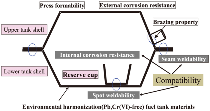
Figure 1 is an example of the Pb- and Cr(VI)-free steel for fuel tanks, which consists of electrogalvanized zinc layers and Cr(VI)-free Cr(III) oxide layers on both sides of the cold-rolled steel sheet. Furthermore, an organic layer of 1 μm thickness is coated on the outside of the tank to provide lubricating properties, while an epoxy film containing Ni and Al powders is coated on the inside of the tank to ensure sufficient welding properties and high stability in deteriorated gasoline. Figure 2 shows a schematic illustration of the shape of a typical fuel tank and summarizes the required properties of the tank material. The fuel tank consists of an upper tank shell and lower tank shell; both are formed by press forming and are then seam-welded together. A reserve cup is spot-welded to the lower tank shell. Thus, press formability, seam weldability and spot weldability are required in the tank material.
Formic acid and acetic acid are formed through the oxidation and degradation of alkenes, which are main constituents of gasoline.3) These acids are dissolved in dew condensation water, which also contains sea salt derived from the outer air environment. Thus, the tank material is exposed to a corrosive aqueous environment containing formic acid, acetic acid and chloride ions. Since the zinc coating corrodes in aqueous solutions containing these acids and chloride,4,5) organic coating of the zinc-coated steel is indispensable for corrosion protection.6) However, insulating organic coatings such as epoxy coatings show no weldability when applied in thicknesses of several micrometers.7) For this reason, metallic powders have been added to these epoxy coatings to improve weldability. It is known that weldability decreases as the particle size of iron powder becomes finer, and weldability is improved by adding metal particles larger than the coating thickness.8) The addition of Ni particles in the epoxy coating is effective for obtaining sufficient weldability, but the corrosion resistance of the zinc-coated steel decreases when the amount of Ni powder included in the epoxy coating increases. To solve this problem, an epoxy coating containing both particulate Ni powder and flaky Al powder has been developed and used practically in the automobile industry, since this coating shows sufficient weldability and corrosion resistance in the environments inside fuel tanks.2) However, the mechanism of the corrosion resistance of coatings containing both Ni and Al powders and the influence of the amounts of Ni and Al powders in the coating were not well understood.
Therefore, in this study, we examined the corrosion behavior of electrogalvanized steel with epoxy resin coatings containing various amounts of Ni and Al powders, and discussed the role of the Ni and Al powders in corrosion protection through a detailed characterization of the coatings and permeability measurements of oxygen gas and water vapor.
2. Experimental
2.1. Materials
The substrate used in this study was an electrogalvanized cold-rolled steel with a zinc layer of approximately 40 g m−2 on both sides. After alkaline degreasing with a reagent of CLN 364 S, manufactured by Nippon Parkerizing Co., Ltd., a Cr(III) layer containing 40 mg m−2 Cr(III) was formed using a coating solution containing Cr(VI) species, which completely converted to Cr(III) in the coating layer. After coating by a wire bar coating method, heat treatment was performed at 100°C. Epoxy coatings containing various amounts of Ni powder particles of 3–7 μm size and Al powder flakes with dimensions of 18 μm in the long diameter, 5 μm in the short diameter and 1 μm in thickness were prepared by a wire bar coating method at 150°C. The average coating thickness was 3 μm. In this paper, the amount of the added Ni and Al powders is expressed as parts per hundred resin (phr), i.e., the weight of the Ni or Al powder with respect to 100 parts by weight of epoxy resin. For instance, 20 phr Ni means that 20 g of Ni powder are added to 100 g of epoxy resin.
2.2. Corrosion Tests
The corrosion resistance of the coated electrogalvanized steel specimens was examined in a pH 3.2 aqueous solution containing 100 ppm formic acid, 100 ppm acetic acid and 83 ppm NaCl at 40 ±1°C. This solution was used to simulate the corrosive environment in a fuel tank.9,10) The coated specimens were cut to 30 mm × 80 mm, and the back side and edges of the specimens were masked with adhesive tape to expose only the front side of the specimens to the solution. As shown in Fig. 3, the bottom two-thirds of the specimen was immersed in the solution, and the remaining top part was exposed to a vapor phase. After immersion for various periods of time, the specimens were washed in distilled water and dried under hot air. Their corrosion resistance was evaluated by measuring the corroded area ratio with GIMP 2.8.18 software (GNU Image Manipulation Program).
2.3. SEM Observation
Prior to cross-sectional SEM observation of the specimens, a thin Pt-Pd alloy layer was coated on the specimen surface. After embedding the specimens in epoxy resin, cross-sections suitable for SEM observations were obtained by mechanical polishing. In some cases, a JEOL IB19510CP cryo-cross-section polisher was used to prepare the cross-sections in order to reduce the damage by mechanical polishing. The cross-sections thus prepared were observed by using a JEOL JSM7100F field emission gun scanning electron microscope operated at 3.0 or 5.0 kV. For elemental mapping by energy-dispersive X-ray spectroscopy (EDS), the accelerating voltage was increased to 15.0 kV.
2.4. Oxygen Gas and Water Vapor Permeation Measurements
For the oxygen gas and water vapor permeation measurements, epoxy resin coatings containing Ni and Al powders were painted on a polyimide film (Kapton 500H manufactured by Du Pont-Toray Co. Ltd.) of 125 μm thickness by a wire bar coating method. Thicker coatings of 30 μm thickness were used for the oxygen and water vapor permeation measurements to obtain a sufficiently large difference of gas permeability between the polyimide films with and without coating. An O-well Corp. Omegatrans gas permeation measurement system was used for both the oxygen gas and water vapor permeation measurements. Figure 4 shows the principle of the gas permeability measurements. The chamber was separated by a sample sheet (Fig. 4(b)) into gas introduction and permeated gas measurement sections, and the oxygen gas and water vapor that permeated through the coating were monitored by a quadrupole mass spectrometer (QMS). Water vapor permeability was measured at 40°C, 90% relative humidity and gas pressure of 6.8 kPa, and oxygen gas permeability was measured at 40°C, 90% relative humidity and an oxygen gas pressure of 100 kPa. The sample areas for both measurements were 40 mm in diameter. Prior to the gas permeation measurements, a calibration curve was obtained by the standard conductance element method proposed by Yoshida et al.11) to quantify the amount of water vapor or oxygen gas permeated through the sample sheet by the QMS. As shown in Fig. 4(a), the calibration was conducted without introducing the sample sheet.

3. Experimental Results
3.1. Corrosion Resistance
Figure 5 shows the surface appearance of the specimens after the immersion test. Corrosion resistance is obviously improved by the addition of the Al powder in the coating containing 40 phr Ni. The area surrounded by the black square was immersed in the solution. Many corroded areas (darker appearance) are present in the immersed region of specimen (A) with 40 phr Ni and no Al. Corrosion of this specimen also occurs in the vapor-exposed region above the immersed area. In both regions, the corroded area ratio clearly decreases with an increase in the amount of Al powder.

The corroded area ratio of each specimen was estimated from the image analysis of the immersed regions. Figure 6 shows the change in the average corroded area ratio of the coated steel specimens with the amount of Al powder. The corroded area ratio was only up to 8% for the coated electrogalvanized steel without Ni and Al powders, and a corroded area was not clearly detected when only Al powder was added to the epoxy coating. In contrast, addition of Ni powder greatly increased the corroded area ratio from 8% to 30–45%. No clear dependence of the corroded area ratio on the amount of Ni powder can be seen in Fig. 6, partly because of large variations of the corroded area ratio of the Ni-containing coatings. Although the addition of Ni powder was detrimental to corrosion resistance, simultaneous addition of Al powder improved corrosion resistance. Regardless of the amount of Ni powder, the corroded area ratio decreased with an increase in the amount of Al powder. The corroded area is reduced to 10% or less at 40 phr of Al when the amount of Ni powder is 20 phr, being comparable to that of the epoxy coating containing no Ni and Al powders.

Figure 7 shows SEM images of the cross-sections of corroded and non-corroded regions of the coated steel with 40 phr Ni and 10 phr Al (Sample (B) in Fig. 5). It is evident that Ni powder is located in the coating on the corroded Zn layer (Fig. 7(a)). Similarly, Ni powder was often found in the coating above corroded Zn regions. It is, therefore, likely that the accelerated corrosion by the addition of Ni is due to the formation of a galvanic couple between the Ni powder and the Zn layer. In the non-corroded region, flaky Al powder particles were often located at the bottom of the coating and prevented direct contact between the Ni powder and the Zn layer, as shown in Fig. 7(b).

Figure 8 shows the EDS images of O, Al and Ni in Fig. 7(a). Obviously, the small particle on the corroded Zn layer is Ni and the flaky material at the top of the paint layer is Al. Oxygen is present in the Zn layer, which appears at the bottom of the micrograph, confirming the corrosion of the Zn layer. The oxidation of the Al flakes and Ni powder is less significant compared with that of Zn, as seen in the EDS image of O.

In order to examine the distributions of the Ni and Al powders in the epoxy coatings further, cross-sections of the coatings containing 40 phr Ni and 10 phr Al (Sample (B) in Fig. 5) and 40 phr Ni and 40 phr Al (Sample (D) in Fig. 5) were observed before the corrosion test (Fig. 9). In sample (B) containing 40 phr Ni and 10 phr Al, the Ni powder particles were in direct contact with the Zn layer, as shown in the image of area (b) of sample (B) in Fig. 9. When the amount of Al increased to 40 phr, flaky Al powder particles were often located at the bottom of the coating and prevented direct contact between the Ni powder and the Zn layer, as shown in area (a) of sample (D). This area was also examined by EDS (Fig. 10). Apparently, an Al flake is in contact with the lower Zn layer as well as the upper Ni powder. In contrast to the images in Fig. 8, oxygen is hardly detected in the Zn layer except at the Zn layer surface. Thus, the corrosion of the Zn layer is effectively suppressed when the Al flake is located immediately above the Zn layer. The oxygen EDS image in Fig. 10 reveals only slight oxidation of the Al flake, even if the flake is in contact with a Ni powder particle. The Ni powder is also not oxidized severely in this coating. Even when the Al content in the epoxy coating was increased to 40 phr, Ni powder particles were in contact with the Zn layer, as shown in area (b) of sample (D) in Fig 9. After the corrosion test, no corrosion was found near the Ni particle covered with Al powder. We observed 34 Ni powder particles in the epoxy coating of sample (D) before the corrosion test, and 62% of the Ni powder particles were located above the flaky Al powder, as in area (a) of this sample (Fig. 9). As shown in Fig. 7(b), no corrosion occurred when the flaky Al powder was located between the Zn layer and Ni powder. The corroded area ratio of the coating with 40 phr Ni was reduced to approximately one-third by the addition of 40 phr Al (Fig. 6). The reduction of the corroded area ratio is approximately consistent with the number ratio of the Ni powder particles located on the Al powder flakes. The number of Ni powder particles covered with Al powder was only one. The very limited number of Ni particles covered by an Al powder flake suggests that this configuration of particles has little influence on overall corrosion.

The influence of the Ni and Al powders on the oxygen gas and water vapor permeability of the coatings was examined. The gas permeation rate of the polyimide films was measured with and without an epoxy coating. The gas permeation rate was reduced by the coating, such that the difference of the gas permeation rates for the polyimide films with and without the coating, i.e., the decrease in the permeation rate by the coating (ΔOPR for oxygen and ΔWPR for water), was plotted as an oxygen and water vapor permeation barrier characteristic. ΔOPR and ΔWPR are defined as follows.
|
ΔOPR=ΔOPR(
PI
)
–ΔOPR(
PI+coating
)
|
|
ΔWPR=ΔWPR(
PI
)
–ΔWPR(
PI+coating
)
|
where ΔOPR (PI) and ΔOPR (PI+coating) are the oxygen gas permeation rates of polyimide films without and with a coating, respectively. Similarly, ΔWPR (PI) and ΔWPR (PI+coating) are the respective water vapor permeation rates.
Figure 11(a) shows the change in ΔOPR with the amount of flaky Al powder. ΔOPR increases with an increase in the amount of Al. With the Al-free epoxy coatings, the oxygen permeability of the Ni-free coating is similar to that with 20 phr Ni, but a further increase in the amount of Ni results in an increase in oxygen permeability. Even with the Al-containing coatings, oxygen permeability is enhanced by the addition of Ni powder at ≥40 phr Ni. This is probably associated with the presence of voids around the Ni powders. Figure 12 shows a cross-section of the epoxy coating containing 40 phr Ni and 40 phr Al. As shown in this micrograph, voids were often found in the epoxy resin near the Ni powders, but not around Al powders. It is likely that the irregular shaped Ni powder induces the formation of these voids and thereby enhances the gas permeability. The permeability of water vapor was also examined (Fig. 11(b)). Similar to oxygen permeability, we found that water vapor permeability decreased with an increase in the amount of Al powder.

4. Discussion
4.1. Effect of Al Powder Addition on Corrosion Resistance
Compared with the coating containing no Ni or Al powder, the addition of Ni powder deteriorates corrosion resistance. The cross-sectional SEM observations of the corroded regions disclose severe corrosion of the Zn layer around the Ni powder. However, the simultaneous addition of Al powder together with Ni powder improves corrosion resistance; namely, the number of corroded regions is greatly reduced by the addition of Al. The cross-sectional SEM observations revealed that Al powder flakes were often sandwiched between the Ni powder and the Zn layer, and no corrosion of the Zn layer was found in such regions.
As shown in Fig. 7(a), severe corrosion of the Zn layer occurs around the Ni powder in the present corrosive environment, probably because of galvanic corrosion, while corrosion of the Al powder is less significant. Although Al is less noble than Ni, no severe corrosion of Al powder was found in this study even when an Al powder particle was in contact with a Ni powder particle. This suggests that Al has relatively high corrosion resistance in the present corrosive environment, and corrosion appeared not to be accelerated by contact between Al powder and Ni powder. Thus, the introduction of corrosion-resistant and less-noble flaky Al powder between the Ni powder particles and the Zn layer is effective in suppressing galvanic corrosion between Zn and Ni. It was reported that corrosion resistance increases in the following order: Zn < Zn-55% Al < Al, and a transformation from linear to parabolic kinetics was found by Zn alloying with Al.12) Mansfeld et al. measured the galvanic current of Al alloys coupled with various metals in a 3.5% NaCl solution.13) The galvanic current was rather low for the Al/Zn couple, and a higher galvanic current was found in the Al alloy/Ni couple (11–22 μA cm−2). Thus, the Ni accelerated the corrosion of Al alloys in the more corrosive solution containing a higher concentration of chloride ions, but in the present corrosive environment containing only 50 ppm chloride ions, no severe acceleration of corrosion of the Al powder was found.
When the amount of added Al powders was relatively high, the corrosion of the Zn layer was suppressed even when the Ni powder was in direct contact with the Zn layer, as shown in region (b) of sample (D) (Fig. 9). The oxygen gas and water vapor permeation measurements revealed that the barrier nature of the paint coatings was enhanced with an increase in the amount of flaky Al powder. The Al powder with dimensions of 18 μm in the long diameter and 5 μm in the short diameter effectively suppressed the penetration of the corrosive solution to the underlying Ni powder and Zn layer, probably by a labyrinth effect, contributing to prevention of corrosion. However, this configuration of the Ni and Al powders in the coating was very limited, such that the main contribution to corrosion suppression is the introduction of Al powder flakes between the Zn layer and Ni powder to prevent galvanic corrosion. The improved gas barrier property obtained by introduction of Al powder may also contribute to the improved corrosion resistance of the coated steel.
4.2. Effect of Ni Powder Addition on Corrosion Resistance
It is evident from Fig. 6 that the addition of Ni powder to an epoxy coating is detrimental to corrosion resistance. Although the corrosion resistance of Ni-containing coatings is improved by the addition of Al powder, the corroded area ratio of the Ni-containing coatings is higher than that of the Ni-free ones when the same amount of Al powder is present. There are two main reasons for the accelerated corrosion of the Ni-containing coatings. One is galvanic corrosion between the Ni powder particles and the Zn layer. As shown in Fig. 7(a), the corrosion of the Zn layer is severe near a Ni powder particle. It is known that the dissolution of Zn is accelerated by a Zn/Fe couple.14,15,16,17) Since Ni is nobler than Fe, it is likely that galvanic corrosion of Zn in contact with Ni powder occurs in this study, although it has also been reported that a Zn–Ni solid-solution alloy showed a slower corrosion rate than Zn.18)
The other reason for the increased corrosion by the addition of Ni is the increased gas permeability of the epoxy coatings. The epoxy coating contains voids near the Ni powder particles, as shown in Fig. 12. The Ni powder particles used in this study have many spike-like protrusions on their surfaces. Gas remained in the gaps between these spikes of the Ni powder in the resin solution, and then formed voids around the Ni powder after evaporation of the solvent during heat treatment. The number of voids increases with the amount of Ni powder particles, leading to increased oxygen gas and water vapor permeability through the voids (Fig. 12). The voids should also increase the permeation of the corrosive solution, reducing the corrosion protection properties of the coatings. Since such voids were not observed around the flaky Al powder, it is likely that the formation of voids is associated with the spike-like shape of the Ni powder. Thus, is it conjectured that the number of voids may increase with an increase in the number of Ni powder particles, resulting in the increased permeability observed in this study.
5. Conclusions
Epoxy coatings containing various amounts of particulate Ni powder and flaky Al powder were applied to electrogalvanized steel, and their corrosion behavior was examined by immersing specimens in an aqueous solution containing 100 ppm formic acid, 100 ppm acetic acid and 83 ppm NaCl at 40°C for 350 h. From the distribution analysis of the Ni and Al powders in the coatings, gas permeation measurements of the coatings and characterization of the corroded samples, the following conclusions were drawn.
(1) The addition of Al powder improves the corrosion resistance of the coatings containing any amount of Ni powder (0, 20, 40 and 70 phr Ni).
(2) Severe corrosion of the Zn layer occurs near a Ni powder particle because of galvanic corrosion. However, flaky Al powder is often located near the Zn/coating interface, preventing direct contact between the Ni powder and the Zn layer, particularly when the added amount of Al is high (≥40 phr Al), and this results in improved corrosion resistance.
(3) Although the Ni powder increases gas permeability by introducing voids in the coating, the flaky Al powder greatly reduces both oxygen and water vapor permeability by the labyrinth effect. This reduction of permeability probably also contributes to improved corrosion resistance.
References
- 1) Recycling Target for End-of-life Vehicles,METI, Industrial Structure Council and Automobile Disposal and Recycling Subcommittee, Ministry of Economy, Trade and Industry, Tokyo, (1996).
- 2) S. Suzuki, H. Ogata, S. Umino and C. Kato: Tetsu-to-Hagané, 89 (2003), 1.
- 3) M. Nakamura and Y. Yamamoto: Technical Paper of Society of Automotive Engineers of Japan, Vol. 956, Society of Automotive Engineers of Japan, Tokyo, (1995), 221.
- 4) T. Mizuguchi, R. Abe and Y. Makoto: Curr. Adv. Mater. Process., 6 (1993), 1539.
- 5) M. Fuda, T. Izaki and T. Omori: Curr. Adv. Mater. Process., 10 (1997), 1237.
- 6) M. Sagiyama and N. Morito: Tetsu-to-Hagané, 81 (1994), 401.
- 7) T. Watanabe, Y. Shindou, T. Shiota, K. Yamato and S. Nomura: Proc. Int. Conf. on Zinc and Zinc Alloy Coated Steel Sheet (Galvatech ’89), ISIJ, Tokyo, (1989), 80.
- 8) J. Oka and H. Iwakura: Tetsu-to-Hagané, 73 (1987), 2235.
- 9) H. Ogata, S. Suzuki and K. Mochizuki: Kawasaki Steel Giho, 32 (2000), 21.
- 10) H. Ogata, S. Suzuki, S. Umino and K. Mochizuki: SAE Technical Paper, Paper No. 2000-01-0307, SAE International, Warrendale, PA, (2000).
- 11) H. Yoshida, K. Arai, M. Hirata and H. Akimichi: Vacuum, 86 (2012), 838.
- 12) A. R. Marder: Prog. Mater. Sci., 45 (2000), 191.
- 13) F. Mansfeld, D. H. Hengsten and J. V. Kenkel: Corrosion, 30 (1974), 343.
- 14) X. J. Raj and T. Nishimura: J. Mater. Eng. Perform., 25 (2016), 474.
- 15) D. L. Zhang, W. Wang and Y. Li: Corros. Sci., 52 (2010), 1277.
- 16) R. M. Souto, Y. Gonzalez-Garcia, A. C. Bastos and A. M. Simoes: Corros. Sci., 49 (2007), 4568.
- 17) A. M. Simoes, A. C. Bastos, M. G. Ferreira, Y. Gonzalez-Garcia, S. Gonzalez and R. M. Souto: Corros. Sci., 49 (2007), 726.
- 18) J. B. Bajat and V. B. Miskovic-Stankovic: Prog. Org. Coat., 49 (2004), 183.


