Regular Article
Slag/Metal Separation from H2-Reduced High Phosphorus Oolitic Hematite
2017 Volume 57 Issue 12 Pages 2131-2140

Details
2017 Volume 57 Issue 12 Pages 2131-2140
A process of H2 reduction followed by the slag/metal separation for the utilization of high-phosphorus oolitic hematite has been proposed. The H2 reduction was conducted at 1073 K in a horizontal rotary electric resistance furnace, which significantly promotes the metallization ratio of reduced ore fines. Thermodynamic calculation of H2 reduction for apatite and XRD analysis of ore samples before and after H2 reduction confirmed that gangue minerals containing P, Al and Si in oolitic hematite hardly be reduced. The slag/metal separation was carried out in an induction furnace at 1873 K. After separation, metal block and slag were obtained, and most of gangue minerals combined with lime and calcium fluoride formed the slag, but some impurities remained in the form of slag inclusions in the metal. Based on the SEM-EDS examination of P-containing slag inclusions and ternary phase diagram of Fe–P–O system computed by FactSageTM 6.4 at 1873 K, phosphorus in the metal product can be precipitated as iron phosphate or iron phosphide, and the evolution of P-containing slag inclusions is Fe2P(l) + Fe3(PO4)2(l)→Fe3(PO4)2(l)→FeO(l) along with the increase of slag basicity, melt separation time and additive CaF2. A satisfactory metal product with 99.80 wt% T. Fe, 0.027 wt% P, 0.0013 wt% Si, 0.004 wt% Al and 0.05 wt% O was achieved by the slag/metal separation under the optimum conditions: slag basicity of 2, melt separation time of 10 min, CaF2 mixing ratio of 4 wt% and metallization ratio of reduced fines of 85.9%.
Oolitic hematite ore, characterized by complex mineral phases, unique concentric oolitic texture and high phosphorus content, is considered to be one of the most refractory iron ore resources. It is widely distributed in France, Canada, Saudi Arabia and China.1) There are approximately 22 billion tons of high-phosphorus iron ores with an average of 1.0 wt% phosphorus in China,2) which cannot be supplied on a large scale for the blast furnace as ironmaking raw material. Therefore, it is of great urgency to make full use of the refractory ores. Until now, many technical routes have been proposed for the utilization of high-phosphorus iron ores, including physical separation,3,4) bio-leaching,5,6) flotation7,8) and hydrometallurgical process.9)
The reduction process, one of the typical processes for the treatment of oolitic hematite ore, including direct10,11) and indirect reduction,12,13) has received considerable attention in recent years. The route of direct reduction, mostly used carbon as the reductant and followed by the magnetic separation, was recommended to be a feasible way for the iron recovery and simultaneous dephosphorization from oolitic hematite ore. During the carbon-based reduction, the apatite will be reduced to P2 or PO vapors to be removed at the temperature of 1471 K or 1771 K, respectively.14) Moreover, sodium salts were added in the reduction process, such as Na2CO3 and Na2SO4, which were beneficial for enhancing the dephosphorization and the reduction of iron oxide.15) However, the phosphorus content of the obtained magnetic concentrate was still high, owing to the inevitable migration of phosphorus into the metallic iron by the reduction of apatite during the carbon-based reduction. So, the process of indirect reduction followed by the melt separation has been conducted to prepare metallic iron from oolitic hematite ore.16) The process in which iron oxide was reduced by H2, CO or their mixture under a relatively low temperature,17) can effectively avoid the reduction of P-containing gangue under the premise of high reduction degree of iron ore. Furthermore, the dephosphorization for high-phosphorus oolitic hematite ore can be significantly enhanced by melt separation with the aid of additives CaO and NaCO3, and the P content in the metal product can meet the requirements for ironmaking raw materials.
Previous studies on gas-based reduction combined with melt separation for treating high-phosphorus oolitic hematite ore were explored by the electric resistance furnace for the melt separation focusing mainly on the high dephosphorization with relatively low iron loss. But the variation of composition and morphology of slag inclusions remained in iron phase after the melt separation was less investigated. Also, the change of other elements such as Al and Si in the metal product under different melt conditions was not fully investigated. Moreover, induction furnaces have a large potential of improving the efficiency of the slag/metal separation due to the stirring effect of electromagnetic field. However, the melt separation by using the induction furnaces was rarely stated.
In this study, the slag/metal separation process for treating high-phosphorus oolitic hematite ore was presented mainly for dephosphorization and recovery of iron from this ore. For dephosphorization, it requires not only higher oxygen potential and basicity of slag, but also relatively lower temperature. For recovery of iron, the proper melting temperature and time are necessary conditions for the separation of iron and slag. Meanwhile, the addition of CaF2, an effective fluxing agent, can significantly increase the fluidity of slag, which is also favorable for the removal of phosphorus and separation of iron and slag. Hence, the effect of the temperature and time of melt separation, basicity of slag, addition of CaF2 and the metallization ratio of reduced fines were investigated to evaluate the feasibility of the process of H2 reduction followed by the slag/metal separation for oolitic hematite ore. Besides, the change of Al and Si, and the evolution of microstructure and composition of slag inclusions remained in the metal product obtained from different melt conditions were also discussed.
The lumpy oolitic hematite ore from Hubei province in China was used in this research and the lump ore was crushed and ground to 96–120 μm in particle size. Table 1 shows the chemical composition of this ore. The content of P is 0.65 wt%, which makes it unsuitable for the traditional ironmaking process by blast furnaces, and the contents of SiO2 and Al2O3 are relatively high of 8.96 and 4.92 wt%, respectively, which also brings a large burden for blast furnace operation.
| T. Fe | P | Al2O3 | SiO2 | S | MgO | CaO |
|---|---|---|---|---|---|---|
| 56.27 | 0.65 | 4.92 | 8.96 | 0.02 | 0.68 | 2.3 |
H2 used as the reductant during the reduction process and Ar used as the inert gas during the reduction and melt separation process are both in high purify of 99.999 vol%. The additives of CaO and CaF2, used in the slag/metal separation are of analytical regent (AR) grade.
2.2. Methods 2.2.1. H2 ReductionAbout 200 g ground iron ore sample in a quartz reactor (with the inner diameter of 54 mm and the length of 1250 mm), was put into the fixed high temperature zone of a horizontal rotary electric resistance furnace. Ar was introduced into the reactor to replace the air at room temperature for several minutes. Afterwards, the ore fines were isothermally reduced in the furnace by H2 at a flow rate of 1 L/min with a rotating speed of 10 rpm at 1073 K which was measured by the two K-type thermocouples near the side wall of quartz tube (see Fig. 1). After the H2 reduction for predetermined time, H2 was switched to Ar, and the reduced fines were cooled down in the furnace to the ambient temperature.

Schematic of the H2 reduction process (1. K-type thermocouple; 2. Pressure valve; 3. Quartz tube; 4. Insulation material; 5. Heating wire; 6. Porous quartz plug).
Batches of 11–12 g of reduced ore fines mixed with an amount of powder additives (CaO, CaF2) were put into the high-alumina crucibles (with the inner diameter of 23 mm and the height of 72 mm), then placed the crucibles into an induction furnace at the predetermined temperature under the protective gas of argon with a flow rate of 30 mL/min for the melt separation. After holding for the fixed time, the furnace was cooled to room temperature and the sample was taken out subsequently.
The mixing ratio of CaF2 is the mass ratio between the added CaF2 and reduced fines. The amount of added CaO is determined according to the slag basicity (R), which is defined as Eq. (1):
| (1) |
The metallization ratio of reduced fines after H2 reduction (MR), the iron recovery (ε) and element removal ratio (ηi) after the slag/metal separation are shown in Eqs. (2), (3), (4).
| (2) |
| (3) |
| (4) |
The phase composition in the oolitic hematite ore, reduced fines and slag part were determined by the XRD analysis with Cu Kα radiation. The analysis of reduced fines, metal product and slag part were performed by wet chemical method and ICP-AES. The iron oxides in slag consist of mainly FeO and a few Fe2O3, and we assumed all iron in ferrous and ferric oxides as FeO. Subsequently, the microstructure and chemical composition of slag inclusions in the metal product were also examined by SEM and EDS.
Figure 2 illustrates changes of the total iron (TFe), total metallic iron (MFe) and metallization ratio of reduced fines (MR) with H2-reduced time at 1073 K. With reduction time increasing, TFe changed little but MFe and MR increased obviously. When reduction time reached 5 h, MFe and MR rose up to 63.2 wt% and 87.1%, respectively. In contrast, Tang et al.13) has reported that after 5 h reduction by high purity of H2 gas at 1073 K in the vertical static tube furnace, the iron metallization ratio of 80 g oolitic hematic powder was still less than 70%. The obvious difference in MR attributed to the two different kinetic factors from this work. One is that the raw ore before supplied to the furnace in this experiment was more finely ground than that of work by Tang et al, which ensure sufficient contact of ore fines with reducing gas in the reduction process. The other is that the kinetic conditions provided by the horizontal rotary electric resistance furnace were better than that of the vertical static electric resistance furnace, which could greatly promote the mass transfer and guarantee the homogeneity of fines distribution in the reactor.

TFe, MFe and MR of reduced fines with different H2-reduced time at 1073 K.
As for the behavior of phosphorus during H2 reduction, phosphorus is mainly in the form of apatite with chemical formula Ca5(PO4)3(F, OH).18) On account of high contents of SiO2 and Al2O3 in the oolitic hematite ore, the thermodynamic calculations for reactions between H2 and apatite should consider the presence of SiO2 and Al2O3. The possible reactions are listed as follows (Eqs. (5), (6), (7), (8), (9), (10), (11)) and the thermodynamic calculations of each reaction in standard state were estimated by HSC chemistry® 5.1 (see Fig. 3). The results show that the phosphorus in fluorapatite (Ca5(PO4)3F) can be reduced to P2, P4, PO or PO2 by H2 as temperature rises to 4153 K (Eq. (5)), 4973 K (Eq. (6)), 3363 K (Eq. (7)) or 3453 K (Eq. (8)), respectively. For the reactions between H2 and hydroxyapatite (Ca5(PO4)3OH), the P2, PO or PO2 can be formed in the temperature of 4473 K (Eq. (9)), 3243 K (Eq. (10)) or 3343 K (Eq. (11)), respectively. The P2, P4, PO or PO2 vapors can be easily incorporated into metallic iron,19) which will cause the high P content in reduced fines and make it difficult for the dephosphorization on the subsequent slag/metal separation. However, the reactions (5)–(11) can hardly occur as the H2 reduction temperature of 1073 K is far below the critical temperature of these reactions. In combination with the XRD patterns of ore samples before and after H2 reduction, as shown in Fig. 4, after H2 reduction at 1073 K for 5 h, only hematite was reduced to wustite and iron, whereas other phases including apatite and quartz remained stable in reduced fines, which reveals that the gangue minerals containing P, Al and Si in oolitic hematite ore were not reduced. Hence, it provides the possibility for the removal of gangue minerals in the following slag/metal separation.
| (5) |
| (6) |
| (7) |
| (8) |
| (9) |
| (10) |
| (11) |

Thermodynamic computation results for reactions between H2 and apatite with the existence of SiO2 and Al2O3.

XRD patterns of ore samples before and after H2 reduction.
The schematic of slag/metal separation is illustrated in Fig. 5 showing that owing to the lower density of the molten slag than that of hot metal at high temperature, the metal droplets are continuously sank, then separated from the slag phase, and finally aggregated and grown into a block of metal. Due to the effects of surface tension of hot metal at high temperature and the gravity, the shape of the final metal product likes an ellipsoid. The macro images of the metal product and slag part obtained at three different temperatures indicate that the temperature is dominant factor determining the slag/metal separation behavior. At 1673 K, reduced fines are partially molten resulting in the mixed phase consisting of un-melted slag and iron. At 1773 K, the shape of the metal product approximates cake shape, with some metal particles in the slag part nevertheless. It indicates that increasing temperature accelerates the sinking of metal droplets and benefits for the floating of slag phase. At 1873 K, reduced fines could be fully melted to form the final metal product and slag. Therefore, the metal particles could hardly find in the slag part. Considering the energy consumption, 1873 K is the appropriate melt separation temperature although increasing temperature can improve the slag/metal separation. Meanwhile, the melt separation time of 8 min is the minimum time to achieve a complete separation of metal and slag at 1873 K, so the melt separation temperature is fixed to 1873 K and the melt separation time is at least 8 min in the subsequent experiments.

Schematic of the slag/metal separation process.
The effect of slag basicity (R) on the slag/metal separation at 1873 K, under the conditions of melt separation time of 11 min and metallization ratio of reduced fines (MR) of 80.0%, is shown in Fig. 6.

Effect of slag basicity on the slag/metal separation at 1873 K: (a) P, Al and Si content in the metal product (b) ηi (i=P, Al or Si) and ε after slag/metal separation.
Figure 6(a) illustrates that with the slag basicity (R) increased from 1 to 3, the P content in the metal product sharply decreased, meanwhile, the Al and Si content also decreased. Correspondingly, from Fig. 6(b), the dephosphorization (ηP) rose significantly while the dealumination (ηAl) and desiliconization (ηSi) are both higher than 99%. As for iron recovery (ε), it increased from 75.3 to 78.3% as basicity increased from 1 to 2, but slightly decreased by adding much CaO to be 3 in basicity. The above results show that increasing basicity enhances the removal of P, Al and Si, however, excessive basicity would change the melting temperature and the viscosity of slag, which retards the slag/metal separation and leads to a lower ε.
Furthermore, the composition and phases of slag part obtained under different basicity on the slag/metal separation were examined to distinguish the sharp difference of the removal of P, Al and Si. The main compositions of slag were CaO, FeO, SiO2 and Al2O3, in which the total mass of CaO, FeO and SiO2 was accounted for 90%. Hence, the composition of slag are plotted in the calculated pseudo-ternary phase diagram of CaO–FeO–SiO2 containing 10 wt% Al2O3 (see Fig. 7), in which the computed liquids lines at different temperatures from 1000°C to 1600°C by the FactSageTM 6.4 were shown. Figure 7 shows that as the basicity increased from 1 to 3, the melting temperature of each slag under R=1, 1.5, 2 or 3 estimated from the diagram was 1175, 1257, 1274 and 1394°C, respectively, which gradually moved toward the high temperature areas but still located in the liquid region of 1100°C to 1400°C. It indicates that the unreduced FeO and gangue mineral phases of Al2O3 and SiO2 in reduced fines can react with CaO to form CaO–SiO2–FeO–Al2O3 slag with relatively low melting temperature. In combination with the XRD patterns of slag with different basicity in Fig. 8, with R=1, Fe2SiO4, FeO and Ca2Al2SiO7 were observed in the slag system, suggesting that the Al and Si bearing gangue in the metal product were removed into slag in the form of Fe2SiO4 and Ca2Al2SiO7 when slag solidified. With R=2, the characteristic peaks of Ca2Al2SiO7 became stronger, and the Ca2SiO4 was also found, which indicates that the increase of CaO promoted the ηAl and ηSi. With much CaO into reduced fines for R=3, lots of strong peaks of Ca2SiO4 with high melting point of 2130°C appeared, which could cause the increase of melting temperature and viscosity of slag. However, from the XRD analysis, the Fe2SiO4 with low melting point of 1205°C and FeO which is beneficial for the fluidity of slag, always exist in the slag system. Additionally, Cao et al.20) reported that the olivine [(Fe, Ca)2SiO4)] and melilite (Ca2Al2SiO7) could interact and result in the generation of eutectics which could lead to the melting of minerals. Thus, the slag with low melting temperature could melt earlier than the iron phase, and has excellent fluidity,21) which is favorable for its removal by floating and slag/metal separation, thus resulting in the high ηSi and ηAl.

Liquids lines from 1000°C to 1600°C in CaO–FeO–SiO2 pseudo-ternary phase diagram with 10 wt% Al2O3.

XRD patterns of slag with different basicity.
However, the phosphorus removal differs from that of silicon and aluminum, owing to its unique distribution characters in reduced fines and the removal mechanism. Phosphorus distributed in reduced fines is still in the form of apatite, and the apatite layer is thin to less than 50 μm in size and sandwiched between the iron minerals tightly, which makes it easy to react with iron and difficult to separate from iron phase.11) Furthermore, the removal mechanism of phosphorus requires not only higher oxygen potential,22,23) but also higher slag basicity24) to lower phosphorus oxide (P2O5) activity and prevent the rephosphorization, due to the poorer stability of phosphorus oxide than that of silicon and aluminum oxide at high temperature. Therefore, the proper basicity of 2 was set in the subsequent experiments, where high dephosphorization and iron recovery could be attained simultaneously.
3.3.2. Effect of Melt Separation TimeFigure 9 shows the effect of melt separation time on the slag/metal separation at 1873 K with 2 for R and 80.0% for MR.

Effect of melt separation time on the slag/metal separation at 1873 K: (a) P, Al and Si content in the metal product (b) ηi (i=P, Al or Si) and ε after slag/metal separation.
It is evident in Fig. 9(a) that the content of P, Al and Si in the metal product decreased with the increase of melt separation time, and the decline of P content was more obvious than that of Al and Si. Meanwhile, the ηAl and ηSi slightly increased while the ηP significantly increased (Fig. 9(b)). When time reached 10 min, the content of P, Al and Si in the metal product decreased to 0.05, 0.006 and 0.0015 wt% respectively, and the ηP, ηAl and ηSi rose to 96.88, 99.92 and 99.98%, correspondingly. However, the ε decreased continuously from 80.0 to 77.5% with the extension of melt separation time. It indicates that as time increased, the slag inclusions can comparatively float up sufficiently and the hot metal got more purified, thus the P, Al and Si content in the metal product decreased. The floating of slag inclusions will inevitably take away some iron, and the more purified hot metal means the more sacrifice of iron, which leads to the decline of ε. Therefore, the melt separation time of 10 min is recommended.
3.3.3. Effect of CaF2According to the previous separation results under the different melt separation time and slag basicity, CaO plays a significant role in the ηP, ηAl and ηSi during the slag/metal separation. However, with basicity increased, the melting temperature of slag moves further away from the liquid region of 1100°C to 1400°C, which demonstrates that the addition of CaO will necessarily increase the melting temperature and viscosity of slag, resulting in lower separation efficiency of metal from slag (as shown in Fig. 7). CaF2, an effective fluxing agent, can significantly increase the fluidity and decrease the melting temperature, but cannot decrease the basicity of slag simultaneously.25) Therefore, the effect of CaF2 on the slag/metal separation at 1873 K was studied under the conditions of R=2, melt separation time of 10 min and MR= 80.0%. The results are shown in Fig. 10.

Effect of CaF2 on the slag/metal separation at 1873 K: (a) P, Al and Si content in the metal product (b) ηi (i=P, Al or Si) and ε after slag/metal separation.
As can be seen in Fig. 10(a), it is clear that with the CaF2 ranging from 0 to 8 wt%, the content of P, Al and Si in the metal product decreased from 0.05 to 0.01 wt%, 0.006 to 0.003 wt% and 0.0015 to 0.0010 wt%, respectively. Meanwhile, from Fig. 10 (b), the ηP, ηAl and ηSi increased from 96.88 to 99.10%, 99.92 to 99.96% and 99.98 to 99.99%, correspondingly. When the CaF2 mixing ratio was added from 0 to 8 wt%, the ε fluctuated within 78.3 to 78.6% after the slag/metal separation. Even though the additive CaF2 can promote the removal of P, Al, and Si in the metal product, Cho et al.26) reported that the addition of small amounts of CaF2 will result in significant increase of the rate of alumina dissolving into slag, which means that the CaF2 has a strong effect of corrosion on alumina crucible used in this experiment. Hence, considering the two aspects comprehensively, the 4 wt% addition of CaF2 is the preferable mixing ratio.
3.3.4. Effect of Metallization Ratio of Reduced FinesOn basis of the results of previous slag/metal separation under the optimum conditions, the P, Al and Si content in the metal product could decrease to 0.019, 0.004 and 0.0013 wt% respectively, whereas the ε was less than 80.0%. It is mainly attributed to the lower metallization ratio of reduced fines. Hence, reduced fines obtained from 1 to 5 h H2 reduction were selected to study the effect of MR on the slag/metal separation at 1873 K under the conditions of R=2, melt separation time of 10 min and 4 wt% CaF2 addition, as shown in Fig. 11.

Effect of MR on the slag/metal separation at 1873 K: (a) P, Al and Si content in the metal product (b) ηi (i=P, Al and Si) and ε after slag/metal separation.
Figure 11(a) illustrates that, as the MR increased from 72.5 to 87.1%, the P content in the metal product increased significantly while the Al and Si content changed little. Correspondingly, the ηP decreased obviously while there are no marked changes of ηAl and ηSi. As for iron recovery (ε), it rose greatly (see Fig. 11(b)). The above results demonstrate that the higher the MR, the more the metallic iron and the less the FeO content in reduced fines, thus the ε got significantly improved. However, the oxygen potential and fluidity of slag will be decreased due to the decline of FeO content in reduced fines,12) which leads to the increase of P content in the metal product. Meanwhile, owing to the lower concentration gradient of Al and Si under the previous optimum conditions, no significant changes of Al and Si content were detected. In order to maximize ε from reduced fines while minimize the P, Al and Si content in the metal product, 85.9% (4 h H2 reduction) was set as the appropriate MR.
Based on the above results, a satisfactory product was obtained from the slag/metal separation at 1873 K under the conditions: R=2, melt separation time of 10 min, 4 wt% CaF2 addition and MR=85.9%. The chemical composition of the satisfactory metal product is shown in Table 2. If using reduced fines with lower metallization ratio, higher dephosphrouzation can be obtained.
| T. Fe | P | Si | Al | S | Mn | O |
|---|---|---|---|---|---|---|
| 99.80 | 0.027 | 0.0013 | 0.004 | 0.009 | 0.0011 | 0.05 |
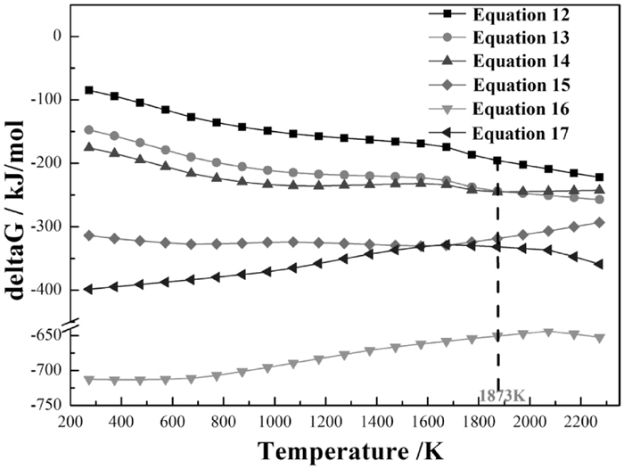
Based on the SEM and EDS examination of slag inclusions in the metal product obtained under different melt conditions, a large number of Fe–P–O slag inclusions were found. In order to clarify the evolution of P-containing slag inclusions under different melt conditions, the possible reactions (Eqs. (12), (13), (14), (15), (16), (17)) with the thermodynamic calculations under standard state from HSC chemistry® 5.1 and SEM-EDS analysis of typical P-containing slag inclusions were presented in Figs. 12 and 13, respectively.
| (12) |
| (13) |
| (14) |
| (15) |
| (16) |
| (17) |
Thermodynamic computation of possible reactions.

SEM images and EDS analysis of slag inclusions in the metal product obtained at 1873 K under different melt conditions: (a) R=1; Melt separation time of 8 min. (b) R=2; Melt separation time of 10 min. (c) R=2; Melt separation time of 10 min; 4 wt% mixing ratio of CaF2.
From Fig. 12, P2O5 can easily react with Fe, FeO or CaO to form the P-containing phases of FexP (x=1, 2, 3) (see Eqs. (12), (13) and (14)), Fe3(PO4)2 (Eq. (15)) or Ca3(PO4)2 (Eq. (16)), respectively, as the values of Gibbs free energy change of each reaction in the temperature range from 273 K to 2273 K are far less than 0. Meanwhile, based on the values of Gibbs free energy change of reactions (12)–(16) at 1873 K, the stability of the P-containing phases from strong to weak is in the order of Ca3(PO4)2 > Fe3(PO4)2 > FexP (x=1, 2, 3), and as for the FexP (x=1, 2, 3), it is clear that the Fe2P and Fe3P are more stable than the FeP.
Figure 13(a) depicts that a typical Fe–P–O slag inclusions were precipitated and scattered in the metal product which obtained from the melt separation at 1873 K under the conditions of R=1 and melt separation time of 8 min, and the EDS analysis of the point 1 shows that the mass ratio of Fe, P and O in this inclusions is 46.8, 17.6 and 35.6 wt%, respectively, which is completely consistent with that of Fe3(PO4)2 and indicates the reaction (15) occurred. Moreover, some dissolved phosphorus was observed in the iron matrix with the mass fraction of 1.5 wt% (see the EDS analysis of point 2). The result reflects that P may exist in the form of iron phosphide, such as FexP (x=1, 2, 3) in the metal product,12) which means the reactions (12)–(14) also occurred. When the basicity and melt separation time increased up to 2 and 10 min, respectively, it is evident in Fig. 13(b) that P-containing slag inclusions mainly exist in the form of compound slag inclusions, which distinctly exhibit two areas with different colors. According to the EDS analysis of each area, the dark-colored area represents the Fe–P–O phase and the mass ratio among Fe, P and O was 62.9, 11.3, and 25.8 wt%, respectively, where the mass fractions of P and O are lower than that of Fe3(PO4)2. The light-colors area is the Fe–O phase, and the mass ratio between Fe and O is close to that of FeO. In addition, almost no dissolved phosphorus but Fe phase is observed in the iron matrix. It indicates that with the increase of basicity and melt separation time, the reactions (12)–(15) are hardly to happen, which causes the rare existence of FexP (x=1, 2, 3) and Fe3(PO4)2 phases in the metal product. Meanwhile, P2O5 from reduced fines are inclined to react with CaO and formed the stable calcium phosphate (Ca3(PO4)2) owing to the strong affinity between acid oxide of P2O5 and basic oxide of CaO, which means only when CaO reaches a certain amount in the molten slag, P2O5 can be removed effectively and avoided to migrate into iron phase in large amount due to the occurrence of reaction (16). Even though there are some Fe3(PO4)2 generated according to reaction (15), it will be converted into Ca3(PO4)2 and FeO by the reaction (17), due to the stronger alkalinity of CaO than that of FeO. But the conversion of Fe3(PO4)2 was not fully completed under such melt conditions, which attributes to the formation of compound slag inclusions in Fig. 13(b). With the addition of 4 wt% CaF2, it is clear in Fig. 13(c) that the dark-colored area of compound slag inclusions becomes smaller than that of in Fig. 13(b) and the relative intensity of characteristic peaks for P and O in the dark-colored area decreases significantly. It demonstrates that with the addition of CaF2 as flux, the phosphorus content in the P-containing slag inclusions further decreases and compound P-containing slag inclusions gradually become the single FeO slag inclusions according to the EDS analysis in Fig. 13(c). However, the slag inclusions like Ca3(PO4)2 have not been observed though the reaction (16) is easy to happen in this work, and such observation was also revealed by Guo.12) It may attributed to the stronger stability of Ca3(PO4)2 than that of Fe3(PO4)2 and FexP (x=1, 2, 3) and its limited solubility into iron phase, which contributes to the effective removal of Ca3(PO4)2 into slag phase by floating during the melt separation.
To verify the evolution mechanism of P-containing slag inclusions further, composition of this slag inclusions observed in each melt condition is plotted in the ternary phase diagram of the Fe–P–O system, which was computed by the FactSageTM 6.4 at 1873 K (see Fig. 14). Meanwhile, the melting points of corresponding compounds were also shown in Table 3.

Evolution of P-containing slag inclusions observed under different melt conditions in the Fe–P–O phase diagram computed by the FactSageTM 6.4 at 1873 K: (a) R=1, 2 and 3; melt separation time of 11 min (b) R=2, melt separation time of 8, 9 and 10 min (c) R=2, melt separation time of 10 min, additive CaF2 of 2, 4 and 6 wt%.
| FeO | Fe2O3 | Fe3P | Fe2P | FeP | Fe3(PO4)2 |
|---|---|---|---|---|---|
| 1650 | 1838 | 1438 | 1643 | 1735 | 1293 |
As can be seen from Table 3, the melting points of P-containing slag inclusions are all lower than 1873 K. It indicates that the P-containing slag inclusions exist in liquid phases at 1873 K, which is favorable for their removal to slag. Meanwhile, from the variation tendency of P-containing slag inclusions in Fig. 14(a), with the slag basicity increases from 1 to 3, the evolution of P-containing slag inclusions is concluded to be: Fe2P (l) + Fe3(PO4)2 (l)→Fe3(PO4)2 (l)→FeO (l). Both Fe3(PO4)2 and Fe2P were found at R=1 in the phase diagram, which reveals that P could be precipitated as iron phosphides and iron phosphates at R<2. Owing to the stronger stability of Fe2P and Fe3P than that of FeP (see Fig. 12) and relatively high phosphorus content of 0.65 wt% at R=1 in the metal product (see Fig. 6), the iron phosphide is more likely to be Fe2P rather than FeP and Fe3P in the phase diagram. Furthermore, Figs. 14(b) and 14(c), show that the liquid phase of Fe3(PO4)2 is the main phase in P-containing slag inclusions as the melt separation time ranges from 8 min to 10 min. With the CaF2 additive varying from 2 to 6 wt%, the liquid phase of Fe3(PO4)2 become less and less, and the FeO appears to be the dominated phase in slag inclusions. From the above results in Fig. 14, the evolution of P-containing slag inclusions are in good agreement with the SEM-EDS examination in Fig. 13, and the effect of basicity on dephosphorization is greater than that of the melt separation time and addition of CaF2 owing to the significant decline of P and O content in P-containing slag inclusions. Hence, the phosphorus content of slag inclusions in metal product can be decreased effectively by gradually optimizing slag basicity, melt separation time and the addition of CaF2 on the slag/metal separation.
Thermodynamic calculation for H2 reduction of fluorapatite and hydroxyapatite and XRD analysis for ore samples before and after H2 reduction indicated that gangue minerals containing P, Al and Si in oolitic hematite ore cannot be reduced and dissolved into metallic iron, which provides the possibility for the removal of gangue minerals by the slag/metal separation.
By adding lime and small amount of CaF2 as fluxes for the separation of metal and slag in the induction furnace, the gangue minerals containing P, Al and Si could be effectively removed from the H2-reduced high phosphorus oolitic hematite, resulting in the formation of pure iron without carbon.
The proper temperature for achieving a good slag/metal separation was 1873 K. At 1873 K, the P, Al and Si content in the metal product could be decreased to 0.027, 0.004 and 0.0013 wt%, respectively, and the iron recovery reached as high as 86.3% under the conditions: slag basicity of 2, melt separation time of 10 min, 4 wt% CaF2 and the metallization ratio of reduced fines of 85.9%. The metal product with lower P content of 0.019 wt% can be obtained if the metallization ratio of reduced fines is 80.0%.
SEM-EDS examination of P-containing slag inclusions and computed Fe–P–O phase diagram revealed that phosphorus in the metal product could be precipitated as iron phosphate (Fe3(PO4)2) or iron phosphide (Fe2P), and the sequence of the evolution of P-containing slag inclusions was Fe2P(l) + Fe3(PO4)2(l)→Fe3(PO4)2(l)→FeO(l) along with the increase of slag basicity, melt separation time and additive CaF2.
This work is financially supported by the National Natural Science Foundation of China (No. 51374159).