Abstract
To assess the reliability of weldments of a super duplex stainless-steel (UNS S32750), we have studied how the microstructure and fatigue strength of a welded joint is affected by post-weld heat treatment, focusing on the formation of the intermetallic σ phase during cooling. The microstructure of the welded zone of arc-welded single-V joints was examined by optical microscopy and SEM-EBSD. It revealed that the σ phase appears as the tertiary constituent when cooled from the solution-treatment temperature of 1323 K at rates below 101 K s−1, with its fraction reaching 20% at rates as low as 10−1 K s−1. Fatigue properties were evaluated by plane-bending tests, and were found to be deteriorated correspondingly to the amount of the σ phase. Specimens without heat treatment performed better than any of those subjected to the solution treatment and cooled at a rate in the range between 0.1 to 50 K s−1. To secure fatigue reliability it is advisable that weldments of the material should not be subjected to post-weld heat treatment. If the treatment is necessary for some reasons, the condition should be carefully selected.
1. Introduction
Duplex stainless steels, DSS, with high Mo and N contents are highly resistant to pitting and crevice corrosion, and are at the same time superior in strength to conventional stainless steels.1,2) They have thus been applied to structural materials in environments containing halide ions, such as sea water, and their use is increasing in recent years. Super duplex stainless steels, SDSS, are variants with reduced amounts of Ni and Mo, composed of the ferritic (α) and austenitic (γ) phases of comparable fractions.3) They are cost-effective in comparison to common austenitic materials such as S31254, with similar, or even higher, corrosion resistance and strength.3)
A practical problem of duplex stainless steels is that they are prone to deterioration of toughness at elevated temperatures. The effects are known as ‘sigma embrittlement’ and ‘475°C embrittlement’.1,3) The former is caused by precipitation of the brittle σ phase, which is an intermetallic compound based on FeCr, from the ferrite in the temperature range between 600°C and 800°C, while the latter is due to the decomposition of the concentrated Fe–Cr solution into two bcc phases with low and high Cr contents, α and α′, which occurs during long-term ageing at temperatures around 475°C. Detailed investigations on the phase transformations have been made, as well as their effects on mechanical properties such as hardness, impact toughness, and fatigue properties of DSS,4,5,6,7,8,9,10) but not much for SDSS.3) These effects take place during service, but more importantly on welding and on post-weld heat treatment (PWHT). The phase transformations, microstructure, strength and fatigue of welded joints of DSS11,12,13,14)and SDSS6,15,16) have been studied, but no reports on fatigue of welded joints of SDSS are found in the literature.
The present authors have been working on establishing fatigue reliability of S32750, one of the popular SDSS, and have accumulated fatigue strength data of the material.17) As an extension to a more practical aspect, the properties of welded joints of the SDSS have been studied in the present work. We report the effects of the PWHT and cooling rate on the microstructure and fatigue strength.
2. Experimental
The base metal is UNS S32750 purchased in the form of a rolled plate of 13 mm in thickness, and the filler metal is a wire for the particular SDSS. Their compositions are shown in Table 1. The base metal consists of the α and γ phases of 45% and 55% in volume, respectively. The filler metal contains a larger amount of Ni, aiming at preventing weld cracking.
Table 1. Chemical compositions of S32750 and the filler metal (in mass%).
| C | Si | Mn | Cr | Ni | Mo | N | Cu | Fe |
|---|
| Base metal | 0.014 | 0.22 | 0.83 | 25.0 | 6.93 | 3.81 | 0.27 | 0.15 | Bal. |
| Filler metal | 0.027 | 0.49 | 0.73 | 25.3 | 10.29 | 4.18 | 0.15 | – | Bal. |
A single-V joint was prepared by beveling a plate of the original thickness, and the workpieces were welded by flux-cored arc welding (FCAW) using the filler metal, first from the open side, and then from the other side, after shaving. Dumb-bell shaped specimens, whose dimensions are shown in Fig. 1(a), were machined from the welded plates in such a way that the welded joint is located 2 mm away along the bar axis from the center. The weldments were subjected to a heat treatment using a commercial hot-working simulator. They were first solution-treated in a vacuum at 1323 K, viz., in the α+γ two-phase region, for 600 s, and then cooled down to room temperature at various rates, ranging from 0.1 to 50 K s−1. The temperature at which precipitation of the σ phase occurs is about 1010 K in the base metal and is about 1000 K in the filler metal according to equilibrium phase diagrams calculated by Thermo-Calc*1 using database TCFE6. The microstructure of the heat-treated specimens was examined by optical microscopy, scanning electron microscopy (SEM) with electron back-scattered diffraction (EBSD). Vickers microhardness of the welded part was measured with a load of 98 N, and was evaluated by averaging five measurements.

Specimens for fatigue tests were plates of 2.5 mm in thickness, which were taken from the heat-treated dumb-bell specimens by machining, as illustrated in Fig. 1(b). The welding line runs parallel to the direction of the width of the plate-shaped specimen. Plane-bending fatigue tests were conducted using a Schenck-type instrument at room temperature at a frequency of 25 Hz with zero mean stress.
*1 ‘Thermo-Calc’ is the registered trade mark of Thermo-Calc Software.
3. Results and Discussion
3.1. Microstructure
Figure 2 shows SEM images of the base metal parts of cross sections of heat-treated specimens cooled at different rates from 0.1 to 25 K s−1. To each image is attached a phase map identified by EBSD, of the square region marked in the image. In the specimens cooled at the low rates, 0.1 and 0.25 K s−1, (a) and (b), the σ phase is found between the α and γ phases. Its fraction in volume (to be exact, in area in the phase map) amounts to about 20% in the specimen cooled at 0.1 K s−1, at the expense of the α phase. The specimens cooled at the higher rates, 10 K s−1 (c) and 25 K s−1 (d), consist only of the two phases, α and γ, with similar volume fractions to those in the starting material. Figure 3 shows a similar set of images and phase maps of the weld metal parts. The proportion of the γ phase is higher than in the base metal, reflecting the higher Ni content. Concerning the effect of cooling rate, the same trend as in the base metal is found: the σ phase is formed in larger amounts when cooled at lower rates. Summary of the phase constitution is given in Fig. 4, together with Vickers hardness. The hardness exhibits roughly parallel variation with cooling rate to the amount of the hard σ phase in both the base metal and the weld metal. However, it is not in good proportion to the fraction of the σ phase; the strength is not determined solely by the volume fraction but depends also on the microstructure.

Figure 5 shows stress versus number of cycle diagrams (S–N diagrams) of the welded joint, one without PWHT and the other three with the heat treatment and cooled at different rates, 50 K s−1, 10 K s−1, and 5 K s−1. The results, particularly of specimens cooled slowly after the solution-treatment, are rather scattered, but the general trend is that the heat treatment deteriorates fatigue performance, and the time to failure is reduced by slow cooling. This trend is naturally understood from the amount of the σ phase precipitates, as they increase the strength but lowers the toughness of the material. Specimens without PWHT must contain the least amount of the σ phase, since the effective cooling rate after arc welding is expected to be much higher than 50 K s−1, of the order of 102 K s−1. The scatter in fatigue strength of the specimens cooled most slowly may be attributed to the high fraction of the σ phase and the associated irregular microstructure.

Figures 6 and 7 show the microstructure of a fatigue-failure specimen without PWHT and that solution-treated and cooled at 50 K s−1, respectively. Areas close to the fatigue crack were examined by optical microscopy after mechanical polishing and etching. The surface of observation was a cross section parallel to the longitudinal axis. Figure 6 indicates that the specimen without heat treatment consists essentially of the α and γ phases, apart from small voids; the σ phase was hardly detected. As shown in Fig. 4, the fraction of the σ phase in specimens solution-treated and cooled at 50 K s−1 was virtually zero in the base metal but was not in the weld metal, about 0.3%. It is difficult to identify the σ phase in the micrographs shown in Fig. 7, but differences are recognized in the optical micrographs of the same specimens taken at larger magnification shown in Fig. 8. Grain boundaries are sharply outlined in the specimen without PWHT, Fig. 8(a), while dark-grey regions are found between grains in the solution-treated specimen, Fig. 8(b). As the latter is analogous to the morphology of the σ phase observed in SEM, Fig. 2(a), they must be the σ phase formed during cooling. Even though they do not contribute significantly to hardness because of the small volume fraction, fatigue properties must be sensitively affected by the brittle phase formed at grain boundaries, as already known as the embrittlement effects mentioned in introduction.

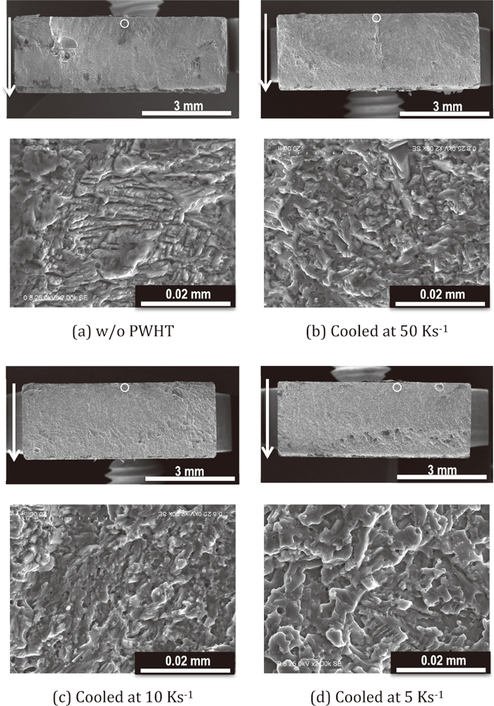
Fracture surfaces of the fatigue-failured specimens were examined in addition by SEM, and are shown in Fig. 9. The arrows in the low-magnification micrographs indicate the direction of crack propagation, and the microstructure of the regions close to the point of crack initiation, which are marked by the circles, are shown at high magnification. Striations indicating ductile fracture are observed in the specimen not subjected to the heat-treatment, Fig. 9(a), but not in the others. These observations are consistent with the reduction in the fatigue life in the heat-treated specimens, notwithstanding that one cannot discuss the details of cracking in the two-phase material.
4. Conclusions
Effects of post-weld heat treatment on the microstructure and fatigue strength of SDSS S32750 have been studied using a single-V welded joint, with the cooling rate from the solution-treatment temperature (1323 K) as the control parameter. The microstructure was examined by SEM-EBSD and optical microscopy, and fatigue properties were studied by plane-bending tests. The salient results are summarized as follows:
(1) The σ phase is formed in solution-treated specimens; its proportion is larger in specimens cooled at a lower rate, amounting to 20% in both the base metal and the weld metal at 0.1 K s−1.
(2) The hardness of the welded joint exhibits parallel variation to the amount of the σ phase, although not in good proportion to.
(3) Slow cooling from the solution-treatment temperature, which enhances precipitation of the σ phase, reduces fatigue life.
For the sake of reliability of welded joints, we conclude that post-weld heat treatments such as employed here shall not to be applied to weldments of this particular SDSS. If solution treatment is necessary for some reasons, the condition should be carefully selected.
References
- 1) K. Harada: Corros. Eng. (Jpn), 26 (1977), 721.
- 2) Duplex Stainless Steels: Microstructure, Properties and Applications, ed. by R. N. Gunn, Abington Publishing, Cambridge, UK, (1997).
- 3) J.-O. Nilsson: Mater. Sci. Technol., 8 (1992), 685.
- 4) Y. Maehara, M. Koike, N. Fujino and T. Kunitake: Tetsu-to-Hagané, 67 (1981), 577.
- 5) Y. Maehara, N. Fujino and T. Kunitake: Tetsu-to-Hagané, 68 (1982), 673.
- 6) J. K. Sahu, U. Krupp, R. N. Ghosh and J.-J. Christ: Mater. Sci. Eng. A, 508 (2009), 1.
- 7) M. Balbi, M. Avalos, A. El Bartali and I. Alvarez-Armas: Int. J. Fatigue, 31 (2009), 2006.
- 8) I. Alvarez-Armas, H. Knobbe, M. C. Marinelli, M. Balbi, S. Hereñú and U. Krupp: Procedia Eng., 10 (2011), 1491.
- 9) I. Alvarez-Armas, U. Krupp, M. Balbi, S. Hereñú, M. C. Marinelli and H. Knobbe: Int. J. Fatigue, 41 (2012), 95.
- 10) J. C. de Lacerda, L. C. Cândido and L. B. Godefroid: Int. J. Fatigue, 74 (2015), 81.
- 11) J. D. Kordatos, G. Fourlaris and G. Papadimitriou: Scr. Mater., 44 (2001), 401.
- 12) V. Muthupandi, P. Bala Srinivasan, S. K. Seshadri and S. Sundaresan: Mater. Sci. Eng. A, 358 (2003), 9.
- 13) R. Badji, M. Bouabdallah, B. Bacroix, C. Kahloun, K. Bettahar and N. Kherrouba: Mater. Sci. Eng. A, 496 (2008), 447.
- 14) Z. Zhang, H. Jing, L. Xu, Y. Han and L. Zhao: Mater. Des., 109 (2016), 670.
- 15) K. Devendranath Ramkumar, G. Thiruvengatam, S. P. Sudharsan, Debidutta Mishra, N. Arivazhagan and R. Sridhar: Mater. Des., 60 (2014), 125.
- 16) G. Chai and S. Johansson: Proc. 16th European Conf. Fracture, Part B, ed. by E. E. Gdoutos, Springer, The Netherlands, (2006), 193.
- 17) R. Udo, H. Nishikawa, H. Hato, K. Miyazaki, K. Masaki and H. Numakura: Tetsu-to-Hagané, 103 (2017), 202.