Abstract
In order to elucidate possible mechanism causing nozzle clogging during continuous casting of Ti added Ultra Low C (Ti-ULC) steel, thermodynamic analysis and experimental validation were carried out with an emphasis on the chemical reaction between the liquid steel and nozzle refractory. It was pointed out that the reaction occurs between CO gas from the nozzle refractory and the liquid steel, at the interface between them. A series of thermodynamic calculations were carried out in order to predict related phase equilibria. It was found that Ti in the steel induces the formation of a liquid oxide composed of FetO–Al2O3–TiOx along with solid alumina. This was different to a case of Ti-free ULC where only solid alumina was stable. In order to verify the thermodynamic predictions, a series of experiments were conducted. A number of Fe–Al–Ti alloys were reacted with CO gas at 1560°C in order to simulate the interfacial reaction. Surface and cross section of the alloy samples were analyzed using Scanning Electron Microscopy (SEM) with Energy Dispersive Spectrometry (EDS). The experimental results were in good agreement with the thermodynamic predictions. This finding provides an idea why nozzle clogging is deteriorated by addition of Ti in ULC steel. It is proposed that Ti is oxidized together with Fe and Al by CO gas from a nozzle, and forms a liquid oxide composed of FetO–Al2O3–TiOx, which shows good wettability both to liquid steel and to refractory. This would be a precursor of clog material inside the nozzle.
1. Introduction
Submerged Entry Nozzle (SEN) clogging is one of the major problems lowering quality of steel products and productivity during the continuous casting process. Nozzle clogging occurs often during casting of Al-killed Low Carbon (LC) steel and Ultra Low Carbon (ULC) steel.1) The clogging mechanism in Al-killed ULC steel was well established that the clogging is developed by two steps: network alumina formation and buildup of alumina inclusions suspending in liquid steel.1,2,3) The network alumina is formed on inner surface of a nozzle due to a reaction between dissolved Al in liquid steel and CO gas generated from the nozzle.1,2,4) Once the network alumina is formed, other alumina inclusions suspending in the liquid steel as a product of deoxidation move to the inner wall due to eddies induced by steel flow. The roughness of inner wall of the nozzle provides a favorable condition for the alumina inclusions to attach to the already formed network alumina layer.1) As this alumina adheres repeatedly, inner passage of the nozzle becomes narrower. Finally, it causes the nozzle clogging, followed by termination of the casting process. There are various solutions to suppress the nozzle clogging phenomena during continuous casting of Al-killed ULC steel such as argon bubble injection, enhancement of nozzle geometry, use of CaO based nozzle, etc.1,5)
On the other hand, when Ti is added to Al-killed ULC (Ti-ULC) steel, nozzle clogging becomes more serious than that of Ti-free ULC steel. Clog materials found in Ti-ULC steel casting is somewhat different to that observed in the case of Ti-free ULC steel casting.6) The reason for the deteriorated nozzle clogging has not been fully clarified yet. Several researchers have investigated the effect of Ti on the nozzle clogging of Ti-ULC steel casting.6,7,8,9) Distinctive difference between the two cases (Ti-free ULC steel casting vs Ti-ULC steel casting) is that clog material of the Ti-ULC steel casting is composed of frozen steel with dispersed alumina clusters,6,7) whereas that of Ti-free ULC steel casting is almost alumina1.1) Basu et al. reported that clog material of Ti-ULC steel casting was heavier and tougher than that of Ti-free ULC steel casting.6) Moreover, a large amount of frozen steel was observed, but Ti-bearing inclusions (“TiOx−Al2O3”) were observed at few locations for the former case. Some researchers agreed that nozzle clogging could be originated from the formation of Al–Ti–O inclusion, which has high wettability with liquid steel.7,10) It was also suggested that formation of Ti-containing oxide layer is responsible for adhesion of frozen steels to the nozzle wall.7,8)
On the other point of view, some researchers reported that Ti in liquid Fe lowers the surface tension of liquid Fe–Ti alloy or contact angle between alumina substrate and the liquid alloy.11,12,13) This may reduce interfacial tension between Ti-ULC steel and nozzle, and may promote good adhesion of the liquid steel to the nozzle. However, there were also a few reports that Ti does not lower the surface tension/contact angle.14,15,16) The previous observations might be attributed to possible contamination of Ti sample15) or impurities in alumina substrate used for the contact angle measurement.17) In particular, Bernhard and co-workers13,17) found during their contact angle measurement between Fe–Ti alloy and alumina substrate that using almost pure alumina substrate did not lower the contact angle noticeably, while using less pure alumina substrate lowered the contact angle significantly. In the latter study, they observed an intermediate phase formed at the interface, which was composed of “rich in Al, O, Fe and Ti”.13) However, the interfacial phase was not further analyzed.
On another direction, studies on oxide inclusion evolution in Ti-ULC steel were carried out.18,19,20,21,22,23) Some researchers reported that Al–Ti–O complex inclusions could be formed during deoxidation or reoxidation. The inclusions may have high wettability with liquid steel, and were observed inside the frozen steel.1,6,10) This may be responsible for the cause of nozzle clogging in Ti-ULC steel casting. However, it was not clear what type of inclusions could form in the steel. A number of thermodynamic researches were carried out in form of oxide stability diagram.19,20,21,24,25,26,27) Some reported complex Al–Ti oxide (Al2TiO5) forms,19,20) and the other reported liquid oxide could form.20,25,26,27) Although not all of these diagrams look the same, it can be read from those diagrams that stable phase of oxide inclusion in typical Ti-ULC steel (containing a few hundred ppm of Ti and Al, respectively) should be solid alumina only. This is not much different to the case of Ti-free ULC steel. Therefore, oxide inclusions by deoxidation/reoxidation could not explain the significant deterioration of nozzle clogging of Ti-ULC steel casting, and clog material composed of frozen steel mixed with alumina inclusion.
When observation of nozzle clogging material,6,8) discrepancies in surface tension/contact angle measurement,12,13,14,15,16) and oxide stability diagram of the Fe–Al–Ti–O system,19,20,21,24,25,26,27) it may be suggested that interfacial reaction between liquid Ti-ULC steel and nozzle refractory should be carefully considered. Forming interfacial phase would change adhesion character between the steel and the refractory. However, condition at the interface would be different to that in bulk liquid steel, in particular chemical composition of the steel. Also, phases newly formed at the interface would be different to what is usually known as “network alumina”. Since typical SEN is mainly Al2O3−SiO2−C type, it is known that CO gas could be generated because of direct reaction between SiO2 and C.1,2,3) However, to the best knowledge of the present authors, there was no study on the interfacial reaction between Ti-ULC steel and CO gas emitted from refractories.
In the present study, oxidation behavior of Ti-ULC steel by CO gas was investigated which simulates the interfacial reaction between Ti-ULC steel and nozzle refractory during continuous casting. A series of CALPHAD thermodynamic analyses were first carried out in order to understand stable phases at the interface. And experimental investigations were followed by oxidizing a number of Ti-ULC steel samples by CO gas. Importance of the findings to understand nozzle clogging of Ti-ULC steel is discussed.
1 This observation may not be valid if inner wall of the SEN is lined with CaO based material, which reacts with the alumina layer/inclusion to form liquid calcium aluminate.
2. Thermodynamic Analysis
In order to know what types of phases form at the interface, it is necessary to check phase diagrams of the system relevant to the present study. As the interfacial reaction occurs between Ti-ULC steel and CO gas generated from nozzle refractory, the present system may be represented by oxidation of liquid Fe–Al–Ti alloy. Therefore, the present system is confined to the Fe–Al–Ti–O system. Phase diagrams shown in the present article were obtained by CALPHAD thermodynamic calculations using FactSage and relevant thermodynamic databases.28) The thermodynamic databases have been prepared by a series of critical evaluation and thermodynamic optimizations. Details of database construction for the system relevant to the present study can be found elsewhere.25,26,27,29)
Ti-bearing inclusion was often expressed as “TiOx−Al2O3”. It should be noted that Ti is a transition metal, therefore, phase equilibria of Ti-containing oxide system depend significantly on oxygen partial pressure in a system. Figure 1 shows calculated phase diagram of (a) Al2O3−TiOx at pO2 = 0.21 atm (air), (b) Al2O3−TiOx at pO2 = 10−15 atm (reducing condition), and (c) Al2O3−TiOx at T = 1540°C. x−axis is a molar ratio of nTi/(nAl + nTi). Often referred complex inclusion “Al2TiO5” can be seen in Fig. 1(a) near casting temperature (approximately 1530 to 1550°C). However, the same phase is not shown in Fig. 1(b) where the corresponding pO2 is more relevant to the liquid steel. In fact, Fig. 1(c) is a phase diagram of Al–Ti–O system at a fixed temperature (1540°C) with pO2 as a y-axis. The Al2TiO5 is seen to be stable only pO2 > ~ 10−11.7 atm at this temperature. This is thought to be significantly higher than that in liquid steel. Therefore, temperature and oxygen partial pressure are determining factors of oxide stability in the present system.

It is suggested that all thermodynamic considerations be carried out under the condition of continuous casting, and local condition at the interface. Before the local condition is discussed, it is first checked what phases would form when Ti presents in ULC steel killed by Al.
2.1. Oxides in Fe–Al–Ti–O System
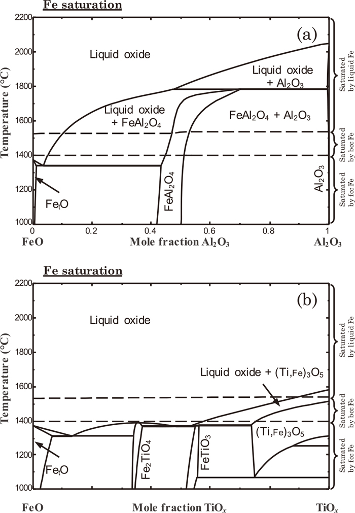
Phase diagrams of FetO–Al2O3 and FetO–TiOx systems were calculated, and are shown in Fig. 2. Since Fe and Ti are both transition metals, oxygen partial pressure should be set to correctly define phase equilibria. Figure 2 was obtained at metallic Fe saturation, which is thought to be close to a situation of oxide inclusion in liquid steel. Dashed lines in the figure were shown to indicate stable phases of the metallic Fe. When Al forms its own oxide, it is Al2O3 which is a solid near the casting temperature. Slight over-oxidation would result in the formation of FeAl2O4, which is still solid phase. On the other hand, when Ti forms its own oxide at metallic Fe saturation, it is a mixture of liquid oxide and (Ti, Fe)3O5 solid solution. The liquid oxide is composed of FetO–TiOx. This implies that when Ti-ULC steel is oxidized, there is a chance to form liquid oxide containing FetO–Al2O3–TiOx along with other solid oxides such as Al2O3 or (Ti, Fe)3O5.
In this regard, it is worthwhile to analyze an oxide stability diagram relevant to Ti-ULC steel. As the Ti-ULC steel may be simply represented by Fe–Al–Ti alloy, an oxide stability diagram of the Fe–Al–Ti–O system was considered. A recently reported diagram at 1540°C is shown in Fig. 3.26,27) Depending on the composition of the steel, different oxide phases can be stable. In a region marked “A”, which represents the composition of typical Ti-ULC steel, a stable oxide phase is seen to be Al2O3. Here, the composition would be understood as the bulk composition of the steel. Oxygen concentration is as low as a few mass ppm. On the other hand, a liquid oxide (composed of FetO–Al2O3–TiOx) can form in the region of high O region (marked as “B”) where the oxygen concentration is as high as a few hundred ppm. If a Ti-ULC steel is exposed to any oxidation condition, it would cause the formation of the liquid oxide. In the present study, it is considered that nozzle refractory would provide such oxidation environment, and the oxidation occurs at the interface between the nozzle and the liquid steel.

Generally, nozzle refractory is composed of Al2O3, SiO2 clinker, and flake type graphite. CO gas is generated by Reaction (1) from direct contact between SiO2 and graphite.1,2,3) The CO gas generated from inside of the nozzle migrates through open pores in the refractory toward its surface, and forms network alumina by Reaction (2) for normal Al-killed steel:1,2,3,4)
|
Si
O
2
(
s, refractory
)
+C(
s, refractory
)
=SiO(
g
)
+CO(
g
)
| (1) |
|
3CO(
g
)
+2
Al
_
=A
l
2
O
3
(
s
)
+3
C
_
| (2) |
Under thermodynamic equilibrium, SiC(s) is stable instead of SiO(g). Therefore, SiO(g) is a metastable species, and most part of the gas is almost CO(g).
In the Ti-ULC steel, the CO gas emitted from the refractory material can be a source of the oxidation at the interface. According to the discussion in Sec. 2.1, not only Al2O3 but also liquid oxide may form depending on the local composition of the steel near the interface. Then, it is reasonable to think that the steel passing through the nozzle is exposed to the CO gas, which could be a source of surface oxidation of the Ti-ULC.
2.3. Reaction between CO Gas and Fe–Al–Ti Alloys-Thermodynamic Prediction
It is worthwhile to observe what results from a reaction between Ti-ULC and CO gas at the casting condition (pressure and temperature at the interface between the steel and the nozzle inner wall). For the sake of simplicity, total pressure and temperature were assumed to be 1 atm, and 1540°C, respectively, but this is reasonable. Figure 4(a) shows a calculated phase diagram of the Fe–C–O system using FactSage.28) Concentrations of C and O in liquid Fe are shown where CO gas is in equilibrium with the liquid Fe. Three different conditions were considered. Most relevant condition to the casting condition is shown by a thick solid line. When CO gas is supplied to almost pure Fe surface (marked by an open circle), it dissolves into the liquid Fe and dissociates into C and O:

Then, concentrations of C and O at the interface increase keeping an equimolar ratio of C and O (ΔnC = ΔnO) until the liquid Fe is saturated by the CO gas. It is marked by a closed circle, where O concentration at the interface reaches up to 500 ppm, which is soluble concentration. In other words, assuming that the gas supplied from the refractory is almost CO, the O concentration in the vicinity of the refractory was expected to be around 20 times higher than those of the ULC steels (~20 ppm). The behavior of oxide formation at the interface with the higher local O concentration (represented by the closed circle) is thought to be dissimilar to that in bulk region (represented by the open circle). On the way from the bulk (open circle) to the interface (closed circle), concentrations of O and C, and oxygen partial pressure of the system were also calculated, and were shown in Figs 4(b) to 4(d), respectively. It can be understood that O concentration at the interface is significantly higher (where PCO is close to 1) than that in the bulk steel (where PCO is very low or close to zero), for which the latter information has been usually considered. It should be stressed that, in order to understand what happens at the interface, the local condition be considered.
From the above, it is postulated that chemical reactions relevant to form clog materials on the inner wall of SEN occur between Ti-ULC steel and CO gas at the casting condition. The clog materials should be found in the presence of CO gas in equilibrium with the steel (PCO = 1). Therefore, the above analysis is now extended to systems containing Al and/or Ti. Figure 5(a) shows a calculated phase diagram of Fe–Al–Ti–CO system at PCO = 1, T = 1540°C. x− and y-axes are mass fraction of Al and Ti over all metallic components ([pct Al]’ = WAl/(WFe + WAl + WTi), [pct Ti]’ = WTi/(WFe + WAl + WTi), respectively, where Wi = mass of i. These axes variables may be regarded as an initial composition of steel before it reacts with the CO gas. When the steel is in equilibrium with CO gas (PCO = 1), equilibrium phases can be read from the phase diagram. It can be seen that liquid oxide is always stable, and Al2O3 is also a stable phase when Al concentration is high. The liquid oxide is not stable only when Ti concentration is very low. Phase fractions of the liquid oxide and the Al2O3 were also calculated when [pct Ti]’ = 0.05, and are shown in Fig. 5(b). Increasing Al concentration increases the fraction of Al2O3, and decreases that of liquid oxide after the formation of Al2O3. A long-dashed line in the Fig. 5(a) is a Zero Phase Fraction line of Al2TiO5: upper right side of which the Al2TiO5 is a stable phase according to the thermodynamic calculation. Regarding the stability of the Al2TiO5, it is discussed in Sec. 4.2.

This analysis means that liquid oxide could form at the interface between Ti-ULC steel and nozzle refractory at casting condition. Furthermore, it should be noted that the liquid oxide contains FetO, which is known to adhere easily to refractory as well as to liquid steel. This may play as a precursor to cause building up clogging materials during continuous casting of Ti-ULC. It is worthy to note that the liquid oxide does not form when Ti concentration is low. This may be a possible reason why increasing Ti concentration in ULC steel deteriorates nozzle clogging during continuous casting. The thermodynamic prediction is validated in the present study, as will be discussed in Sec. 3.
3. Experimental
Oxidation of a number of Fe–Al–Ti alloys was conducted by blowing CO gas on the surface the alloys. Any oxide phases formed on the surface were analyzed and compared with the thermodynamic predictions shown in Sec. 2.3.
3.1. Sample Preparation
0.5 kg of electrolytic iron was charged into an MgO crucible and was melted at 1600°C in an induction melting furnace. In order to remove O as an impurity in the electrolytic iron, Ar-4 pct H2 gas mixture flowed over the molten iron for 4 hours. It was confirmed by LECO inert gas infrared absorption analysis that O in the iron was decreased to ~20 ppm. Six samples were prepared: pure Fe, Fe-0.05Al, Fe-0.05Ti, Fe-0.0125Al-0.05Ti, Fe-0.025Al-0.05Ti, and Fe-0.05Al-0.05Ti. Those samples were prepared by adding an appropriate amount of Ti sponge (99.9 mass pct., Kojundo, Japan) and/or Al pellet (5N grade, Kojundo, Japan) into the molten iron after lowering the O concentration. After homogenizing, samples were obtained by quarts tubes of 4 × 10⁻³ m inner diameter to obtain bars of the sample. The samples were cut into small pieces of (6 ± 1) × 10−4 kg. The surface of the samples was ground to remove any oxide film, before subsequent oxidation experiment.
3.2. Experimental Procedure and Analysis
Schematic figure of experimental apparatus is shown in Fig. 6(a). The sample was placed in a shallow alumina crucible (Fig. 6(b)), which is put in a quartz tube equipped with an RF generator (40 kW, 260 kHz). The tube was sealed by end caps in order to control atmospheric condition. Ar gas purified by passing through CaSO4 column, and MgO chips at 550°C flowed at 0.5 L min−1 through an inner quartz tube. Power of the RF generator was adjusted in order to set a temperature at 1560°C, which is 20°C higher than that used in Fig. 5 in order to ensure melting of the sample. Once the target temperature was achieved, the Ar gas was replaced by 0.5 L min−1 of CO gas, and oxidation of the sample started. After 30 minutes, the CO gas was switched back to Ar gas for purging, and the power was turned off in order to quench the sample. Obtained sample after the oxidation is shown in Fig. 6(c). The sample was gold-coated. Surface of the samples was analyzed using Scanning Electron Microscopy (SEM) with Energy Dispersive Spectrometry (EDS). After then, the sample was mounted with cold resin, cut into a vertical direction (Fig. 6(d)), and was subject to additional analysis by SEM-EDS in order to observe the cross section of the sample. More than ten points were analyzed, and average composition was obtained. C concentration from the EDS analysis was ignored as C solubility in oxide phase is usually very low. A preliminary test for a Fe-0.025Al-0.05Ti sample was reported elsewhere.30)

4. Results
4.1. Fe
Figure 7(a) shows surface of a sample of nearly pure Fe, after the reaction with CO. It looks clean with no oxide on the surface. The concentration of the surface was 84.25 (± 5.75), 4.25 (±1.90), and 9.38 (±3.71) (in mass pct) for Fe, O, and C, respectively, according to EDS analysis. Although the EDS does not provide accurate quantitative values for light elements such as O and C, the O concentration is higher than that of pure Fe before the reaction, but is lower than that of oxides. Any interfacial product was not detected in both surface and cross section by the SEM analyses. When the CO gas was dissociated on the sample by the Reaction (3), it is thought that the O concentration on the surface was locally increased, but no interfacial products were formed. This is consistent with the thermodynamic analysis shown in Fig. 4(a).
4.2. Fe-0.05Al
SEM images of surface and cross section of 0.05 pct Al containing sample are shown in Fig. 8. It is clear that a new phase was formed, and its thickness was ~2 μm. The concentration of the surface product was 4.05 (± 1.49) Fe, 44.64 (± 2.35) Al, 51.31 (± 3.10) O (in mass pct), respectively, according to EDS analysis. As predicted in Fig. 5, liquid steel should be in equilibrium with Al2O3, in the presence of CO (PCO = 1). Al in the liquid steel reacted with the CO gas to form solid Al2O3. The experimental observation is in good agreement with the thermodynamic prediction. This alumina corresponds to the network alumina, which is known to cause building up clog material inside nozzle.1)
4.3. Fe-0.05Ti
In Fig. 5, it was predicted that liquid oxide should form in the presence of CO for this sample. Figure 9 shows analyzed results of the Fe-0.05Ti sample after the oxidation. Surface of this sample was covered by a new phase. The concentration of the surface product was 29.54 (± 9.43) Fe, 37.00 (± 6.45) Ti, 31.69 (± 5.82) O, respectively, according to EDS analysis. Trace of Al (1.77 pct) was detected, and this might come from the alumina crucible. In EDS mapping analysis, dark phase (the surface product) in Fig. 9(a) showed higher intensity of Ti that that of bright phase. When it is compared with the thermodynamic analysis, it is thought that the surface product was FetO–TiOx liquid oxide. Surface of the surface product (dark phase) also looks smooth, contrary to that shown in Fig. 8(a). It suggests that the product was a liquid phase.
4.4. Fe-(0.0125, 0.025, 0.05)Al-0.05Ti
Figure 10 shows morphology, SEM image, and EDS mapping image of the surface of Fe-0.0125Al-0.05Ti sample after the oxidation. At a first glance of Fig. 10(a), the surface of this sample does not shine with metallic brightness, contrary to that can be seen in Fig. 7(a) where no oxide was formed. SEM image of the surface products looks to be composed of two parts, as can be seen in Fig. 7(b). Dark part looks like a facetted crystal, and bright part looks to fill the remaining part. The concentration of the bright part was 56.06 (± 8.38) Fe, 15.02 (± 3.08) Ti, 6.29 (± 0.85) Al, and 22.66 (± 3.54) O, respectively. EDS mapping analysis (Figs. 10(c) to 10(f)) showed that the dark phase has a high intensity of Al. On the contrary, high intensities of Ti and Fe were identified in the bright phase. It could be assumed that the dark phase was composed mostly of solid Al2O3, while the bright phase consisted of FetO–Al2O3–TiOx, which is a liquid phase at the casting condition. Increasing Al concentration (Fe-0.025Al-0.05Ti, Fe-0.05Al-0.05Ti) also resulted that surface of those samples were composed of both liquid oxide and solid Al2O3. Concentrations of the liquid oxides in a sample Fe-0.025Al-0.05Ti are 71.05 (± 2.72) Fe, 9.24 (± 0.70) Ti, 4.57 (± 1.61) Al, and 15.15 (± 1.81) O. Those of the other sample Fe-0.05Al-0.05Ti are 13.78 (± 5.10) Fe, 39.09 (± 2.50) Ti, 10.07 (± 1.77) Al, and 37.06 (± 3.31) O. Although this EDS analyzed concentrations are not considered quantitatively accurate, it is considered that these results in combination with the thermodynamic prediction (Fig. 5) support a fact that a liquid oxide composed of FetO–Al2O3–TiOx is formed by the reaction between Ti-ULC and CO gas.

Similar experimental results were reported by Sasai and co-workers who investigated oxidation behavior of Al−,31) Ti−32) and Ti–Al32) deoxidized molten steels under high oxygen partial pressure range (PO2 = 0.05–0.23 atm). Their research was focused on reoxidation behavior of molten steel in tundish by air. Therefore, the atmospheric condition in their study was more significantly oxidizing than that employed in the present study (PO2 = ~10−10 atm). They also observed that FetO-containing liquid oxide (and some portion of solid oxides) formed at the surface of the molten steels deoxidized by Ti or Ti–Al. Compared to their study, it was confirmed in the present study that even at PO2 = ~10−10 atm induced by CO gas, Ti in liquid steel easily oxidizes along with Fe and Al and forms liquid oxide composed of FetO–Al2O3–TiOx.
5. Discussions
5.1. Possible Clog Materials Formed at the Interface between Ti-ULC Steel and Nozzle Refractory
Dissolved Al and Ti in the Ti-ULC steel might react with CO gas supplied from nozzle refractory, and form a liquid oxide (FetO–Al2O3–TiOx) and solid Al2O3 simultaneously. Presence of Fe oxide in the liquid oxide at the interface may increase the wettability to both the refractory material and the liquid steel. It is well understood that liquid Fe oxide easily adheres to other materials including steel and oxide by lowering interfacial tension.33,34,35) The formation of FetO–Al2O3–TiOx liquid oxide makes a favorable condition for the refractory and the liquid steel to contact tightly each other. Since solid Al2O3 also forms together with the liquid oxide, there will be a mixture of the liquid oxide and the solid Al2O3. This mixture seems to work as a binder between the refractory and the liquid steel. Increasing binding force between alumina inclusions due to FetO was reported by Mizoguchi et al.36) A point to be noted is such liquid oxide containing FetO did not form when liquid steel does not contain Ti (Fe-0.05Al). In this case, only Al in the steel oxidizes to form Al2O3. This network alumina formation has been already known.1,2,3,4) On the other hand, increasing Ti concentration results in initiation of the liquid oxide formation, as was confirmed in the present study by thermodynamic analysis and experimental validation. As concentration of Al relative to Ti in the Ti-ULC steel increases, a portion of solid Al2O3 in the solid/liquid oxide mixture also increases. It means Ti is more harmful than Al because Ti triggers for Fe to be oxidized to form FetO containing liquid oxide. It is proposed that the formation of FetO–Al2O3–TiOx liquid oxide by reaction with CO gas from the nozzle refractory may be responsible to more serious nozzle clogging for Ti-ULC steel casting, compared to nozzle clogging of Ti-free Al-killed steel. Therefore, nozzle clogging mechanism in the Ti-ULC steel casting should be enlightened on the basis of the relationship between the FetO–Al2O3–TiOx liquid oxide and clogging materials.
Clogging materials in SEN used to cast Ti-ULC steel are usually composed of frozen steel with reticulated TiOx−Al2O3 layer and Al2O3 clusters.6,7) Since wettability of the FetO-containing liquid oxide with liquid steel is high,33) the liquid steel can be readily adhered on the surface of the nozzle by forming the FetO–Al2O3–TiOx layer. Then, it may be proposed based on practical operation7,37) that the clogging mechanism would be those shown Fig. 11: the TiOx−Al2O3 layer might be originated from a reduction of the FetO–Al2O3–TiOx liquid oxide. FetO in the liquid oxide could be reduced by Al (and Ti) in liquid steel or C in the nozzle refractory. In addition, the TiOx−Al2O3 layer is able to retain attachment of liquid steel/refractory since TiOx has low interfacial tension with Fe compared to pure Al2O3.1) Consequently, the liquid oxide works as an intermediate product due to an instability of FetO in liquid oxide during practical operation. The reduced Fe from the FetO may be an origin of the frozen steel found as a part of clogging material. It may be considered that the reduced Fe induce further solidification of the liquid steel passing through the SEN. Thermal conductivity values of Fe is in the order of ~10−1 W m−1 K−1, while that of Ar gas and Al2O3 are ~10−6 and 10−4 W m−1 K−1, respectively, near the temperature of the present investigation.38,39) As a conventional clog material is the alumina clusters, which may be in contact with Ar gas due to Ar gas injection into the SEN, the heat transfer in the presence of the reduced Fe is likely to be enhanced. Then, heat extraction rate towards the atmosphere around the SEN becomes higher. This is considered to be reasonable for a part of the SEN above mold flux that is in contact with open atmosphere. Proposed clogging mechanism is schematically shown in Fig. 11. On the other hand, the other part of the SEN below meniscus is in contact with the liquid steel in the casting mold. In such circumstance, the heat extraction rate would not be high. It requires further investigation in order to verify the formation of frozen steel.

During the thermodynamic calculation in Fig. 5, Al2TiO5 was predicted to be one of the stable phases at certain condition (upper right side of a long dashed line in Fig. 5(a), which is a Zero Phase Fraction line of Al2TiO5). According to this prediction, the Al2TiO5 should be observed in Fe-0.05Al-0.05Ti sample. However, this phase was not observed in the present study. This may be due to a low thermodynamic stability of this phase, requiring a longer time to be sintered and be densified.40) Although it was not certain whether the solid phase is a true Al2TiO5 or not, it is consistent with a report that additives such as MgO and ZrO2, which exists in the nozzle refractory as impurities, enhances sintering and densification of Al2TiO5, thereby making it more stable. Therefore, Al2TiO5 may form under some favorable condition, controlled partially by a kinetic factor.
As can be seen in Fig. 1, the Al2TiO5 should be a stable phase at higher oxygen partial pressure. Nevertheless, Sasai and co-worker also did not report that Al2TiO5 was observed in Ti–Al deoxidized molten steel oxidized at high PO2 condition.32) Therefore, it is thought that Al2TiO5 phase is not an easily forming phase, and it was not considered in the present study.
5.3. C Concentration in Liquid Steel and Interface Oxidation
According to the proposal in the present study, the formation of the liquid oxide due to oxidation by CO gas is related to nozzle clogging Ti-ULC steel casting. Nozzle clogging is generally serious for ULC steel where a mixture of alumina inclusion and frozen steel is often observed. On the other hand, nozzle clogging by such mixture is relatively less serious when C concentration in steel is high. This is thought that presence of the C could lower activity of O in liquid steel. This further lowers driving force to form the liquid oxide. Recent thermodynamic investigation on the construction of oxide stability diagram showed that increasing C concentration in liquid steel suppresses formation of such liquid oxide composed of FetO.41) Instead of the liquid oxide, CO gas appears as a stable oxide phase. An example of oxide stability diagram of high C steel is shown in Fig. 12. C concentration is intentionally set to 0.5 pct. for the sake of demonstration. As can be seen, CO gas is a stable phase instead of liquid oxide, contrary to the case shown in Fig. 3. Consequently, the clogging mechanism shown in Fig. 11 may not be relevant to a case of high C steel casting.

The present study is in line with a relevant investigation of Fukuda et al.4) They reported that the network alumina formation on the nozzle surface decreased by increasing C concentration in Al-killed steel. Since total O concentration was very low due to the high C concentration, occurrence of Al pickup was suppressed.4)
To summarize, the nozzle clogging during continuous casting of Ti-ULC steel is known to be caused by a mixture of frozen steel and alumina inclusion (with few Ti containing inclusions). This seems to be a result of the formation of liquid oxide composed of FetO–Al2O3–TiOx, reduced by Al in liquid steel or C in refractory. The formation of liquid oxide is caused by CO gas generated from nozzle refractory and is possible when C concentration in the steel is very low such as in ULC steel. However, when C concentration is high, oxidation of the liquid steel is suppressed due to the high C concentration.
6. Conclusions
In order to elucidate the mechanism of nozzle clogging in SEN during continuous casting of Ti-ULC steel, a series of thermodynamic analysis and experimental validation were carried out. It was focused on oxidation of liquid steel by CO gas generated from the nozzle refractory. By comparing the thermodynamic prediction with results of experiments for the interfacial reaction between CO gas and steel, following conclusions have been obtained.
(1) CO gas generated from nozzle refractory dissolves in liquid steel, and local O concentration can be increased. This leads to various oxide formation at the interface between the nozzle and the liquid steel.
(2) When liquid steel contains only Al (Fe-0.05Al), Al2O3 was generated by a reaction with CO gas. When liquid steel contains only Ti (Fe-0.05Ti), the liquid oxide was produced which is composed of FetO–TiOx. When liquid steel contains both Al and Ti (Fe-(0.0125,0.025,0.05)Al-0.05Ti), a mixture of liquid oxide composed of FetO–Al2O3–TiOx and solid Al2O3 was produced. This was confirmed by thermodynamic analysis and laboratory scale oxidation experiments.
(3) The liquid FetO–Al2O3–TiOx oxide has high wettability with both the liquid steel and the nozzle refractory, and it provides a good contact between the liquid steel and the refractory.
This liquid oxide seems to play as a precursor of the nozzle clogging. It is not detected in SEN after practical operation. This may be attributed to a hypothesis that Fe oxide in the liquid oxide might be reduced by Al in the Ti-ULC steel or C in the nozzle refractory. This leaves reduced Fe and Al2O3–TiOx. This hypothesis should be further investigated.
In order to mitigate nozzle clogging in continuous casting of Ti-ULC steel, oxidation of the liquid steel by CO gas at the interface between the nozzle and the liquid steel needs to be suppressed.
Acknowledgment
This research was financially supported by POSCO. Valuable discussions with Mr. Sang-Woo Han and Mr. Janghoon Kim, Technical Research Laboratories, POSCO, Rep. of Korea, Prof. J. Lee, Korea University, Rep. of Korea, and Prof. C. Bernhard, Montanuniversität Leoben, Austria are appreciated. Constructive comments from the reviewer are also well appreciated.
References
- 1) S. Ogibayashi: Taikabutsu Overseas, 15 (1995), 3.
- 2) K. Sasai and Y. Mizukami: ISIJ Int., 34 (1994), 802.
- 3) K. Sasai and Y. Mizukami: ISIJ Int., 35 (1995), 26.
- 4) Y. Fukuda, Y. Ueshima and S. Mizoguchi: ISIJ Int., 32 (1992), 164.
- 5) K. G. Rackers and B. G. Thomas: Proc. 78th Steelmaking Conf., ISS, Warrendale, PA, (1995), 723.
- 6) S. Basu, S. K. Choudhary and N. U. Girase: ISIJ Int., 44 (2004), 1653.
- 7) Y. Hiraga, Y. Yashima and K. Fujii: Taikabutsu Overseas, 15 (1995), 22.
- 8) H. Cui, Y. Bao, M. Wang and W. Wu: Int. J. Miner. Metall. Mater., 17 (2010), No. 2, 154.
- 9) K. Sasai and Y. Mizukami: J. Tech. Assoc. Refract. Jpn., 23 (2003), 156.
- 10) P. Kaushik, R. Lule, G. Castillo, J. Delgado, F. Lopez, C. Perim, G. Pigatti, B. Henriques, F. Barbosa and A. Nascimento: AIST Trans., 13 (2016), 168.
- 11) M. Kishimoto, K. Mori and Y. Kawai: J. Jpn. Inst. Met., 48 (1984), 413.
- 12) S. Ueda, A.W. Cramb, H. Shi, X. Jiang and H. Shibata: Metall. Mater. Trans. B, 34 (2003), 503.
- 13) A. Karasangabo and C. Bernhard: J. Adhes. Sci. Technol., 26 (2012), 1141.
- 14) L. A. Smirnov, S. I. Popel’ and B. V. Tsarevskii: Izv. VUZ. Chernaya Metall., 3 (1965), 10.
- 15) J. Lee, A. Kiyose, M. Tanaka and T. Tanaka: ISIJ Int., 46 (2006), 467.
- 16) K. Mukai, L. Zhong and M. Zeze: Proc. 12th ISIJ-VDEh Seminar, ISIJ, Tokyo, (2005), 177.
- 17) C. Bernhard, G. Xia, M. Egger, A. Pissenberger and S. K. Michelic: Proc. Iron & Steel Technology Conf. and Exposition (AISTech) 2012, AIST, Warrendale, PA, (2012), 2191.
- 18) M. Van-Ende, M. Guo, R. Dekkers, M. Burty, J. Van-Dyck, P. Jones, B. Blanpain and P. Wallants: ISIJ Int., 49 (2009), 1133.
- 19) H. Matsuura, C. Wang, G. H. Wen and S. Sridhar: ISIJ Int., 47 (2007), 1265.
- 20) F. Rudy-Meyer, J. Lehmann and H. Gaye: Scand. J. Metall., 29 (2000), 206.
- 21) W.-Y. Kim, J.-O. Jo, C.-O. Lee, D.-S. Kim and J.-J. Park: ISIJ Int., 48 (2008), 17.
- 22) C. Wang, N. T. Nuhfer and S. Sridhar: Metall. Mater. Trans. B, 41B (2010), 1084.
- 23) M.-K. Sun, I.-H. Jung and H.-G. Lee: Met. Mater. Int., 14 (2008), 791.
- 24) I.-H. Jung, S. A. Decterov and A. D. Pelton: ISIJ Int., 44 (2004), 527.
- 25) I.-H. Jung, G. Eriksson, P. Wu and A. D. Pelton: ISIJ Int., 49 (2009), 1290.
- 26) Y.-B. Kang and J.-H. Lee: ISIJ Int., 57 (2017), 1665.
- 27) Y.-B. Kang and J.-H. Lee: ISIJ Int., 57 (2017), 2269.
- 28) C. W. Bale, E. Bélisle, P. Chartrand, S. A. Decterov, G. Eriksson, A. E. Gheribi, K. Hack, I.-H. Jung, Y.-B. Kang, J. Melançon, A. D. Pelton, S. Petersen, C. Robelin, J. Sangster, P. Spencer and M.-A. Van Ende: Calphad, 54 (2016), 35.
- 29) I.-H. Jung, S. Decterov and A. D. Pelton: Metall. Mater. Trans. B, 35B (2004), 493.
- 30) J.-H. Lee, S.-K. Kim, M.-H. Kang and Y.-B. Kang: Berg- und Hüttenmännische Monatshefte, 163 (2018), 18.
- 31) K. Sasai and Y. Mizukami: ISIJ Int., 36 (1996), 388.
- 32) K. Sasai and A. Matsuzawa: ISIJ Int., 52 (2012), 831.
- 33) K. Ogino, S. Hara, T. Miwa and S. Kimoto: Trans. Iron Steel Inst. Jpn., 24 (1984), 522.
- 34) A. W. Cramb and I. Jimbo: Iron Steelmaker Trans., 11 (1989), 43.
- 35) S.-C. Park, H. Gaye and H.-G. Lee: Ironmaking Steelmaking, 36 (2009), 9.
- 36) T. Mizoguchi, Y. Ueshima, M. Sugiyama and K. Mizukami: ISIJ Int., 53 (2013), 639.
- 37) W.-G. Jung, O.-D. Kwon and M.-K. Cho: Korean J. Mater. Res., 19 (2009), 473.
- 38) R. W. Powell, C. Y. Ho and P. E. Liley: Thermal Conductivity of Selected Materials, National Standard Reference Data Series – National Bureau of Standards, U.S. Government Printing Office, Washington D.C., (1966), 35.
- 39) R. W. Powell, C. Y. Ho and P. E. Liley: Thermal Conductivity of Selected Materials, National Standard Reference Data Series – National Bureau of Standards, U.S. Government Printing Office, Washington D.C., (1966), 139.
- 40) C. G. Shi and I. M. Low: Mater. Res. Bull., 33 (1998), 817.
- 41) Y.-B. Kang and S.-H. Jung: ISIJ Int., 58 (2018), in press.


