Abstract
Hot-core Heavy Reduction Rolling (HHR2) is an innovative technology designed for eliminating center defects of blooms, which provides heavy reduction to blooms with two-high mill after solidification at the end of the strand. This works mainly focus on design and optimization of work roll profile that apply specifically to HHR2 process to obtain the best effect on shrinkage closing. Firstly, hot rolling experiment and corresponding finite element calculation were carried out. Based on the experiment and FEM results, the void closure model was established to describe the behavior of shrinkage closing. Secondly, this model was used in analyzing the effects of different roll profiles on void closure during HHR2 process. The result shows that the convex profile and box groove profile had better effects than flat profile and parabolic profile, which can provide greater value of effective strain and smaller value of stress triaxiality respectively. Finally, a new roll profile for HHR2 was designed by combining both geometrical features of convex profile and box groove profile. The rational value scope of convex width coefficient θ and convex height coefficient γ were optimized to achieve a better effect on eliminating shrinkage cavities.
1. Introduction
The high quality of blooms are prerequisite for high performance rolled products, because they are the key raw materials for hot rolling. Shrinkage cavities and porosities are the main defects forming at the center position of blooms during continuous casting process. At present, hot rolling and hot forging are the common method for eliminating the shrinkage cavities,1,2,3) and the compression ratio must be sufficient to achieve the closure effect,4,5) especially for the bloom with large section.
In recent decades, some technologies were proposed to alleviate center defects, which mainly included soft reduction and heavy reduction process that performed compression deformation to blooms where the center metal were in mushy zone. The soft reduction technology is mainly to solve segregation defect,6,7) which the solid fraction at the core of the bloom is 0.3 to 0.8.8) The heavy reduction process such as Porosity Control of Casting Slab technology (PCCS) of Sumitomo Metal in Japan,9,10) Heavy Reduction technology (HR) proposed by Zhu11,12) and POSCO Heavy strAnd Reduction Process technology (PosHARP)13) can accumulate greater central deformation of blooms or slabs, which the solid fraction of core metal is 0.8 to 1.0. In addition, the heavy reduction process can decrease the formation of shrinkage cavity, and promote solute mass transfer to solve the segregation problem.14) In these technologies, the deformation of core metal is in the mushy zone, but the brittleness temperature range (BTR) is also in this range,15,16) thus the internal cracks easily formed in those heavy reduction process above. Besides, these technologies mainly adopted multi-pass compression to improve the quality of bloom. However, according to the results of Zhao,17) the single-pass heavy reduction process is more effective than the multi-pass process in promoting void closure. Recently, based on the study of soft reduction and heavy reduction process, a new technology was proposed, referred as Hot-core Heavy Reduction Rolling (HHR2), which provided a single-pass heavy reduction to bloom with two-high mill after solidification at the end of the strand. For the Hot-core Heavy Reduction Rolling process, the core metal of bloom have fully solidified that the risk of internal cracks is greatly reduced. In addition, because of the application of single-pass heavy reduction, HHR2 process is expected having better effect on void closure.
In order to describe the behavior of void closure quantitatively during HHR2 process, the influential factors and relevant methods should be understood first. At present, a large number of studies on the void closure in hot forging and hot rolling process had been carried out by researchers. For the hot forging process, numerous parameters were studied in their works, such as the stroke,18) the reduction schedule19,20) and temperature gradient of workpiece.21) Tanaka et al.18) found that the void closure is related to the time integral of hydrostatic stress and effective strain, by combining finite element analysis and experiment. For hot rolling, the studies on void closure were focused on the effects of rolling schedule, reduction rate and rolling speed.22,23) More remarkable, the surface profile of die is also a key factor affecting the evolution of void closure during hot forging.24) Similarly, a new roll contour called convex profile was designed for PosHARP to eliminate the core defects of bloom, which had a convex in the middle of the flat roll. The industry application showed that shrinkage and segregation defects were improved obviously by using the convex roll.25,26) Understandably, the void closure of HHR2 should be also affected by the surface profile of roller. The aim of this paper is to design an appropriate roll profile especially for HHR2 for eliminating the shrinkage cavities of bloom. For this aim, hot rolling experiment and relevantly finite element calculation were used in creating model to describe evolution of void volume quantitatively. Then, this model was applied to analyzing the effects of different roll surface profiles on void closure. Ultimately, the FEM was used to confirm the best roll profile design for achieving the best effect on elimination of the shrinkage cavities during HHR2 process.
2. Evolution Model for Void Closure
Usually, the shrinkage is inconsecutive and irregular, which present as banding distributed at the core of blooms. The diameters of the shrinkage cavities at the cross section of bloom are non-uniform ranged from less than a millimeter to several millimeters, and this difference are caused by the steel composition, size of bloom and technical level of metallurgical process, and so on. In order to explore the evolution of voids quantitatively during HHR2 process, the hot rolling experiment with presetting holes at the core of blooms were performed. Then, the corresponding finite element model was established for analysis based on the experiment conditions. According to the experiment and simulation results, void closure model was established to reflect the volume variation of voids in practical hot rolling.
2.1. Experiment Procedure
The composition of blooms was C-0.098, Si-0.051, Mn-1.52, P-0.040, S-0.016, Cr-0.28, Ni-0.60, Al-0.028, Cu-0.264, Ti-0.009, Nb-0.022 and Fe-balance (wt%). Blooms with a length of 600 mm and a cross section of 132 × 132 mm were selected as the workpiece for hot rolling experiment. Cylindroid holes with different diameters were set at the core position of blooms in advance. The specific machining process and assembly could be describe as follows:
(1) Large cylindrical holes were drilled at the center of both sides of the bloom along the centerline, as shown in Fig. 1(a). The diameter of holes were 45 mm with a length of 260 mm.

(2) The inserts that were designed as perforated cylinders and non-perforated cylinders were interference fit with the large cylindrical hole of blooms. The inserts and blooms were used with the same steel grade. As shown in Fig. 1(b), at the center of perforated cylinders, the through-holes were drilled with diameter range of 4 mm to 8 mm. The aim of setting different size of holes can describe as follows. Firstly, it add the number of comparison tests for obtaining the universal regression model and reducing the accidental experimental error. Secondly, it can be used to reflect the influence of size of shrinkage cavities on its shape evolutions during hot rolling process. Thirdly, the bigger holes with diameter of 6–8 mm are easily measured and have the lower error. In addition, the through-holes smaller than 3 mm are hard machined, and the corresponding FEM is difficultly calculated because of the increasing number of mesh.
(3) The perforated cylinders were buried deeply inside the bloom to ensure that they were in steady rolling state during hot rolling experiment. While the non-perforated ones were assembled at the outermost position that not only fixed internal cylinders, but diminished impact to the internal cylinders in bite stage and tailing-out stage. The specific information of blooms was listed in Table 1, and the schematic diagram is drawn in Fig. 1(c).
Table 1. Specification of bloom and working condition of mill.
| Bloom | | Mill | |
|---|
| Size | 132 × 132 × 550 mm | victory | 0.2 m/s |
| Large size hole | Φ45 × 260 mm | reduction | 10, 16, 22 mm |
| Perforated cylinder | Φ45 × 60 mm | Roll diameter | 750 mm |
| Not Perforated cylinder | Φ45 × 140 mm | Surface temperature | 1010°C |
| Thermometer holes | Φ6.5 × 66 mm | Core temperature | 1151°C |
| Distance between thermo-holes | 19 mm | | |
(4) The thermometer holes were drilled with the same depth at the middle position of blooms, which were designed for measuring internal temperature through thermocouples.
After assembly, blooms were put into the reheating furnace. The holding time was 5 hours for obtaining uniform temperature at 1200°C. After transporting the workpiece, thermocouples were inserted in the thermometer holes for temperature data acquisition rapidly. The temperature data were continuously recorded by LOGGER GL240 that the data sampling frequency was 10 Hz. Meanwhile, the surface temperature was monitored by Non-contact Infrared Thermometer, and the emissivity was defined as 0.7. As the surface and center temperatures fall to 1010°C and 1151°C respectively, the blooms were sent to the mill for hot rolling. The rolling conditions are listed in Table 1.
After rolling, each perforated cylinder zone was cut into 20 slices along cross section with linear cutting, and the statistics of outline of void were gathered. What needs to be emphasized is that cutting in this way is used to reserve the data of void in thickness direction and spread direction precisely.
2.2. The FEM Analysis of Hot Rolling Experiment
Finite element analysis was also used for analyzing the evolution of voids closure during hot rolling experiment process. A three dimensional thermo-mechanical coupled hot rolling model was established by using the DEFORM-3D software based on the experimental process. The roller was defined as rigid body, while bloom was defined as visco-plastic body.
Heat radiation and heat exchange with work roll were considered in this model. The value of emissivity was defined as 0.7, which was a slightly smaller than the value in the condition of industrial production. This is because a thicker oxide scale caused by the long time heating is exist at the surface of workpiece during temperature measurement of hot rolling experiment. The heat transfer coefficient between work roll and bloom were quoted from the results by Tang.27) Moreover, friction coefficient between work roll and bloom was defined as 0.3.28,29) In this model, cylinder holes were set at the core of workpiece. Tetrahedral elements are used in meshing the bloom, which shows in Fig. 2, and the number of elements is 248002.

In order to accurately characterize the distribution of stress and strain during HHR2, compression experiment was completed in Gleeble-3800 simulator. The test temperature range and strain rate were 800–1350°C and 0.01–5 s−1 respectively, which covered all the deformation conditions of hot rolling experiments and HHR2. The Hansel-Spittel model30) was used to describe the flow stress dependency on the temperature, strain and strain rate. The material coefficients was identified through non-linear regression, shown in Eq. (1). The correlation coefficients R of the model was 0.989, and the contrast between experimental curves and the model data were presented in Fig. 3.
|
σ=27.49
e
-0.0035T
ε
0.00428
ε
˙
-0.391
e
-0.000011
ε
(
1+ε
)
-0.000913T
e
0.00012ε
ε
˙
0.00042T
T
0.932
| (1) |
The temperature distribution was the critical factor to void closure, so the evolution of temperature field was calculated primarily. The temperature distribution at the entrance of the mill is revealed in Fig. 4, which also shows that the measured data are consistent with simulation results. In the cross section, the temperature gradient along the thickness direction increase gradually from the sides to middle part of bloom. By aforementioned work, it ensures the reliability of simulation, which provide practical initial temperature field for the further study.

After hot rolling experiment, the void was fusiform on the cross section of blooms, which were measured with low magnification microscopic. The Fig. 5 shows the comparison results of geometric outline of the voids between numerical simulation and experiment, when the reduction is 22 mm. In addition, the sizes of long axis and short axis of the fusiform voids were compared with simulation results, as drawn in Fig. 6, which consistent with the FEM results that well reflect the evolution of void during hot rolling experiment.
2.3. Evaluation Model of Void Closure in Hot Rolling
According to the results of Tanaka et al.,16) the void closure of hot forging could be compared and predicted by using void closure evaluation index Gm (shown in Eq. (2)), which was the function of mean stress, effective stress and effective strain.
|
G
m
=∫
0
ε
f
(-
σ
m
/
σ
eq
)d
ε
eq
=
∑
t=1
n
(-
σ
m
/
σ
eq
)
t
Δε
eq
t
| (2) |
Where
σm is mean stress, MPa,
σeq is effective stress, MPa,
εeq is effective strain,
εf is Critical effective strain,
t is the number of analysis step.
The value of Gm increase with the void tending to closing, and this conclusion is widely used for analyzing the behavior of void closure in hot deformation. It reflects that the behavior of void closure is related to the general stress and strain states at core position of continuous bloom. The value of Gm can be used as evaluation index for void closure, but it cannot reflect the 3-D geometric variation directly during hot deformation. In addition, Zhang et al.31) and Feng et al.32) proved that Norton exponent n was a key material parameter relating to void evolution by using representative volume element (RVE) model. For nonlinear viscous material, Norton exponent is represented as Eq. (3). So, one of the aims of this paper is to create a model to describe void closure during hot rolling and HHR2 based on Gm, εeq and n.
|
1
n
=
d(
ln
σ
eq
)
d(
ln
ε
˙
eq
)
=
|
∂(
ln
σ
eq
)
∂(
ln
ε
˙
eq
)
|
ε, T
| (3) |
Where
ε
˙
eq
is effective strain-rate.
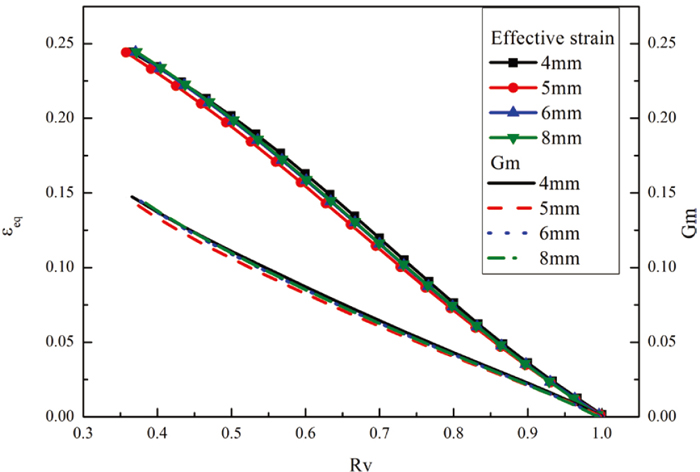
Volumetric residual rate RV is the ratio of void volume after hot rolling and that in initial, which is usually used as the quantitative index in describing the void evolution. When the reduction is fixed, the relationships between RV and Gm as well as RV and εeq are shown in Fig. 7. It reveals that the voids with different sizes can obtain similar variation tendency of Gm and εeq, which means the behavior of void have little relationship with diameter of void, when the void size is small enough relative to the bloom size. The Fig. 8 reflects that the values of RV, Gm and εeq increase with the reduction rate increasing. In addition, when a heavier reduction is performed in hot rolling process, the absolute value of gradient
|
∂
R
V
/∂
ε
eq
|
gets greater and the absolute value gradient
|
∂
R
V
/∂
G
m
|
gets smaller.
Based on the results of RV and the corresponding FEM results, a new model of RV was created to describe the evolution of void closure quantitatively. RV was defined as the function of effective strain, void closure evaluation index and Norton exponent, which were shown in Eq. (4). The model coefficients were obtained by using nonlinear regression method, and the value of c1– c6 were 61.49, 0.014, 1.91, −6.37, −62.19 and 0.0076. The fitting effects is reflected in Fig. 9. The correlation coefficients R was 0.998 and the value of RMSE was 1.25%.
|
R
V
=
V
V
0
=exp(
c
1
⋅
(
G
m
n
)
c
2
⋅
ε
eq
c
3
+
c
4
⋅
G
m
+
c
5
⋅
ε
eq
2
+
c
6
)
| (4) |
3. The Continuous Casting Temperature Field and Modeling of HHR2
During the process of Hot-core Heavy Reduction Rolling, a two-high mill was installed after solidification end of the strand that provided single-pass heavy reduction to blooms, as shown in Fig. 10(a). The roll surface profile had a significantly effect on the evolution of void closure. So, in the study, four basic roll surface profiles were designed and compared, including flat profile, parabolic profile, convex profile and box groove profile, which were shown as Figs. 10(b)–10(e). The Numerical simulation were used, which the calculation model was established based on the actual production conditions at a 3-strand bloom caster with the section of 300 mm × 360 mm in Chinese HBIS Group SHISTEEL Company. Shrinkage cavities are the common defects in their product, and its diameter at cross section usually ranges from 1 to 5 mm.

Temperature field of continuous casting is the basic of Hot-core Heavy Reduction Rolling process, therefore the temperature evolution was calculated with fully considered the secondary cooling and heat radiation process. The temperature evolution of key positions of bloom is shown in Fig. 11. Meanwhile, the actual temperature data at the narrow surface center and corner of blooms are measured by thermal imager FLIR SC620 with setting the value of emissivity as 0.8, and this value is match the production conditions. The Fig. 12 is one of infrared images obtained from the on-line production, and all the temperature data reading from images are indicated in Fig. 11. Obviously, the predicted results and measured results are consistent at the corresponding positions, and it lay the foundation for the further prediction of hot rolling.

The temperature difference between the core and surface of bloom falls fast from 430°C at the exit of second tension leveler stretcher to 78°C at the finishing position of flame-cutting. Visually, the temperature difference can form a relatively chilled outer shell with a certain thickness outside the blooms. Besides, the shell are thicker when the position is closer to the solidification end, which also promote the deformation of core metal because of a greater difference of rheological properties. Thus, the mill is arranged at the exit of last tension leveler stretcher where the core and upper surface temperature of bloom are 1303.8°C and 995.3°C respectively.
Based on the result of continuous casting temperature field, the thermo-mechanical coupled model were established. The four basic roll surface profiles were modeled to explore effective roll profiles. During hot rolling, all the work rolls had the same roll gap at the middle position of roll surface, and the value was 260 mm. The diameter of work roll at the middle position were defined as 950 mm.
4. Results and Discussion
4.1. Effect of Roll Surface Profiles on Void Closure
The void closure evaluation index Gm was used for qualitatively contrast and mechanical analysis, which was calculated by secondary development of the software. Meanwhile, the RV was utilized in quantitative prediction of volume evolution during HHR2 process.
The Gm distribution of the blooms at the outlet section of mill were shown in Fig. 13. The values of Gm at the core position of blooms were 0.142, 0.141, 0.169 and 0.165, when the flat profile, parabolic profile, convex profile and box groove profile were used, respectively. According to the accepted conclusion that the degree of void closure had a positive correlation with Gm, so the convex roll and box groove roll should have a better effect on void closure at the core position of blooms. In addition, the convex profile and parabolic profile have projecting portion radially outward, but they obtain the opposite results when the same roll gap are performed to the blooms, which shows the unique effect of convex profile.

Closure evaluation index is equal to the integral of the opposite of stress triaxiality ratio (η = σm/σeq, the rate of mean stress and effective stress) over the cumulated strain, which means void closure relate to the stress state and the level of effective strain simultaneously. As shown in Fig. 14, when these four kinds of roll profiles work during HHR2 process, the overall trend is that the value of stress triaxiality are negative and the effective strain increase gradually at the core position of bloom. According to the Eq. (2), it can have good effect on void closure if there are lower stress triaxiality or a greater growth rate of effective strain during hot rolling process. The Fig. 14 also shows that convex profile had the greatest effective strain, but had undistinguished level of stress triaxiality. Conversely, the box groove profile could obtain outstanding stress triaxiality compared with other roll profiles. In other words, convex profile and box groove profile can provide excellent strain state and stress state respectively, which means both roll profiles have complementary strengths in promoting void closure.

On one hand, the box groove profile limits lateral spread during HHR2, and it forms a greater compressive stress to the core of bloom along the width direction, so the mean stress decreased. On the other hand, two possible reasons are proposed to explain why the convex roll can form greater strain at the core. Convex roll can form stress concentration at the middle zone of blooms, which promotes core deformation, and this was also mentioned in MOON Chang Ho’s work.26) Meanwhile the surface temperature of blooms was lower than the core, which amount to forming a hard shell outside the bloom, so the middle zone of blooms was unsubstantial because of the thinner shell. When the convex roll works, the combined action of hard shell and convex roll may form torque taking the corner of convex as the fulcrum. When an appropriate convex width is confirmed, it can promote metal flowing to the core of bloom to benefit void closure.
The values of RV are revealed in Fig. 15. After HHR2 process with box groove profile and convex profile working, they are 20.1% and 20.8% respectively, which prove the smaller volumes can be obtained by using this two profiles comparing with the plat and parabolic profiles.
4.2. Optimal Design of Roll Surface Profile
The above result shows that the convex profile and box groove profile had better effects than the other profiles, which have complementary strengths in promoting void closure. Therefore, the design idea is to composite the geometrical features of both profiles for designing a more effective roll surface profile, which is shown in Fig. 16. This design is especially for HHR2 process of blooms with the cross section of 300 mm × 360 mm. As shown in the schematic, Wc and Wb are convex width and bloom width respectively, and Hmin and Hmax are corresponding to the minimal and maximal roll gap during HHR2. The other geometrical features such as round radius of convex parts and fillet radius of box parts are also reflected in Fig. 16.

In older to achieve better effect on void closure during HHR2, the geometrical features of roll surface profile should be further optimized. Two key shape coefficients called convex width coefficient θ and convex height coefficient γ were created for optimization. Convex width coefficient is defined as the ratio of convex width and bloom width, and convex height coefficient is defined as the ratio of the maximal and minimal roll gap of the convex roll. It means convex width increase with θ increasing, and the convex height decrease with γ increasing. A mountain of simulation were carried out with the purpose of obtaining the rational range of geometrical parameters for roll contour.
The influence of convex width on void closure is shown in Fig. 17. It reveals the tendency between effective strain and θ as well as Gm and θ. In this calculation, the convex height are all defined as 15 mm, and reduction at middle position of work roll is 40 mm. At the core zone of bloom, the effective strain and Gm value shows a similar trend that increase first and then decrease with the convex width increasing. when θ ranged from 0.5 to 0.7, it can acquire a good effect on void closure. Moreover, when the value of θ is around 0.66, the maximum of Gm is obtained.

The relationship between Gm and γ as well as effective strain and γ are reflected in Fig. 18 to describe the influence of convex height on void closure, which the convex width and reduction at the middle position of roll are 240 mm and 70 mm respectively. The effective strain and Gm raise with increasing of convex height. Therefore, the convex height should be designed as large as possible, when the rolling process and equipment are admissible.
Considered the rational range of geometrical parameters comprehensively, the convex width and convex height was defined as 240 mm and 20 mm, respectively.
4.3. Verification of the Optimized Effect
Based on the optimized design, the FE calculation was carried out for verifying the effect of the new optimized roll contour on void closure, and the evolution of residual volume ratio (RV) was also used for quantitative analysis. The Fig. 19 reveals that the void volume decreases fastest when the optimized roll works. Meanwhile the optimized roll profile can obtain the smallest value of RV with 10.27%, which is 14.22%, 8.33% and 8.86% smaller than the value of flat roll, box groove roll and convex roll.

Furthermore, cylinder holes were set at the core position of workpieces to verify direct-viewing effect on void closure, by FE calculation of HHR2 process. The diameter of cylinder hole were 4 mm. The Fig. 20 reflects that the convex profile have good effect on void closure along thickness directions, while the box groove profile can promote void closure in width direction. Under the same rolling conditions, the optimized roll profile can bring both superiorities of convex profile and box groove profile into full play.
5. Conclusion
(1) Hot rolling experiment was carried out with blooms, and some cylindroid holes of different diameters were set at the core position of bloom in advance. After hot rolling, the statistical data of geometric characteristics of holes were collected, and the corresponding finite element calculation was also used in analyzing this experiment process. The predicted results and measured results had good consistency. Based on the statistical data of FEM and experiment, a new model was proposed for analysis of void closure during HHR2 process, which was a function of void closure evaluation index Gm, effective strain and Norton exponent.
(2) The void closure model and relevant evaluation indexes were used in prediction of HHR2 process depending on a 3-strand bloom caster with the section of 300 mm × 360 mm. Based on the reliable continuous casting temperature field, the effect of different roll surface profiles on the void closure were compared. The result reflects that the box groove profile and convex profile have complementary strengths in promoting void closure, which can provide outstanding stress state and strain state respectively.
(3) The convex width coefficient θ and convex height coefficient γ were created, and the rational value scope of them were confirmed by FEM calculation. Based on this results, an optimized roller contour was designed especially for HHR2 process, which combined the profile characteristics of box groove profile and convex profile.
Acknowledgements
This authors gratefully acknowledge the support from the National Key Research and Development Program of China (No. 2017YFB0304603), and the help of technical support engineers from Hebei Iron and Steel Group of China.
References
- 1) B. G. Thomas: Metall. Mater. Trans. B, 33 (2002), 795.
- 2) A. Ghosh: Sadhana, 26 (2001), 5.
- 3) J. Brimacombe and K. Sorimachi: Metall. Mater. Trans. B, 8 (1977), 489.
- 4) S. Watanabe and T. Kunitake: Tetsu-to-Hagané, 61 (1975), 828 (in Japanese).
- 5) D. Bhattacharya: J. Mater. Eng. Perform., 3 (1994), 484.
- 6) Y. Tsuchida, M. Nakada, I. Sugawara, S. Miyahara, K. Murakami and S. Tokushige: ISIJ Int., 24 (1984), 899.
- 7) R. Thome and K. Harste: ISIJ Int., 46 (2006), 1839.
- 8) C. H. Yim, J. K. Park, B. D. You and S. M. Yang: ISIJ Int., 36 (1996), S231.
- 9) S. Hiraki, A. Yamanaka, Y. Shirai, Y. Satou and S. Kumakura: Materia Jpn., 48 (2009), 20 (in Japanese).
- 10) S. Hiraki, A. Yamanaka, T. Murakami and S. Kumakura: Continuous Casting Method, Continuous Casting Apparatus and Continuously Cast Steel Slab, U.S. Patent 7086450, (2006)
- 11) C. Ji, C.-h. Wu and M.-y. Zhu: JOM, 68 (2016), 3107.
- 12) C. Wu, C. Ji and M. Zhu: Steel Res. Int., 88 (2017), 1600514.
- 13) C. H. Yim, Y. M. Won, J. K. Park and S. H. Kwon: Continuous Cast Slab and Method for Manufacturing the Same, U.S. Patent 8245760, (2012).
- 14) Q. Dong, J. Zhang, B. Wang and X. Zhao: J. Mater. Process. Technol., 238 (2016), 81.
- 15) D. J. Seol, Y. M. Won, K. H. Oh, Y. C. Shin and C. H. Yim: ISIJ Int., 40 (2000), 356.
- 16) Y. M. Won, T.-J. Yeo, D. J. Seol and K. H. Oh: Metall. Mater. Trans. B, 31 (2000), 779.
- 17) X. Zhao, J. Zhang, S. Lei and Y. Wang: Steel Res. Int., 85 (2014), 1533.
- 18) S.-i. Ono, K. Minami, T. Ochiai, T. Iwadate and S.-i. Nakata: Trans. Jpn. Soc. Mech. Eng., 61 (1995), 2141 (in Japanese).
- 19) H. Kakimoto, T. Arikawa, Y. Takahashi, T. Tanaka and Y. Imaida: J. Mater. Process. Technol., 210 (2010), 415.
- 20) K. Mouri, T. Arima, M. Fukuya and T. Terasaki: J. Jpn. Soc. Technol. Plast., 57 (2016), 462 (in Japanese).
- 21) S. I. Ono, K. Minami, E. Murai and T. Iwadate: Trans. Jpn. Soc. Mech. Eng., 62 (1996), 1139 (in Japanese).
- 22) M. Nakasaki, I. Takasu and H. Utsunomiya: J. Mater. Process. Technol., 177 (2006), 521.
- 23) A. Wang, P. Thomson and P. D. Hodgson: J. Mater. Process. Technol., 60 (1996), 95.
- 24) S.-i. Ono, K. Minami, H. Iwasawa, T. Iwadate and S.-i. Nakata: Trans. Jpn. Soc. Mech. Eng., 61 (1995), 3437 (in Japanese).
- 25) J.-p. Zhao, L. Liu, W.-w. Wang, W.-j. Zhou and H. Lu: Ironmaking Steelmaking, 44 (2017), 1.
- 26) C. H. Moon, K. S. Oh, J. D. Lee, S. J. Lee and Y. Lee: ISIJ Int., 52 (2012), 1266.
- 27) G. B. Tang, Z. D. Liu, Y. L. Kang, W. Wang and P. J. Zhang: Iron Steel, 41 (2006), 36 (in Chinese).
- 28) P. Theocaris, C. Stassinakis and A. Mamalis: Int. J. Mech. Sci., 25 (1983), 833.
- 29) J. G. Lenard and L. Barbulovic-Nad: J. Tribol., 124 (2002), 840.
- 30) H. Arno and T. Spittel: Kraft-und Arbeitsbedarf Bildsomer Formgeburgs Verfahren, VEB Deutscher Verlang fur Grundstoffindustrie, Lipsk, (1979), 1 (in German).
- 31) X.-X. Zhang, Z.-S. Cui, W. Chen and Y. Li: J. Mater. Process. Technol., 209 (2009), 1950.
- 32) C. Feng and Z. Cui: Int. J. Plast., 74 (2015), 192.


