Abstract
Medium manganese steel (Fe-5.0%Mn-1.2%Si-0.10%C alloy) was subjected to interrupted quenching from the austenite single-phase region to a temperature between Ms and Mf followed by intercritical annealing in the ferrite and austenite dual-phase region at 923 K. As a result, a core-shell type second phase, which consisted of a fresh martensite core surrounded by a film-like retained austenite shell, was formed. The mechanism and kinetics of reversion for the interrupted-quenched specimens were analyzed with DICTRA simulation and TEM observation. With regard to the effect of the core-shell type second phase on mechanical properties, it was inferred that the fresh martensite core functioned as a hard second phase and enhanced work hardening by stress partitioning similar to DP steel, while the film-like retained austenite contributed to improved ductility due to the TRIP effect. As the interrupted quenching temperature decreased, the volume fraction of the fresh martensite core decreased, while the stability of the retained austenite shell increased. This showed potential for controlling the strength and ductility balance of medium manganese steel. A possible beneficial effect of the core-shell type second phase on the ductile fracture behavior was also discussed in terms of stress/strain relaxation at the interfaces between hard martensite and ferrite matrix.
1. Introduction
Medium manganese steel, a low-carbon steel containing 3–10% Mn, is regarded as a new-generation, high-strength, structural material. This steel exhibits excellent strength-ductility balance derived from the TRIP effect due to retained austenite in which Mn and C are concentrated during intercritical annealing (IA).1,2,3,4,5,6,7,8,9) To obtain excellent mechanical properties of medium Mn steel by ensuring that the TRIP effect is continued to the high-strain region, it is essential to increase the volume fraction of retained austenite, as well as improve its stability against deformation. To achieve this, a sufficient degree of partitioning of Mn from ferrite to reversed austenite is necessary. Therefore, IA has been carried out at approximately 900 K, at which Mn diffusion occurred. In the case of IA at 923 K for 5%Mn-0.1%C steel,1) film-like reversed austenite formed along lath boundaries and grew under the partition local equilibrium (PLE) mode.7,8,9) As a result, the retained austenite was found to contain concentrated carbon, as well as approximately 10% Mn. On the other hand, IA at such a high temperature markedly enhanced the recovery of the martensite matrix. The dislocation density was significantly decreased, and almost all the carbon in martensite was partitioned into austenite, which led to a marked deterioration in the matrix strength. In other words, the more the stability of retained austenite is increased, the more the matrix hardness is lowered.
The present authors proposed a modified process, interrupted quenching and intercritical annealing (IQ-IA),1) which enabled the stability of retained austenite to increase by high-temperature annealing without losing high-strength, even in simple 5%Mn-0.1%C steel. In this process, IA was performed at approximately 900 K under the coexistence of martensite and untransformed austenite after the first IQ between the Ms and Mf temperatures. During IA, the reversed austenite grew in both width and length. As the annealing temperature was not high enough for the long-range diffusion of Mn, Mn enrichment occurred only in the space swept by the moving austenite/martensite interface. Thus, the Mn in the original part remained average in concentration.1) After cooling to ambient temperature, the Mn-enriched region remained as austenite, while the Mn-non-enriched original austenite region transformed to martenite (fresh martensite). This resulted in the formation of a unique core-shell type second phase, which consisted of a fresh martensite core surrounded by a film-like retained austenite shell. This microstructure control led to considerable strengthening by fresh martensite containing high-density dislocations, as well as condensed carbon, although the previously formed martensite was recovered progressively. In addition, the retained austenite, sufficiently stabilized by the IA, improved the ductility of the steel through the TRIP effect. Recently, a similar heat treatment was conducted with Fe-0.2%C-8%Mn-2%Al medium Mn steel to investigate the detailed microstructure formation behavior and increased tensile strength.9)
To further examine this type of steel, the microstructure and mechanical properties of 5%Mn-0.1%C steel were studied under different IQ temperatures. The amount of fresh martensite is expected to be varied corresponding to that of untransformed austenite which is dependent on the IQ temperature. Therefore, the tensile strength of steels could be controlled by varying the IQ temperature. The volume fraction and stability of retained austenite and the partitioning behavior of Mn were also clarified. Finally, the advantage of the core-shell type second phase in ductile fracture will be discussed in terms of the void nucleation behavior during tensile deformation.
2. Experimental Procedure
The chemical composition of the steel used in this study is shown in Table 1. The specimen is one of the simplest medium Mn steels available: Fe-5Mn-1.2Si-0.1C alloy (mass%). Silicon was added to suppress cementite precipitation during heat treatment. The Ms and Mf temperatures of this steel were measured at 600 K and approximately 370 K by dilatometry, respectively. In this study, two kinds of heat treatments were applied to the specimens:
(I) Interrupted quenching and intercritical annealing (IQ-IA)
The specimens were solution-treated at 1173 K in the austenite single-phase region for 1.8 ks, followed by IQ in a salt bath held at different temperatures between Ms and Mf at 461 K, 518 K, and 546 K. Then, the specimens were kept there for 60 s so that each volume fraction of untransformed austenite could become approximately 10, 20, and 30 vol%, respectively. After that, the specimens were moved to another salt bath held at 923 K for IA and kept there for various times up to 100 ks, followed by water quenching to ambient temperature. The IQ temperatures for the control of austenite volume fraction were determined in advance by dilatation tests completed beforehand.
(II) Full quenching and intercritical annealing (FQ-IA)
The specimens were solution-treated at 1173 K in the austenite single-phase region for 1.8 ks and then fully quenched (FQ) in water to ambient temperature. The quenched specimens were immediately sub-zero-treated at 77 K for 1.8 ks to eliminate retained austenite. The quenched specimens were then subjected to IA at 923 K with a salt bath, followed by water quenching.
Table 1. Chemical composition of the steel used in this study (mass%).
| C | Si | Mn | P | S | Al | N | O | Fe |
|---|
| 0.10 | 1.19 | 5.0 | 0.003 | 0.002 | 0.017 | 0.0013 | 0.0010 | Bal. |
Changes in the phase transformation ratio during IA at 923 K were estimated by dilatation tests using a Formaster-F dilatometer (Fuji Electronic Industrial Co., Ltd.) with rod-like specimens (ϕ3×10 mm). The heat pattern for the dilatation tests was simulated similarly to the heat treatments of the specimens shown above, namely (I) and (II), though the sub-zero treatment was impossible to simulate in the dilatation tests. The heating and cooling rates in the simulation were set at 10 K/s and 100 K/s, respectively. Following the final quenching, the volume fraction of the retained austenite was estimated by saturation magnetization measurements at ambient temperature.10) The microstructure was analyzed with an optical microscope, as well as a transmission electron microscope (TEM). The partitioning of Mn was evaluated via energy-dispersive X-ray spectroscopy (EDS) analysis using scanning transmission electron microscopy (STEM, JEM-ARM200F). Tensile tests were conducted on test pieces, with gauge dimensions of 6 mm × 3 mm × 1 mm, using an Instron testing machine at an initial strain rate of 5.56 × 10⁻⁴/s.
3. Results and Discussion
3.1. Reversion Behavior of Interrupted-quenched (IQ) and Fully Quenched (FQ) Specimens
Figure 1 shows the changes in volume fractions of all austenite at 923 K including untransformed austenite formed by IQ (a) and the reversed austenite newly formed during IA at 923 K (b) in each specimen. The broken line drawn in Fig. 1(a) denotes the equilibrium volume fraction of austenite at the temperature calculated with Thermo-Calc using the SSOL 2 database. The initial volume fractions for the 461 K, 518 K, and 546 K-IQ specimens were 10, 19, and 28 vol%, respectively. These values correspond to the amounts of untransformed austenite in the as-IQ specimens. The volume fraction of austenite increased with increasing IA time in all specimens in a similar manner. However, the increment rate was different in each specimen; the larger the initial volume fraction was, the lower the increment rate became, and the FQ specimen exhibited the highest increment rate. It is inferred that this tendency might be due to the difference in the driving force for martensite to austenite reversion transformation because the free energy in the system should be relatively closer to the equilibrium with increasing the initial volume fraction of untransformed austenite.

To generalize and optimize the heat treatment condition of the FQ and IQ specimens, the reversion behaviors were simulated by the diffusion module (DICTRA). In a fully martensitic 5%Mn-0.1%C steel, the reversion behavior during IA is successfully modelled using DICTRA by Wei7) and Nakada,8) under the assumption that the local equilibrium condition holds at the ferrite/austenite interface. Although their models are simple one-directional growth models for an austenite nucleus, the changes in growth rate and element distribution are validly simulated. Therefore, by referring to their models, IQ specimens with different initial austenite volume fraction were simulated with DICTRA. The initial conditions of IA set before the calculation are shown in Fig. 2. In this calculation, the thermodynamic and diffusion data of martensite were substituted with those of ferrite. The cell length was set at 500 nm, which corresponded to one-half of the observed lath width, 1 μm. The initial austenite width was set at 50 nm and 150 nm for 461 K-IQ and 546 K-IQ specimens, respectively, with consideration given to their initial volume fraction of untransformed austenite. Under the above conditions, the calculation resulted in the change in the volume fraction of austenite in each specimen as represented in Fig. 3, where the results were drawn against the logarithmic scale to the near-equilibrium state (a) and against the linear scale in the range observed in this study (b). In Fig. 3(a), a critical point showing the transition of the reversion mechanism from NPLE to PLE appeared quickly around 10−3 s in each specimen as indicated by the arrows. This transition was reported in a fully martensitic 5%Mn-0.1%C steel,8) and our results revealed that the IQ specimen also exhibited the transition. The volume fraction of austenite of these specimens began to increase at approximately 100 s, overcame an equilibrium fraction of 36%, and then decreased again after attaining the peak fraction. More than 106 s was required to reach the equilibrium state. Although the peak volume fraction depended on the initial volume fraction, there was no significant difference in the time to reach the peak and the equilibrium state among the specimens. By comparing Fig. 3(b) with the experimental results shown in Fig. 1(a), we confirmed that the DICTRA simulation reproduced the actual reversion behavior of the IQ specimen, although it used the simpler one-directional growth model of Fig. 2. Figure 4 shows the changes in the concentration profiles of Mn and C during the IA in both 461 K-IQ and 546 K-IQ specimens, which were also calculated with DICTRA simulation. Since the local equilibrium holds at the ferrite/austenite interface under the PLE mode in the presented results, the Mn concentration at the interface in the austenite side rose to approximately 9%. However, low diffusivity of the Mn atoms at the IA temperature of 923 K resulted in the non-changeable Mn concentration in the center part of the initial austenite phase; the austenite remained at the original concentration of 5% Mn even after long-term IA for 10 ks with the width of 20 to 30 nm for the 461 K-IQ specimen and approximately 100 nm for the 546 K-IQ specimen. We concluded that Mn partitioning only takes place in the newly formed austenite region swept by the interface and that the Mn-enriched austenite would retain stability after cooling to ambient temperature, while the center part with lower Mn concentration should transform to martensite upon cooling after IA. As a result, the core-shell type second phase, which is composed of the fresh martensite core and retained austenite shell, is formed after IQ and IA.

Figure 5 presents optical micrographs of specimens fully quenched (a) and interrupted-quenched at 461 K (b), 518 K (c), and 546 K (d), followed by subsequent IA at 923 K for 10 ks. It was hard to distinguish reversed austenite in the micrographs; nevertheless, they should have various amounts of reversed austenite depending on their heat treatment routes. Figure 6 shows the change in the volume fraction of retained austenite measured at ambient temperature after the final IA treatment as a function of IA treatment time. Although the volume fraction of austenite increased with the IA treatment time in any specimen, different incremental behavior was observed between FQ and IQ specimens. The FQ specimen exhibited a relatively rapid increment from 0 to 25% in the 100 ks treatment, while the IQ specimens contained a greater percentage of retained austenite from the initial stage of IA, which gradually attained maximum values depending on the IQ temperature. It should be noted that the volume fraction of retained austenite became larger with a decreased IQ temperature, although the fraction measured at the IA temperature was smaller with a decreased IQ temperature as shown in Fig. 1(a). After a 10 ks IA treatment, the increment of austenite either leveled-off or tended to be slightly decreased. The results obtained signify that the stability of austenite at the IA temperature is lowered by increasing its volume fraction, which was mainly due to the dilution of carbon concentration. As shown in the DICTRA simulation in Fig. 4, the carbon concentration of the retained austenite shell is lower in the 546 K-IQ specimen than in the 461 K-IQ specimen by approximately 0.07 mass%, which corresponds to a rise in Ms temperature of 30 K.11) The results of Figs. 6 and 1(a) are represented together in Fig. 7 to compare the volume fractions of austenite measured at the IA temperature and at ambient temperature, where the difference between them corresponded to the volume fraction of fresh martensite formed by quenching after IA treatment. With an increased IQ temperature, the amount of fresh martensite is markedly increased. From the information gathered, we were able to control the amount of fresh martensite by varying the IQ temperature; thus, the strength of the steel could be changed.


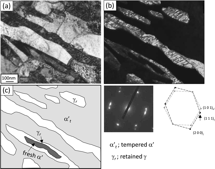
TEM bright-field and dark-field images with diffraction patterns for each specimen are presented in Figs. 8, 9, 10. Traces of TEM images are also shown to highlight the complex microstructure. The FQ specimen (Fig. 8) exhibited the typical lath-like retained austenite with a width of 200 to 500 nm distributed within tempered martensite. The dislocation density of the tempered martensite was extremely lowered due to the elevated temperature and long-term IA treatment. The austenite in this specimen should lie along the lath boundary of the initial quenched martensite. However, two IQ specimens (Figs. 9 and 10) had the core-shell type second phase, where the fresh martensite grain with high-density dislocations is surrounded by film-like austenite, in addition to the normal lath-like retained austenite grains. We confirmed that the volume fraction and size of the fresh martensite were larger in the 546 K-IQ specimen (Fig. 10) than in the 461 K-IQ specimen (Fig. 9), and that they inherited the distribution of the untransformed austenite formed by IQ. The width of the film-like austenite was 100 nm or less, which corresponded well with the calculation results in Fig. 4. Theoretically, it should be wider in the 461 K-IQ specimen because the growth rate of the newly formed austenite region swept by the interface became higher with a decreased IQ temperature; however, it was hard to confirm with mere two-dimensional observation. The distribution of Mn concentration in the IQ-IA specimens was then examined by STEM-EDS analysis. The results for the 461 K and 546 K-IQ specimens are presented in Fig. 11. In both Mn mappings for the 461 K-IQ (a) and 546 K-IQ (b) specimens, the shell parts with high concentration, core parts with medium concentration, and matrices with low concentration were clearly visible; they roughly corresponded to retained austenite, fresh martensite, and tempered martensite, respectively. From the line analysis results crossing the core-shell type second phase, quantitative Mn distribution was confirmed. Here, the initial concentration of 5% is shown with broken lines. As the thickness of the Mn-enriched layer was almost constant under the same IA condition, the width of the core part varied depending on the IQ temperature. In a small core-shell type second phase with less than 100 nm width such as grain (1), the Mn concentration reached the maximum value of approximately 9% in the center of the retained austenite. This could be a newly nucleated austenite formed during IA, similar to the FQ specimens. In the case of grain (2), the Mn concentration increased to approximately 8%, even in the center; however, it did not reach peak value but was slightly convex downward. This indicated that either Mn diffusion reached the center due to its small size, or that the top surface of a large core-shell type second phase might have been cut in the TEM thin foil specimen. When the size of austenite was sufficiently large, a clear core-shell type second phase was formed, as in grains (3) and (4). These results corresponded well with the results calculated by DICTRA simulation, suggesting that the growth of austenite underwent the interfacial equilibrium of the PLE mode.

Nominal stress-strain curves of specimens obtained in this study with the IQ-IA process are shown in Fig. 12. For reference, a result from an FQ-IA processed specimen is indicated by the gray line. As the IA treatment was fixed at 923 K for 10 ks, the volume fraction of each structure is found at the right vertical axis of Fig. 7. All specimens exhibited round-house-type yielding similar to conventional DP steels. We found that IQ markedly improved the strength, particularly when a higher IQ temperature was selected. For example, the tensile strength of the 546 K-IQ specimen reached 1127 MPa, which is 1.4 times higher than that of the FQ-IA specimen. Although the elongation of IQ-IA specimens was lower than that of the FQ-IA specimen, it should be noted that the local elongation was decreased very little. We investigated the tensile property of a conventional DP steel without retained austenite in our previous study and found that the tensile strength and elongation were 947 MPa and 12.5%, respectively.12) Comparing these results revealed that IQ-IA processed medium Mn steel had a significantly greater strength-ductility balance due to the TRIP effect working with stable retained austenite, as well as strengthening due to hard fresh martensite. Figure 13(a) shows the changes in the volume fraction of retained austenite in the IQ-IA processed specimens during tensile testing as a function of nominal strain. To evaluate the mechanical stability of retained austenite, the vertical and horizontal axes were converted into a logarithm of volume fraction and true strain, respectively, as shown in Fig. 13(b). According to Sugimoto,13) the k values (namely, the slopes of these lines) can be used as an index of austenite stability in the following equation:
|
log
f
γ
=-kε+log
f
i
γ
| (1) |
where
ε is the true strain, and
f
i
γ
and
fγ are the volume fractions of austenite at the initial state and at the true strain of
ε, respectively. With decreased
k, it was determined that the stability of austenite increased. As shown in
Fig. 13(b), the 461 K-IQ specimen had the smallest
k value, and thus, the highest mechanical stability among the three specimens. This may be due to it having the highest carbon concentration in the retained austenite, which resulted from the smallest volume fraction of austenite at the IA temperature. With knowledge obtained from these results, we can control the strength level as well as the stability of austenite with the volume fraction of fresh martensite as a function of the IQ temperature.


The unique morphology of the core-shell type second phase could be reflected on the effect of its mechanical properties, especially the ductile fracture behavior or local elongation, which is related to void formation. In conventional DP steel, it is widely known that tensile deformation leads to the formation of microvoids at or near the interfaces between hard martensite and the ferrite matrix, which induces early stage fracture through void coarsening and connection.12) In the case of the core-shell-structured medium Mn steels produced in this study, the fresh martensite contributed to work hardening much like DP steel, but retained austenite existed at its interface and caused stress- or strain-induced transformation during tensile deformation. This may have caused a beneficial effect on the ductile fracture behavior through stress/strain relaxation at the interfaces between hard martensite and the ferrite matrix. In fact, fewer and smaller-sized voids tended to form in IQ-IA processed specimens compared with the previously reported DP steel. However, this needs to be ascertained in future studies.
4. Conclusions
(1) The IQ-IA process for medium manganese steel (Fe-5%Mn-1.2%Si-0.1%C alloy) resulted in the formation of a core-shell type second phase consisting of fresh martensite (core) surrounded by a retained austenite film (shell) within a tempered martensite matrix.
(2) The core-shell type second phase was formed by the growth of untransformed austenite during IA, where Mn enrichment took place only in the shell, which was swept by the moving austenite/martensite interface, while the Mn concentration at the core was maintained near the initial concentration of 5%.
(3) By increasing the IQ temperature, the volume fraction and size of untransformed austenite increased; thus, the volume fraction and size of fresh martensite also increased. On the other hand, the volume fraction of retained austenite and its stability decreased when the IQ temperature was increased due to dilution of carbon concentration in the austenite.
(4) The IQ-IA-processed steel exhibited superior strength-ductility balance to that of conventional DP steel due to the TRIP effect. The tensile strength of this steel depended upon the volume fraction of fresh martensite; therefore, its tensile strength can be changed by the IQ temperature.
Acknowledgement
This work was supported by JSPS KAKENHI Grant Number JP17H01333.
References
- 1) T. Tsuchiyama, T. Inoue, J. Tobata, D. Akama and S. Takaki: Scr. Mater., 122 (2016), 36. https://doi.org/10.1016/j.scriptamat.2016.05.019
- 2) Y.-K. Lee and J. Han: Mater. Sci. Technol., 31 (2015), 843. https://doi.org/10.1179/1743284714Y.0000000722
- 3) T. Furukawa and O. Matsumura: Netsu Shori (J. Jpn. Soc. Heat Treat.), 37 (1997), 204 (in Japanese).
- 4) D.-W. Suh, S.-J. Park, T.-H. Lee, C.-S. Oh and S.-J. Kim: Metall. Mater. Trans. A, 41 (2010), 397. https://doi.org/10.1007/s11661-009-0124-7
- 5) T. Hanamura, S. Torizuka, A. Sunahara, M. Imagumbai and H. Takechi: ISIJ Int., 51 (2011), 685. https://doi.org/10.2355/isijinternational.51.685
- 6) H. F. Xu, J. Zhao, W. Q. Cao, J. Shi, C. Y. Wang, C. Wang, J. Li and H. Don: Mater. Sci. Eng. A, 532 (2012), 435. https://doi.org/10.1016/j.msea.2011.11.009
- 7) R. Wei, M. Enomoto, R. Hadian, H. S. Zurob and G. R. Purdy: Acta Mater., 61 (2013), 697. https://doi.org/10.1016/j.actamat.2012.10.019
- 8) N. Nakada, K. Mizutani, T. Tsuchiyama and S. Takaki: Acta Mater., 65 (2014), 251. https://doi.org/10.1016/j.actamat.2013.10.067
- 9) R. Ding, Z. Dai, M. Huang, Z. Yang, C. Zhang and H. Chen: Acta Mater., 147 (2018), 59. https://doi.org/10.1016/j.actamat.2018.01.009
- 10) T. Hara, H. Goto and S. Takaki: Netsu Shori (J. Jpn. Soc. Heat Treat.), 36 (1996), 322 (in Japanese).
- 11) R. W. K. Honeycombe and H. K. D. H. Bhadeshia: Steels: Microstructure and Properties, 2nd ed., Butterworth-Heinemann, Oxford, UK, (2000), 103.
- 12) K. Park, M. Nishiyama, N. Nakada, T. Tsuchiyama and S. Takaki: Mater. Sci. Eng. A, 604 (2014), 135. https://doi.org/10.1016/j.msea.2014.02.058
- 13) K. Sugimoto, N. Usui, M. Kobayashi and S. Hashimoto: ISIJ Int., 32 (1992), 1311. https://doi.org/10.2355/isijinternational.32.1311