Abstract
Dissolved gas flotation method has been developed to remove inclusions in molten steel. The principle is that bubbles formed on inclusions by vacuum treatment of nitrogen or hydrogen supersaturated molten steel can carry the inclusions to slag. A kinetic model was constructed to analyze the bubble growth and floating behavior during the degassing process of the method, and its accuracy was verified by related experiments. The results show that pretreatment pressure, bubble nucleation depth and gas type have significant effects on bubble growth and floating, while vacuum treatment pressure and inclusion radius have little effects on it. The growth rate and floating velocity of bubbles increase with the increase of pretreatment pressure or the decrease of bubble nucleation depth. The growth rate and floating velocity of hydrogen bubbles are much larger than those of nitrogen bubbles. Calculation results indicate that the diameters of the bubbles are mostly 0.2–10 mm during floating process via this method. Moreover, the distribution of the bubbles nucleating on the inclusions is dispersive. In addition to the bubbles carrying inclusions to slag directly, these dispersive fine bubbles have a high probability of inclusion adhesion resulting in an improvement of the inclusion removal.
1. Introduction
Non-metallic inclusions have great effects on the quality and performance of steel. Controlling the amount of inclusions in molten steel is usually regarded as a key factor for improving the quality of steel. Several refining methods have been developed in recent years to improve the cleanliness of steel. Among them, gas refining methods have been concerned and developed due to the less pollution to molten steel and good inclusion removal effect.1,2,3,4,5,6,7,8,9,10,11)
When molten steel was treated by gas refining methods, inclusions are removed by the adhesion and wake flow of bubbles. Wang12) established a mathematical model for the probability of inclusions adhered by bubbles. The results showed that the overall probability was the product of collision probability and adhesion probability. The radii and the dispersion degree of bubbles have great effects on adhesion probability.12,13,14,15,16) Dispersed and fine bubbles are beneficial to the increase of adhesion probability and collision probability, which can improve inclusions removal effectively. The wake flow of bubbles can also promote the effect of inclusion removal, but the effect is limited.17,18) Using dispersive fine bubbles to remove inclusions in molten steel is the main research direction of gas refining methods.
Based on these, dissolved gas flotation method was developed to remove inclusions in molten steel.8) The principle is that the molten steel is pretreated in an environment with nitrogen or hydrogen gas at a normal pressure, or the nitrogen or hydrogen gas is directly blown into the molten steel first to increase the content of nitrogen or hydrogen in molten steel. Then, the molten steel is treated in a vacuum environment allowing the supersaturated gas to form a large number of dispersive fine bubbles on the surface of inclusions. Finally, the inclusions float up along with the bubbles and the bubbles can adhere to more inclusions as they float to the slag. The results of industrial test show that this method can remove inclusions and T.[O] in molten steel effectively.19) However, the studies on the mechanisms of this method, especially for the studies on bubble growth and floating behavior, are very limited.
When molten steel/(N2, H2) system is treated in a vacuum environment, the gas atoms can react in the vicinity of the bubble surface to form gas molecules, and then the gas molecules move into the bubble increasing the bubble radius. Besides, the reduction of the static pressure of the molten steel during the floating process will further increase the bubble size, thereby affecting the effects of inclusion removal. Hence, a kinetic model of bubble growth and floating behavior in molten steel/(N2, H2) system during the vacuum treatment process was established in this study. The accuracy of the kinetic model was verified by the water model experiment. Based on the kinetic model, the effects of different physical parameters on bubble growth and floating behavior were studied and the mechanism of dissolved gas flotation method was further discussed.
2. Modeling on Kinetics of Bubble Growth and Floating Behavior in Steel/(N2, H2) System
2.1. Assumptions
The kinetic model includes three differential equations for the floating velocity, the growth rate and the floating distance of bubbles and it is based on the following assumptions.
(1) The bubbles were assumed to grow in the way of spherical symmetry.
(2) The gas inside the bubble was assumed to satisfy the state equation of ideal gas.
(3) The effects of inclusion shape on the forces acting on the bubble/inclusion system were ignored.
(4) The molten steel was assumed to keep stationary during degassing process.
(5) The gas content in the molten steel was assumed to be a constant during degassing process.
(6) The merging of bubbles was ignored.
(7) The thermodynamic equilibrium was assumed to be maintained at the interface of bubble and molten steel.
(8) The floating track of bubbles was assumed to be straight.
2.2. The Differential Equation for Floating Velocity of Bubbles
The forces acting on a bubble/inclusion system mainly include buoyancy force FV, gravity force FG, viscous drag FZ, additional mass force FW20) and Basset force FB21) during the floating process as shown in Fig. 1.
According to Newton's second law of motion, the floating velocity of bubble satisfies the following equation:
|
m
dv
dt
=
F
V
+
F
G
+
F
Z
+
F
W
+
F
B
.
| (1) |
The expression of FV can be expressed as follows:
|
F
V
=
4
3
π
r
3
ρ
L
g,
| (2) |
where
r is the radius of bubble, m.
ρL is the density of molten steel, Kg·m
−3.
g is the acceleration due to gravity, m·s
−2. The expression of
FG can be written:
|
F
G
=
4
3
πg(
r
3
ρ
g
+
R
3
ρ
S
),
| (3) |
where
R is the radius of inclusion, m.
ρg and
ρS are the density of bubbles and inclusions, respectively, Kg·m
−3. The gas density inside the bubble can be derived by the state equation of ideal gas, as shown in
Eq. (4):
|
ρ
g
=
P
g
M
X
1 000
R
g
T
,
| (4) |
where
MX is relative molecular mass of the gas, g·mol
−1.
Rg is the gas constant, J·mol
−1·K
−1.
T is the temperature of molten steel, K.
Pg is internal gas pressure of the bubble, Pa. The expression of
Pg can be written:
|
P
g
=
P
at
+
ρ
L
gh+
2
σ
s
r
,
| (5) |
where
Pat is the ambient pressure above molten steel, Pa. The ambient pressure is the sum of slag phase pressure
ρlghl and the gas pressure
Pg above the slag phase.
ρl is the density of slag, Kg·m
−3.
hl is the thickness of slag, m.
h is the depth of molten steel, m.
σs is gas/liquid interface energy, N·m
−1. Substituting
Eqs. (4) and
(5) into
Eq. (3),
FG can be expressed as follows:
|
F
G
=
4
3
πg[
(
P
at
+
ρ
L
gh+
2
σ
s
r
)
r
3
M
X
1 000
R
g
T
+
R
3
ρ
S
].
| (6) |
The viscous drag of the bubble during floating can be written as follows:
where
v is the velocity of the bubble, m·s
−1.
ηS is the dynamic viscosity of molten steel, Pa·s. The expression of
FW can be written:
20)
|
F
W
=
2
3
π
r
3
ρ
L
dv
dt
.
| (8) |
The expression of FB can be expressed as follows:22)
|
F
B
=6
r
2
π
ρ
L
μ
S
∫
0
t
dv/dt
t-τ
dτ,
| (9) |
where
μS is the coefficient of kinetic viscosity of molten steel, m
2·s
−1.
t is time, s.
dτ is the differential of time. When a bubble undergoes a non-periodic variable acceleration motion in fluid,
FB can be simplified to the following form:
22)
|
F
B
=8
r
2
t
3
2
π
ρ
L
μ
S
.
| (10) |
Substituting Eqs. (2), (6), (7), (8) and (10) into Eq. (1), the differential equation for floating velocity of bubbles could be extracted by simplifying the calculation, as shown in Eq. (11):
|
dv
dt
=
1
R
3
ρ
s
+
r
3
ρ
L
2
+
(
P
at
+
ρ
L
gh+
2
σ
s
r
)
r
3
M
X
1 000
R
g
T
[
r
3
ρ
L
g-
9rv
η
S
2
-
(
(
P
at
+
ρ
L
gh+
2
σ
s
r
)
r
3
M
X
1 000
R
g
T
+
R
3
ρ
s
)
g-6
r
2
t
3
2
ρ
L
μ
S
π
].
| (11) |
During degassing process, the decrease of the static pressure of the molten steel and the mass transfer of gas molecules formed in the vicinity of bubble surface result in an increase of bubble radius. Differentiating the state equation of ideal gas with respect to t, the following relationship can be obtained:
|
R
g
T
dn
dt
=
4
3
π
r
3
d
P
g
dt
+4π
r
2
P
g
dr
dt
.
| (12) |
Where n is the amount of substance. Substituting Eq. (5) into dPg/dt, Eq. (13) can be written:
|
d
P
g
dt
=
ρ
L
g
dh
dt
-
2
σ
s
r
2
dr
dt
.
| (13) |
The expression of dn/dt can be expressed as follows:22)
|
dn
dt
=7.89(
C
∞
-
C
0
)
D
2
3
v
1
3
r
4
3
,
| (14) |
where
C∞ is the initial concentration of the gas molecular in molten steel and
C0 is the concentration of the gas molecular near the surface of the bubbles, mol·m
−3.
D is the mass transfer coefficient, m
2·s
−1. In vacuum treatment process, the reaction in molten steel can be expressed as follows:
where
X stands for hydrogen or nitrogen. After a period pretreatment, the gas content in the molten steel is saturated. Accordingly,
Eq. (15) reaches thermodynamic equilibrium and the equilibrium constant can be written as follows:
|
K
1
Θ
=
a
[X]
P
0
/
P
θ
,
| (16) |
where
P0 and
Pθ are pretreatment pressure and standard pressure, respectively.
a[X] is the activity of nitrogen or hydrogen and approximate to the mass fraction of nitrogen or hydrogen in molten steel. Hence, by simplifying the
Eq. (16), the mass fraction of gas atoms in molten steel can be written:
|
w[X]=
K
1
Θ
P
0
/
P
θ
.
| (17) |
According to the relationship between molar fraction and mass fraction, the expression of C∞ can be obtained:
|
C
∞
=
2 000
ρ
L
K
1
Θ
P
0
/
P
θ
M
X
| (18) |
In degassing process, gas atoms react in the vicinity of the bubble surface to generate gas molecules and the reaction can be written as follows:
To simplify the calculation, it is assumed that thermodynamic equilibrium is always maintained at the gas/liquid interface. Based on this, the expression of the equilibrium constant of Eq. (19) can be expressed as follows:
|
K
2
Θ
=
P
s
/
P
θ
a
[X]
'
,
| (20) |
where
Ps is external pressure acting on the bubble surface, Pa. The expression of
Ps is as follows:
23)
|
P
s
=
P
at
+
ρ
L
gh.
| (21) |
The expression of C0 can be obtained by some deduction, as shown in Eq. (22):
|
C
0
=
2 000
ρ
L
P
s
/
P
θ
K
2
Θ
M
X
.
| (22) |
Due to the reactions in the pretreatment process and the degassing process are inverse reactions, the relationship between the equilibrium constants of them is as follows:
Substituting Eqs. (13), (14), (18), (22) and (23) into Eq. (12), the differential equation for the growth rate of bubbles can be written:
|
dr
dt
=
1
P
at
+
ρ
L
gh+
4
σ
s
3r
[
r
ρ
L
gv
3
+
1 270
R
g
T
ρ
L
K
1
Θ
M
X
P
θ
(
P
0
-
P
at
+
ρ
L
gh
)
D
2
3
v
1
3
r
-
2
3
].
| (24) |
The relationship between depth of the bubbles h and velocity of the bubbles is as follows:
The relationship between the h and floating distance L of the bubbles is as follows:
where
h0 is the nucleation depth of bubbles, m. Substituting
Eq. (26) into
Eq. (25), the differential equation for the floating distance of bubbles can be written:
Combine Eqs. (11), (24) and (27), the kinetic model of the bubble growth and floating in molten steel/(N2, H2) system during degassing process can be obtained, as shown in Eq. (28):
|
{
dv
dt
=
1
R
3
ρ
s
+
r
3
ρ
L
2
+
(
P
at
+
ρ
L
gh+
2
σ
s
r
)
r
3
M
X
1 000
R
g
T
[
r
3
ρ
L
g-
9rv
η
S
3
-(
(
P
at
+
ρ
L
gh+
2
σ
s
r
)
r
3
M
X
1 000
R
g
T
+
R
3
ρ
s
)
g-6
r
2
t
3
2
ρ
L
μ
S
π
]
dr
dt
=
1
P
at
+
ρ
L
gh+
4
σ
s
3r
[
r
ρ
L
gv
3
+
1 270
R
g
T
ρ
L
K
1
Θ
M
X
P
θ
(
P
0
-
P
at
+
ρ
L
gh
)
D
3
2
v
1
3
r
-
2
3
]
dL
dt
=v
.
| (28) |
It can be inferred from the kinetic model that bubble growth and floating behavior is mainly affected by the pretreatment pressure, the vacuum treatment pressure, the gas type, the nucleation depth and inclusion radius. When using MATLAB software to calculate the kinetic model, the initial values of the integration are the parameters of bubbles after nucleation. Accordingly, the velocity of bubbles is 0, the bubble radius is the critical-nucleation radius and the depth is the nucleation depth. The critical-nucleation radius r0 can be expressed as follows:23)
|
r
0
=-
4
σ
s
(
12.5
R
g
+ln
P
at
+
ρ
L
gh
P
0
)
3ln
P
at
+
ρ
L
gh
P
0
(
P
at
+
ρ
L
gh)
.
| (29) |
The critical nucleation radii in cold model experiments and the real steel making process are different. The radius will be affected by many environmental factors, such as nucleation depth, pretreatment pressure and vacuum treatment pressure according to the Eq. (29). The critical nucleation radius is about tens of microns to hundreds of microns in steel making process under different conditions. While, the critical nucleation radius is in cold model smaller which is about a few microns to tens of microns. This is mainly because the large difference in density and surface tension between molten steel and water, and the difference on the partial pressure of dissolved gas. Due to the variables in Eq. (29) have a comprehensive effect on bubble nucleation and floating process, using this equation to calculate the critical nucleation radius can make the results of the kinetic model more accurate.
The parameters used in the calculation were listed in Table 1.
Table 1. Parameters used in calculation.
| Parameters | Values |
|---|
|
D
N
2
,
D
H
2
,
D
C
O
2
/
m
2
⋅
s
-1
| 7 × 10−9,24) 1.5 × 10−7,25) 1.46 × 10⁻⁹ 26) |
|
M
N
2
,
M
H
2
,
M
C
O
2
/g⋅mo
l
-1
| 28, 2, 44 |
|
K
N
2
Θ
,
K
H
2
Θ
,
K
C
O
2
Θ
| 0.044%,26) 0.0026%,26) 0.06718) |
| ηs, ηH/Pa·s | 0.005, 0.001 |
| μs, μH/m2·s−1 | 7.14 × 10⁻⁷, 1 × 10⁻⁶ |
| ρL, ρw, ρl/kg·m−3 | 7000, 1000, 3200 |
| hl/m | 0.1 |
| ρs/kg·m−3 | 3500 |
| Rg/J·mol−1·K−1 | 8.314 |
| Pθ/Pa | 100000 |
| T/K | 1873 |
| σs, σH/J·m−2 | 1.5,27) 0.072 |
| g/m·s−2 | 10 |
| KC1 | 2.77 × 10⁻⁷ 18) |
| KC2 | 3.27 × 10⁻¹¹ 18) |
| Kw | 3.40 × 10⁻¹⁵ 18) |
3. Water Model Experiment
3.1. Experimental
Because it is almost impossible to observe the floating process of bubbles in molten steel, water model experiment was conducted to verify the accuracy of the kinetic model in this study. Figure 2 is a schematic of the experimental apparatus. The size of the vacuum chamber is 1500(height) × 250(length) × 250(breadth) mm.
Inclusions were simulated by spherical PE (polyethylene) particles. The physical parameters of the PE particles are shown in Table 2. The operation of the experiment can be divided into following steps:
Table 2. Physical parameters of PE particles.
| Simulation particle | density/(g·cm−3) | contact angle/(°) | granularity/(μm) | shape |
|---|
| PE | 0.94 | 94 | ≤ 100 | spherical |
(i) The water was injected into the vacuum chamber and then treated in a vacuum environment to reduce the effect of dissolved air on the experiment.
(ii) Five grams of particles were added into the vacuum chamber. In order to mix the PE particles in water thoroughly, first, add the PE particles into a beaker with 500 ml of high purity alcohol and then stir them evenly. The PE Particles can diffuse well in alcohol. Second, insert a long neck funnel from the feed port into the middle height of the water and pour the alcohol turbid liquid into the long neck funnel. Finally, blow in low-flow CO2 to make the particles distribute evenly in water. By this way, the polymerization of particles can be reduced significantly and the number of particles floating up to the surface of the water is also reduced.
(iii) The CO2 was injected into the water through the inflatable tube for 2 minutes. Due to the particles only act as the nucleating cores in water, the loss of the particles during this process has little effect on the experiment. Liquid sample was collected from the liquid collection port, and the pH value of it was measured by pH meter with model PHS-2F.
(iv) The growth and floating process of a single bubble in the vacuum chamber was subsequently shot with high-speed camera after the vacuum treatment started.
Image Pro Plus software was used to analyze the images of bubble floating. The radius and float distance of a bubble were measured and the velocity was calculated. Since the kinetic conditions of water/CO2 system are different from molten steel/(N2, H2) system, it is necessary to extend the kinetic model to water/CO2 system. The calculation results of the kinetic model on water/CO2 system and experimental results were compared to analyze the accuracy of the kinetic model.
3.2. Modeling on Kinetics of Bubble Growth and Floating Behavior in Water/CO2 System
The forces acting on CO2 bubbles in water also include buoyancy force FV, gravity force FG, viscous drag FZ, additional mass force FW and Basset force FB. The differential equation for floating velocity of bubbles in water/CO2 system can be expressed as follows:
|
dv
dt
=
1
R
3
ρ
P
+
r
3
ρ
w
2
+
(
P
at
+
ρ
w
gh+
2
σ
H
r
)
r
3
M
C
O
2
1 000
R
g
T
[
r
3
ρ
w
g-
9rv
η
H
2
-(
(
P
at
+
ρ
w
gh+
2
σ
H
r
)
r
3
M
C
O
2
1 000
R
g
T
+
R
3
ρ
P
)
g-6
r
2
t
3
2
ρ
w
μ
H
π
],
| (30) |
where
MCO2 is the relative molecular mass of the CO
2, g·mol
−1.
ρw is the density of water, Kg·m
−3.
σH is the surface tension of water, N·m
−1.
ηH and
μH are the dynamic viscosity and coefficient of kinetic viscosity, respectively.
ρP is the density of PE particles, Kg·m
−3. The derivation process of differential equation for bubbles growth rate of water/CO
2 system is similar to that of the molten steel/(N
2, H
2) system. When CO
2 is fed into the water, it is assumed that only one reaction occurs, as shown in
Eq. (31):
|
CO
2
(g)
+
H
2
O=
H
2
CO
3
.
| (31) |
After a period, Eq. (31) reaches thermodynamic equilibrium and the equilibrium constant can be expressed as follows:
|
K
C
O
2
Θ
=
a
H
2
C
O
3
P
C
O
2
/
P
θ
,
| (32) |
where
a
H
2
C
O
3
is the activity of
H2CO3. The activity is approximate to the mass fraction of
H2CO3 and the expression of the mass fraction can be written:
|
w[
H
2
C
O
3
]=
K
C
O
2
Θ
P
C
O
2
P
θ
,
| (33) |
where
PCO2 is pretreatment pressure of CO
2, Pa. The
PCO2 can be calculated by measuring the pH value of the liquid after pretreatment process. The relationship between
PCO2 and pH value is as follows:
18)
|
P
C
O
2
=
10
5
×
10
-3PH
-
K
w
10
-PH
K
C
O
2
Θ
K
C1
10
-PH
+2
K
C
O
2
Θ
K
C1
K
C2
,
| (34) |
where
KC1 and
KC2 are the first and second ionization equilibrium constants of
H2CO3, respectively.
Kw is the ionic product of water. According to the relationship between molar fraction and mass fraction, the initial molar concentration of
H2CO3 in water can be expressed as follows:
|
C
∞
=
1 000
ρ
w
K
C
O
2
Θ
P
C
O
2
M
H
2
C
O
3
P
θ
,
| (35) |
where
MH2CO3 is relative molecular mass of
H2CO3. In degassing process,
H2CO3 react in the vicinity of the bubble surface and generate CO
2 molecules, the reaction can be written:
|
H
2
CO
3
=
CO
2
(g)
+
H
2
O.
| (36) |
Identically, the concentration of the CO2 molecular near the surface of the bubbles can be written as follows:
|
C
0
=
1 000
ρ
w
K
C
O
2
Θ
P
g
M
H
2
C
O
3
P
θ
.
| (37) |
The reactions in the pretreatment process and the degassing process are also inverse reactions in water/CO2 system. Hence, Substituting Eqs. (14), (35) and (37) into Eq. (12), the differential equation for the growth rate of bubbles in water/CO2 system can be written:
|
dr
dt
=
1
P
at
+
ρ
w
gh+
4
σ
s
3r
[
r
ρ
w
gv
3
+
635
R
g
T
ρ
w
K
C
O
2
Θ
M
C
O
2
P
θ
(
P
C
O
2
-
P
at
-
ρ
w
gh)
D
2
3
v
1
3
r
-
2
3
].
| (38) |
The differential equation for the floating distance of bubbles of water/CO2 system is the same as that of molten steel/(N2, H2) system. Accordingly, combine Eqs. (27) and (30) with (38), the kinetic model of the bubble growth and floating in water/CO2 system can be expressed as follows:
|
{
dv
dt
=
1
R
3
ρ
P
+
r
3
ρ
w
2
+
(
P
at
+
ρ
w
gh+
2
σ
H
r
)
r
3
M
C
O
2
1 000
R
g
T
[
r
3
ρ
w
g-
9rv
η
H
2
-(
(
P
at
+
ρ
w
gh+
2
σ
H
r
)
r
3
M
C
O
2
1 000
R
g
T
+
R
3
ρ
P
)
g-6
r
2
t
3
2
ρ
w
μ
H
π
].
dr
dt
=
1
P
at
+
ρ
w
gh+
4
σ
H
3r
[
r
ρ
w
gv
3
+
635
R
g
T
ρ
w
K
C
O
2
Θ
M
H
2
C
O
3
P
θ
(
P
C
O
2
-
P
at
-
ρ
w
gh)
D
2
3
v
1
3
r
-
2
3
]
dL
dt
=v
| (39) |
Although 50 group experiments were conducted, only a small percentage of them contain the complete process of a clear single bubble floating from the bottom of the view field to the top of the view field. This is mainly because the bubbles have six degrees of freedom during the floating process and high-speed camera only has a short focal length range resulting in a possible for images of bubbles to be blurred during the floating process, which will affect the statistical accuracy. However, we counted all the groups which the bubbles could be seen clearly, and the results were all in good agreement with the calculation results of the kinetic model. Figure 3 shows the photos of bubbles of one set of experiments. It can be seen from the figures that a large amount of fine bubbles were formed in the liquid during degassing process. There are no bubbles merging in the view field. The floating trajectories of bubbles are approximately straight and the bubbles are sphere. The diameter and floating distance of the bubble in the red frame of Fig. 3 were measured by Image Pro Plus software and the floating velocity of the bubble was also calculated. The volume ratio of particle in bubble/particle system is about 1.2%, thus the particle size has little effect on bubble floating process. These results help in confirming the rationality of some assumptions. The kinetic model of water/CO2 system was calculated by MATLAB software. The initial values of the integral are the state of the bubble in Fig. 3(a), as shown in Table 3.

Table 3. Initial parameters of the experiment.
| Parameters | height/m | pH | velocity/m·s−1 | diameter/μm | vacuum-treatment pressure/105 Pa |
|---|
| Values | 0.5 | 4.5 | 0.08288 | 434 | 0.3 |
Figure 4 is a comparison between calculation results and experimental results. It can be seen from the figures that the radius, the floating velocity and the floating distance of the bubble obtained from experiment are smaller than the calculation results. This is because it was assumed that gas content in the molten steel kept constant during bubble floating process, but the gas content is continuously reduced in actual degassing process. Hence, the mass transfer rate of the gas element in the calculation is greater than actual conditions resulting in a lower growth rate of bubbles. It will lead to the reduction of the upward resultant force acting on a bubble, which makes the floating velocity of bubble slow down eventually.

The analysis results of Fig. 4 shows that maximum relative error of floating velocity and radius of the bubble are 4.83%, 2.04% between the experiment results and calculation results, respectively. The Pearson correction coefficients of Figs. 4(a) and 4(b) are greater than 0.99 and the Pearson correlation significance of the two curves are less than 1 × 10⁻⁴. The maximum difference value between the experiment results and calculation results of floating distance is only 1.5 cm, and the Pearson correction coefficients and the Pearson correlation significance of Fig. 4(c) are 0.98 and 3 × 10⁻⁴, respectively. This indicates that the difference value of floating distance between them will not increase significantly in the subsequent floating process. It can be deduced from these analyses that the kinetic model has a high precision and can predict the bubble growth and floating behavior in molten steel/(N2, H2) system accurately.
4. Discussion
4.1. Influence of Pretreatment Pressure on Bubble Growth and Floating Behavior
Figure 5 shows growth and floating behavior of nitrogen bubbles after nucleating on a 10 μm Al2O3 inclusion for the case wherein the molten steel is first pretreated using nitrogen gas at different pressure and further treated at a pressure of 100 Pa and a temperature of 1873 K, when the melt depth is 1 m. Figures 5(a) and 5(b) show the change in radius and floating velocity of bubbles that the growth rate and floating velocity of bubbles increase with the increase of pretreatment pressure. Figure 5(c) shows that the time for a nitrogen bubble to float from the depth of 1 m to the melt top are 0.668 s, 0.598 s and 0.523 s when the pretreatment pressures are 0.8 × 10⁵ Pa, 1.0 × 10⁵ Pa and 1.2 × 10⁵ Pa, respectively. It indicates that the float time decreases with the increase of pretreatment pressure. In molten steel, the speed control of the gas reaction is the mass transfer of the gas atoms during the vacuum treatment process.28) The essence of increasing the pretreatment pressure is to increase the concentration of gas elements in molten steel, thus the conditions of mass transfer is improved resulting in a faster growth rate of bubbles. And this will lead to an increase of the upward resultant force acting on the bubbles, and further increase the floating velocity, which shortens the floating time eventually.

As shown in Fig. 5(b), the floating velocity of the bubble at initial stage is faster under the pretreatment pressure of 0.8 × 10⁵ Pa compared with the other groups. The increasing of bubble critical nucleation radius due to the decrease of the pretreatment pressure23) will increase the upward resultant force, which can increase the floating velocity of the bubble at initial stage. However, the small influence will not have significant impacts on the subsequent floating process.
Moreover, it can be seen from Fig. 5(a) that the radii of bubbles increase slightly at the first stage and then sharply at final stage of floatation process. It is because the floating velocity of bubbles is small at the initial stage making a long residence time at deep melt with high static pressure, so the growth resistance of bubbles is big resulting in a low growth rate. Then, with the increase of floating velocity, it only takes 0.11 s, 0.09 s, and 0.07 s for bubbles floating up the last 0.4 m when the pretreatment pressures are 0.8 × 10⁵ Pa, 1.0 × 10⁵ Pa and 1.2 × 10⁵ Pa, respectively. Thus, the fast decrease of static pressure can increase the bubbles size significantly.
4.2. Influence of Gas Type on Bubble Growth and Floating Behavior
Figure 6 shows the growth and floating behavior of nitrogen and hydrogen bubbles after nucleating on a 10 μm Al2O3 inclusion when the melt depth is 1 m. As the molten steel is first pretreated with nitrogen or hydrogen at a pressure of 1 × 10⁵ Pa and, subsequently, treated at a vacuum treatment pressure of 100 Pa and a temperature of 1873 K. It can be seen from Fig. 6(a) that the growth rate and the final radius of the hydrogen bubble are much larger than that of the nitrogen bubble. Figures 6(b) and 6(c) show that the floating velocity of hydrogen bubbles is larger and the floating time is shorter compared to nitrogen bubbles. This is due to the fact that the mass transfer rate of hydrogen is greater than that of nitrogen in molten steel resulting in an improvement of growth rate, which also makes larger final radii of hydrogen bubbles. Hence, hydrogen bubbles have a bigger upward resultant force leading to a faster floating velocity and a shorter floating time eventually.

However, hydrogen content in molten steel will decrease continuously during the real degassing process. Hence, the mass transfer rate of hydrogen under actual conditions is slower resulting in a smaller growth rate and floating velocity of the hydrogen bubbles compared to the calculation results. Since the mass transfer rate of hydrogen is larger in molten steel, using hydrogen gas in dissolved gas flotation method has the advantages of a fast dissolution and precipitation speed. Thus, a large amount of dispersed fine bubbles can be formed in a short time during the degassing process, improving the effect of inclusion removal.
4.3. Influence of Nucleation Depth on Bubble Growth and Floating Behavior
Figure 7 shows growth and floating behavior of a nitrogen bubble after nucleating on a 10 μm Al2O3 inclusion under different melt depths h0. Here, first, the molten steel is pretreated with nitrogen at a pressure of 1 × 10⁵ Pa and, subsequently, treated at a vacuum-treatment pressure of 100 Pa and a temperature of 1873 K. In Fig. 7, the growth rate and floating velocity of bubbles increase with the decrease of melt depth. The bubble floating times are 0.357 s, 0.442 s and 0.598 s when the bubble nucleation depths are 0.6 m, 0.8 m and 1.0 m, respectively, which means the floating time decreases with the decrease of melt depth.
It can be conducted from Fig. 7 that when a bubble forms in deep melt, the high static pressure decreases the growth rate. Hence, the upward resultant force acting on the bubble is small, making the floating velocity reduced. Due to the bubbles forming in deep melt undergo a longer acceleration time, the final velocity is faster.
4.4. Influence of Inclusion Size on Bubble Growth and Floating Behavior
Figure 8 shows the effects of inclusion radius on growth and floating behavior of a nitrogen bubble under the vacuum treatment environment at a pressure of 100 Pa and a temperature of 1873 K, when the molten steel is first pretreated at a pressure of 1 × 10⁵ Pa and the melt depth is 1 m. It can be seen from the figures that the growth rate and floating velocity of bubbles decrease with the increase of the radii of the inclusions, while the bubble floating time increases with it. This is because the density of inclusions is larger than that of bubbles, the increase of inclusion size increases the weight of the bubble/inclusion system resulting in a decrease on the upward resultant force of bubbles. This will lead to a decrease on the floating velocity and an increase on the floating time of bubbles.

Under the conditions of Fig. 8, the nucleation radius of the bubble is approximately 100 μm. Since the density of the molten steel is twice the density of the inclusions. Therefore, when the inclusion size is small, the buoyancy of bubbles is a main influence on the floating process of the system resulting in an inconspicuous difference between the floating behavior of 10 μm and 100 μm inclusions system. However, with the increase of inclusions size, the effect of inclusion size on bubble floating process will definitely increase.
4.5. Influence of Vacuum Treatment Pressure on Bubble Growth and Floating Behavior
Figure 9 shows the effects of vacuum treatment pressure on growth and floating behavior of nitrogen bubbles nucleating on a 10 μm Al2O3 inclusion under the pretreatment environment at a pressure of 1 × 10⁵ Pa and a temperature of 1873 K, when the melt depth is 1 m. It can be seen from the figures that floating velocity and growth rate of bubbles decrease slightly with the increase of vacuum treatment pressure, while float time increases with it. It is because the increase of the vacuum pressure makes the gas static pressure increased resulting in a decrease on the growth rate, which makes the upward resultant force acting on bubbles decreases. However, the influence is small.
4.6. Analysis of Inclusion Removal Mechanism
It has been proven that the optimum diameter of the bubbles to remove inclusions was 2–15 mm.29) In this study, the time that a bubble floats from the nucleation depth to the top of the molten steel is defined as residence time. It can be summarized from the calculation results that the bubbles have a diameter ranging from 0.2 to 10 mm in nearly 90% residence time under different conditions. This indicates that the bubbles have a high probability of adhesion to inclusions in almost whole floating process. Furthermore, due to there are a large number of dispersive inclusions in molten steel, the bubbles formed on the surface of them are also diffused resulting in a large number of dispersed fine bubbles distributed at different melt depths. These diffused fine bubbles can remove the inclusions effectively.
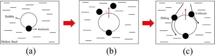
As a result, the mechanism of dissolved gas flotation method includes bubbles nucleating on the surface of inclusions carry the inclusions to slag directly23) and a high adhesion probability of the bubbles to inclusions during the floating process. These two mechanisms working together can effectively remove the inclusions in molten steel, as shown in Fig. 10.
5. Conclusions
A kinetic model was constructed to analyze the bubble growth and floating behavior during the degassing process of molten steel/(N2, H2) system, and its accuracy was verified by water modelling experiments. The following specific conclusions can be made based on the obtained results:
(1) The pretreatment pressure and bubble nucleation depth have great effects on bubble growth and floating behavior, while vacuum treatment pressure and inclusion radius have small effects on it. The floating velocity and growth rate of bubbles increase with the increase of pretreatment pressure or the decrease of nucleation depth.
(2) Gas type has significant effects on bubble growth and floating behavior. The mass transfer coefficient of hydrogen in molten steel is larger than that of nitrogen resulting in a faster growth rate and floating velocity of hydrogen bubbles. A large amount of dispersed fine bubbles can be formed in a short time during the degassing process using hydrogen as refining gas, which can improve the effect of inclusion removal.
(3) The diameters of the bubbles formed via dissolved gas flotation method are 0.2 to 10 mm in most cases during the floating process and the distribution of these fine bubbles is dispersed. These dispersed fine bubbles can remove the inclusions effectively.
Acknowledgements
The authors gratefully acknowledge the financial support of this research by the National Natural Science Foundation of China (Grant No. 51874028).
References
- 1) X. L. Guo, J. B. Yu, X. F. Ren, D. H. Xue, W. D. Xuan, Y. B. Zhong and Z. M. Ren: Ironmaking Steelmaking, 6 (2017), 648.
- 2) L. H. Wang, H.-G. Lee and P. Hayes: ISIJ Int., 36 (1996), 17 .
- 3) X. Zheng, P. C. Hayes and H. G. Lee: ISIJ Int., 37 (1997), 1091.
- 4) S. H. Zhan, J. J. Wang, S. T. Qiu, Z. Q. Xiao and Y. Gan: J. Anhui Univ. Technol., 23 (2006), 367 (in Chinese).
- 5) E. T. Turkdogan: Ironmaking Steelmaking, 31 (2004), 131.
- 6) H. Matsuno, Y. Kikuchi, M. Komatsu, M. Arai, K. Watanabe and H. Nakashima: Iron Steelmaker, 20 (1993), 35.
- 7) X. Q. Bai, D. H. Li, L. Zhang and J. C. He: Acta Metall. Sin., 38 (2002), 483.
- 8) K. W. Li, J. H. Liu, J. B. Zhou, Y. L. Ji, Z. B. Han and Y. He: Chin. J. Eng., 37 (2015), 1124.
- 9) H. Matsuno, Y. Kikuchi, M. Arai, K. Yamada and T. Ishii: Tetsu-to-Hagané, 85 (1999), 514 (in Japanese).
- 10) Y. P. Bao, J. H. Liu and B. M. Xu: Int. J. Miner. Metall. Mater., 10 (2003), 20.
- 11) F. P. Tang, Z. Li, X. F. Wang, B. W. Chen and P. Fei: Int. J. Miner. Metall. Mater., 18 (2011), 144.
- 12) L. H. Wang, H.-G. Lee and P. Hayes: ISIJ Int., 36 (1996), 7.
- 13) D. Mazumdar and R. I. L. Guthrie: ISIJ Int., 35 (1995), 1.
- 14) Q. Y. Zhang, L. T. Wang and Z. R. Xu: ISIJ Int., 46 (2006), 1177.
- 15) P. Wei, K. I. Uemura and S. Koyama: Tetsu-to-Hagané, 78 (1992), 1361 (in Japanese).
- 16) A. V. Nguyen, H. J. Schulze and J. Ralston: Int. J. Miner. Process., 51 (1997), 183.
- 17) L. Zhang, J. Aoki and B. G. Thomas: Metall. Mater. Trans. B, 37 (2006), 361.
- 18) H. L. Yang, P. He and Y. C. Zhai: ISIJ Int., 54 (2014), 578.
- 19) J. Zhang, J. H. Liu, S. J. Yu, D. X. Dong, G. L. Wang and S. Q. Li: Metals, 8 (2018), 560.
- 20) S. H. Huang and Z. Li: Eng. J. Wuhan Univ., 35 (2002), 13 (in Chinese).
- 21) S. H. Huang and L. J. Cheng: Shuili Xuebao/J. Hydraul. Eng., 7 (1996), 54.
- 22) H. D. Tian, L. A. Jin, W. Chi, Y. Pang, Y. D. Han and Y. Wang: Chin. J. Theor. Appl. Mech., 43 (2011), 680 (in Chinese).
- 23) K. W. Li, J. H. Liu, J. Zhang and S. B. Shen: Metall. Mater. Trans. B, 48 (2017), 2136.
- 24) M. H. Chen, D. Z. Cong and T. N. Fang: Principles of Chemical Engineering, Chemical Industry Press, Beijing, (2000), 56 (in Chinese).
- 25) G. Laslaz and P. Laty: AFS Trans., 99, (1991), 83.
- 26) X. H. Huang: Principal of Iron and Steel Metallurgy, Metallurgical Industry Press, Beijing, (2002), 78 (in Chinese).
- 27) J. Szekely and G. P. Martins: Chem. Eng. Sci., 26 (1971), 147.
- 28) S. X. Zhou, J. Fu and P. Wang: Chin. J. Eng., 6 (1998), 522.
- 29) International Iron and Steel Institute: IISI Study on Clean Steel, Metallurgical Industry Press, Beijing, (2006), 125.