Abstract
Utilization of biomass char, which is regarded as a carbon neutral fuel, has been discussed to decrease in the carbon dioxide emission from the ironmaking processes. However, carbonization usually leads to a significant carbon loss. In this study, the direct use of uncarbonized biomass for the reduction of iron ore was attempted. First, reduction behavior of the iron ore-uncarbonized biomass composite was examined to understand the reduction mechanism at elevated temperature. Second, reduction tests using a rotary kiln type furnace were conducted to propose a new reduction process of iron ores. In this process, stainless steel balls are utilized to supply heat and pulverize carbonized biomass and reduced iron ore through collisions with balls. The effect of process parameters on the reduction behavior was examined.
Metallic iron formed in the composite of iron ore and uncarbonized biomass by heating over 800°C under inert gas atmosphere. Heating these materials in a rotary kiln type furnace over 950°C also led to metallic iron formation. Increasing in the treatment temperature and time increasd reduction degree. The results showed a possibility that the HSM (heat storage material) balls accelerate the reduction of iron ore, and the carbonization and pulverization of biomass.
1. Introduction
In the ironmaking process, an innovative technology to drastically decrease carbon dioxide emissions has been strongly required. However, it is not easy since the ironmaking process requires a large amount of energy in principle and the current blast furnace process is already highly efficient. Utilizations of green hydrogen and carbon-neutral carbonaceous materials will be the ways to decrease the carbon dioxide emission, although it will be difficult to use sufficient amount of green hydrogen in the immediate future.
There are also some issues on the utilization of biomass such as their low energy density and inefficient collection systems. In Brazil, a part of molten iron is produced by small size blast furnaces using biomass char.1) Further, a trial was made that woody biomass was utilized in the coke making process and obtained char was injected the blast furnace through tuyeres.3,4) The heat of 120–148 J/g5) is required for the carbonization depending on the type of biomass, its water content and carbonization condition. Some of heats will not be necessary if biomass can directly use for the reduction of iron ores.
The authors have proposed a rapid carbonized process using a rotary kiln-type furnace applying heat storage materials balls, namely HSM-PC balls, which promote heat transfer and pulverization of produced char.6) In this study, a trial was made to apply of this process to the production of direct reduced iron (DRI) by charging both biomass and iron ore. Rotary kilns have been applied mainly for the recycling of iron-bearing ducts formed from steel industry.7) The originality of this study is the utilization of heat storage materials for energy supply to reduction process and uncarbonized biomass for reducing agent to a rotary kiln. It is expected that this suggested process does not emit carbon dioxide originated from fossil fuel. There is a possibility that DRI can be produced rapidly.
The reduction of iron oxide basically proceeds stepwise from hematite to magnetite, to wustite and to metallic iron by the following reactions:
|
3F
e
2
O
3(s)
+C
O
(g)
→2F
e
3
O
4(s)
+C
O
2(g)
| (1) |
|
F
e
3
O
4(s)
+3C
O
(g)
→3Fe
O
(s)
+3C
O
2(g)
| (2) |
|
Fe
O
(s)
+C
O
(g)
→F
e
(s)
+C
O
2(g)
| (3) |
The values of equilibrium oxygen partial pressures for
Eqs. (1) and
(3) are highest and lowest, respectively. For example, metallic iron can form at 1000°C under the condition of oxygen partial pressure less than 10
−10 Pa, which is corresponding to the partial pressure ratio, P
CO/(P
CO + P
CO2), larger than 0.7.
Carbonization of biomass proceeds with generation of H2O and CO2 gases originated from combined water, and carbonyl, hydroxyl groups,8) and so on, resulting in an increase in oxygen partial pressure. It is a reason why uncarbonized biomass has not directly utilized to the ironmaking process. However, the reactions of Eqs. (1) and (2) do not require such low oxygen partial pressure. The values of equilibrium oxygen partial pressures of these reactions at 700°C are approximately 10−7 and 10−16 Pa, respectively. These values are corresponding to PCO/(PCO + PCO2) of 4 × 10⁻⁵ and 0.4, respectively. During carbonization, CO, H2, and hydrocarbon gases generate together with H2O and CO2. It means that uncarbonized biomass has a certain reduction potential. Reduction of wustite to metallic iron will be possible after carbonation of biomass is completed since biomass char itself shows high reduction potential.
Ueki et al. reported on the metallic iron formation observed for the composites prepared using ceder powder and hematite reagent at 1000–1300°C.9) Wei et al. examined the reduction experiment of the composite using pine sawdust at 800–1250°C.10) Although both studies employed isothermal reduction conditions, experiment under an elevated temperature is more suitable since carbothermic reduction of the composite is an endothermic reaction and initial raw materials are at room temperature.
In this study, therefore, an elevated temperature condition was applied to the reduction experiment of the composite. Japanese cypress and iron ore were used for the preparation of the composite samples. The reduction behaviors of the composite, especially the formation temperature of metallic iron was discussed based on the experimental results. Furthermore, the reduction experiment of the iron ore by Japanese cypress was conducted using a laboratory scale rotary kiln, and significant process parameters was examined, which affect the reduction behaviors, such as temperature, retention time, and the number of HSM-PC balls.
2. Reduction Reaction of Composite
2.1. Experimental Procedure
Australian iron ore (T. Fe: 57.2 mass%, SiO2: 5.5 mass%, Al2O3: 2.5 mass%, LOI: 10.1 mass%) with particle size less than 250 μm was used. Japanese cypress which is one of typical conifer in Japan was pulverized by a ball mill under the cooling condition using liquid nitrogen, and sieved to be less than 250 μm in particle size. Ultimate and proximate analyses data of Japanese cypress are listed in Table 1. The amounts of fixed carbon and volatile matter of un-carbonized biomass are lower and higher than those reported by Ueki et al.,9) respectively. The amount of ash is less than 1%, which is significantly lower than that of coal.11)
Table 1. Ultimate and proximate analyses of biomass used in this study (mass%).
| Cypress | Ultimate analysis | Proximate analysis |
|---|
| C | H | N | O | T-S | F.C | V.M. | Ash | Water |
|---|
| Un-carbonated | 46.85 | 6.27 | 0.20 | 46.34 | 0.08 | 12.48 | 87.26 | 0.26 | 10.78 |
T-S: total sulf
Un-carbonized biomass and iron ore were carefully mixed not to reduce their particle sizes. The molar ratio of total carbon contained in the uncarbonized biomass to oxygen in the iron oxide, namely total-C/O, of the powder mixture was changed from 0.5 to 1.52. The mixture was press-shaped under a pressure of 9.8 × 10⁷ Pa using a die, and a composite sample with a diameter of 10 mm was prepared. Al2O3 powder with the average particle size was 1 μm was used as an inert spacer in order to individually observe the gasification behavior of un-carbonized biomass and the decomposition of combined water in iron ore, respectively. Al2O3/un-carbonized biomass and Al2O3/iron ore composite were prepared to estimate reduction degree.
The experimental apparatus12) used for the reduction of the composite is shown in Fig. 1. The composite sample was set in a holder made of alumina and it was placed in a silica chamber. The air in the chamber was vacuumed, and then when the value of differential pressure gauge indicated −0.1 MPa, Ar-5%N2 gas was flowed into the chamber at the rate of 8.3 × 10⁻³ L/s. When oxygen concentration in the outlet gas of the furnace was below 10 ppm, the composite sample started to be heated up to 1200°C at the heating rate of 0.167°C/s, and then it was cooled by turning off the power of the infrared furnace. Gas chromatography was used to measure periodically (90 s) the concentration of CO, CO2, H2, H2O, O2, N2, CH4, C2H4, and C2H6. The concentration of N2 gas was used to estimate the change in the total gas volume during heating. Reduction degree of the composite sample, R.D. is defined by Eq. (4).
|
R.D.=
M
CO
+2
M
CO
2
+
M
H
2
O
-
M
LOI
-
M
vol
M
total O
| (4) |
,
MCO2, and
MH2O are the molar amounts of oxygen in the CO, CO
2, and H
2O gases released from the composite, respectively.
MLOI and
Mvol are the molar amount of oxygen originated from combined water in ore and reagent and that of volatile matter in biomass, respectively. These values were obtained to analyze gases generated from the ore-alumina and the biomass-alumina composites, respectively.
Mtotal O is the total molar amount of oxygen in the iron oxide sample.
After the reduction experiment, the compounds existed in the composite samples were identified by XRD (RIGAKU SmartLab. 40 kV, 30 mA, Fe Kα (0.19373 nm)). Further, carbon content remained in the composite sample was measured by the infrared absorption method using CS884 combustion analyzer (LECO).
2.2. Results and Discussion
Figure 2 shows the changes in gas generation rates from the composite (total-C/O = 1.0) of iron ore and un-carbonated biomass during heating. Significant gas generation was observed at over 300°C. It is caused by decomposition of biomass and combined water in iron ore. The generation rate of CO gas rapidly increases above 720°C due to progress of gasification reaction of carbon. Figure 3 shows the change in reduction degree of the composite (total-C/O = 1.0) using uncarbonized biomass. Reduction degree rapidly increases at approximately 720°C, and reduction reaction almost finishes at approximately 1000°C. It seems to correspond to the gas generation behaviors shown in Fig. 2. At this temperature, CO gas can generate by the gasification reaction of carbonized biomass with H2O and CO2.13) The reason is discussed at next paragraph.


In order to discuss the reduction behaviors of the composite, XRD profiles of the composite samples heated up to 800°C, 1000°C, and 1200°C are shown in Fig. 4. Figure 5 shows the change in the PCO/(PCO + PCO2) with temperature on the Baur–Glässner diagram. At 800°C, not only hematite and magnetite but also wustite and metallic iron were identified in the XRD profile. On the other hand, the value of PCO/(PCO + PCO2) (CO gas ratio) is higher than that of the equilibrium line of wustite and metallic iron. Metallic iron was only observed at the outside of the composite. Furthermore, the decomposition of biomass is endothermic reaction. These indicate that the reduction reaction proceeds topochemically in the composite. Graphite phase was also detected, which originated to carbon in biomass as shown in Fig. 4. It can be concluded that heating the composite sample above 800°C enable to form metallic iron. At 1000°C, major phase is metallic iron, and small amounts of wusitite and Fe2SiO4 are found. Fe2SiO4 may form by the reaction of wustite and SiO2 contained in the iron ore. Less amount of Fe3C and trace amount of graphite are also detected. At 1200°C, graphite was not detected showing that solid carbon was consumed through its gasification reaction. This is consistent with the results that reduction degree did not change above 1000°C as shown in Fig. 3. On the other hand, small amount of cementite is observed at 1000°C and 1200°C. From Fig. 5, CO gas ratio is higher than that calculated from the equilibrium of Fe/FeO. It has a potential that CO gas carburization proceeds up to approximately 0.2 mass%C. During cooling, cementite forms while carbon solutes in the austenite phase at high temperature such as 1200°C.

Figure 6 shows the effect of total-C/O on reduction degree of the composite sample using uncarbonated biomass and the amount of remained carbon concentration in the composite heated up to 1200°C. Reduction degree of the composite increases with an increase in total-C/O. The concentration of remained carbon is almost zero below total-C/O = 1.27 indicating that all carbon was consumed during heating. In the case of total-C/O = 1.52, reduction degree and the amount of remained carbon are 92% and 2.4%, respectively. It indicates that reduction degree almost finishes, and a certain amount of carbon remains, which can be utilized as carburization agent.14)
3. Reduction Experiment Using Laboratory Scale Rotary Kiln
3.1. Experimental Procedure
Japanese cypress cube and Australian iron ore with 10 mm in side length and 2–4.76 mm in particle size, respectively were used. Figure 7 shows the illustration of a laboratory scale rotary kiln used for reduction experiment of iron ore. The inside diameter of the reaction tube made of Inconel 601 is 83.1 mm. Length of the tube is 670 mm, which consists of heating and cooling sections of 155 mm and 370 mm in length, respectively. These sections are divided by stainless plate with the diameter of 81.8 mm or 82.5 mm having a hole of 7 mm in diameter at the center part, which is called as the filter. Two types of plates with the diameter of 81.8 mm and 82.5 mm were used. Two blades are attached inside the heating section to promote the mixing of samples and HSM-PC balls. The apparatus is tilted 1° from horizontal direction to cooling section.

A certain number, 0–200, of HSM-PC balls made of SUS304 with the diameter of 9.5 mm were charged to the reactor. Then, it was heated up to the target temperature, 950–1050°C, under the flow of nitrogen gas at 8.33 × 10⁻³ NL/s. The reaction tube was rotated with the speed of 10 rpm for 0.9 ks. After that, 50 g of iron ore and 25 g of Japanese cypress of 50 pieces were charged into the tube from the left side of the heating section. First, the sample was set into three special sample holders. The ball valve at the left side of the furnace was open. Then, the long stainless bar was pushed into the furnace, and the sample of iron ore and biomass moved into the furnace. After pushing, the bar was pulled back to the initial point, and the ball valve was closed. By this operation, inert atmosphere could be kept. This operation was carried out three times to insert all samples. The charging molar ratio of total carbon in biomass to oxygen in iron oxide was 1.27. After a certain period of time, the rotation and heating operation was stopped, and the reaction tube was cooled to below 100°C. Then, the sample was recovered from both of the heating and cooling sections.
The obtained sample was weighed before and after separation of carbon and iron materials which were separated to metal and oxide using ethanol.14) The components of the sample were identified by XRD. Total amount of iron and Fe2+ were analyzed by neutralization titration (JIS K1310) to calculate metallization degree. Oxygen content in the sample was measured by the infrared absorption method to calculate reduction degree of iron ore.
3.2. Results and Discussion
Figure 8 shows the effect of number of balls on the mass balance of carbonaceous materials added with iron ore heated at 950°C for 3.6 ks. The filter with the diameter of 81.8 mm was used. Charged biomass was decomposed to volatile matter and char. The latter was obtained from both heating and cooling sections. The weight ratio of volatile matter was calculated from the Eq. (5).
|
W
vol
=100-(
W
Cooling
+
W
Heating
)
| (5) |
Here, W
vol is the weight ratio of volatile matter to biomass charged into the reaction tube. W
Cooling and W
Heating are those of char obtained from cooling and heating sections. When the sample was collected from the reaction tube, the recovery loss was up to approximately 0.5 g, which was ignored to calculate the sample weight. The ratio of char remained at inside of heating section, W
Heating decreases with increasing number of balls. When the number of balls is 200, W
Heating is very few. On the other hand, the ratio of char obtained from cooling section, W
Cooling increases. Biomass and its carbonized char are easy to be pulverized compared to iron ore. After pulverizing, biomass char passes through the gap between the filter and the reaction tube, which is 0.35 mm, and escapes into cooling section.
Figure 9 shows the effect of heat treatment time on the mass balance of carbonaceous materials heated at 950°C using 0 and 100 number of HSM-PC balls. In the case without balls, the weight ratio of remained char in heating section, WHeating decreases with time. It means that the carbonization reaction of biomass proceeds. In case with 100 balls, WHeating is less than 10% when the treatment time is 0.9 ks. The reason is that biomass was pulverized by balls and rapidly carbonized.6) Furthermore, there is a trend that the amount of char in cooling section, WCooling increases with passing the treatment time. This may affect the reduction of iron ore.
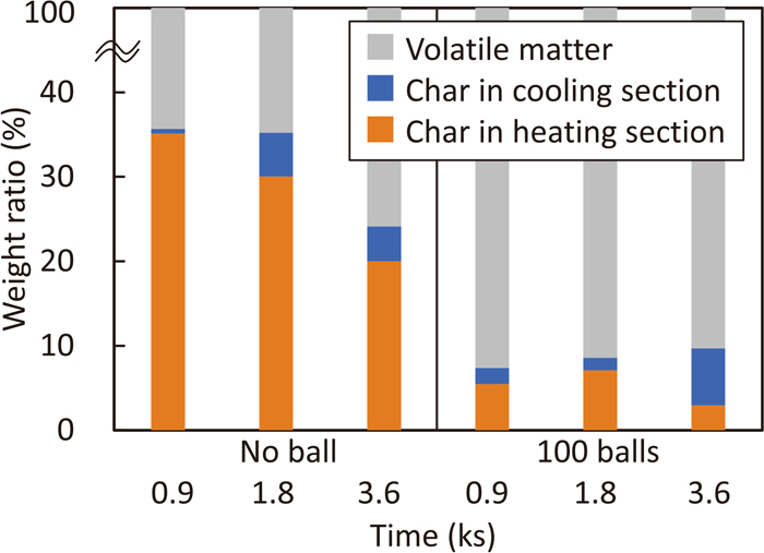
Figure 10 shows XRD profiles of sample recovered from heating section heated with 100 number of balls at 950°C. For 0.9 ks. In this case, major compound is wustite. Minor compounds, i.e., fayalite (Fe2SiO4), graphite and metallic iron are also detected. For 1.8 ks, the peak intensity of metallic iron increases and that of wustite decreases. It means that the reduction reaction of wustite proceeds and the amount of metallic iron increases. The peak intensity of metallic iron for 3.6 ks is similar to that for 1.8 ks while reduction degree should be higher. However, it can be concluded that the amount of formed metallic iron increases as the following reason. The peak intensity of XRD profile affects the occupancy of sample surface. The peak decreases when the particle size increase because the surface occupancy decreases.16) The particle size of metallic iron increases by the progress of reduction, especially at late stage of reduction. It is difficult to decrease the particle size of metallic iron by pulverization using a mortar at room temperature when the sample for XRD was prepared. Furthermore, the peak intensity of graphite increases rapidly at 3.6 ks showing that carbonization of biomass proceeded. Figure 11 shows XRD profiles of sample recovered from heating section heated with 0 and 200 number of balls at 950°C for 3.6 ks. Metallic iron is detected in both samples although the increase in number of balls led to decreasing peak intensity of metallic iron. There is a possibility of decrease in the ratio of metallic iron with increasing the number of balls. It will be discussed at next paragraph.


Figure 12 shows the effect of number of HSM-PC balls on the metallization degree of sample obtained from heating and cooling sections at 950°C for 3.6 ks. Metallization degree of samples obtained in both heating and cooling sections decreased with increasing number of balls. Small amount of iron bearing materials was obtained from the cooling section. The metallization degree of this sample is lower than that obtained from heating section. In this system, the inserted biomass is decomposed into volatile matter and char in the kiln, and iron ore is reduced by the volatile matter and the reducing gas generated by the gasification reaction of char, simultaneously. When the HSM-PC balls exists in the kiln, the decomposition reaction of biomass is accelerated by the rapid heating due to direct contact with the balls and the pulverization of biomass and iron ore by the balls also proceeds. From these obtained results, however, the contribution of volatile matter for the reduction of iron ore was low because HSM-PC balls pulverize biomass and its char. Furthermore, pulverized iron ore and its reduction product moves to cooling section.

To suppress the escape of sample to the cooling section, the diameter of the filter increases up to 82.5 mm. Figure 13 shows the effect of heat treatment temperature on the reduction degree of iron ore remained in the heating section when using this filter. In this case, no ball was used and the treatment time was set at 3.6 ks. Reduction degree increases with increasing the treatment temperature. Microstructures of samples obtained from the heating section at 950°C and 1050°C are shown in Fig. 14. Metallic iron and wustite phases are observed in both samples. The amount of metallic iron increases with increasing temperature. This result is consistent with the results of reduction degree.
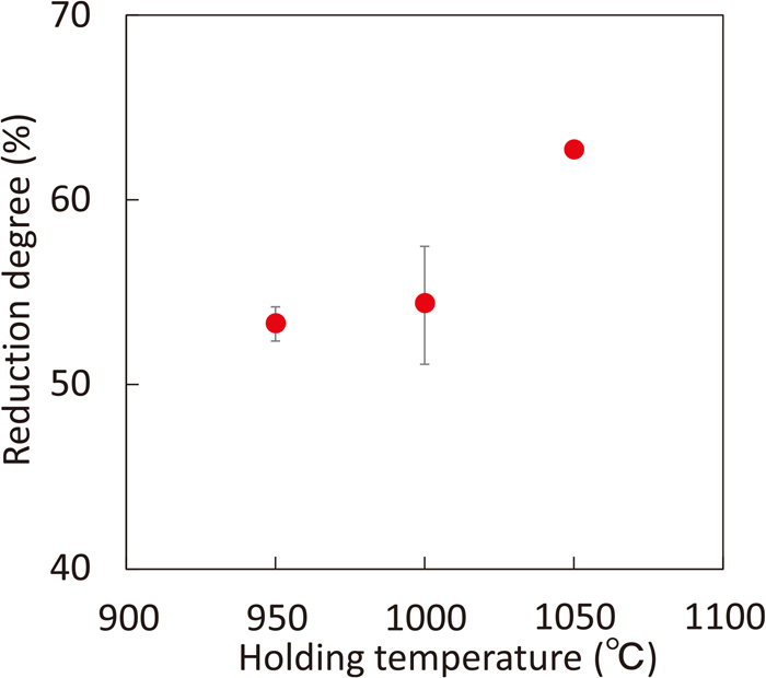
Figure 15 shows the effect of treatment time on reduction degree and char recovery ratio of sample obtained from the heating section at 1000°C without balls. Reduction degree of sample increases with an increase in treatment time. On the contrary, char recovery ratio decreases. It indicates that char reacts to reduce iron ore in the heating section. Microstructures of samples obtained from heating section in the furnace at 1000°C without balls for 1.8 and 7.2 ks are shown in Fig. 16. Metallic iron sparsely forms near the surface of the iron ore particle at 1.8 ks. On the other hand, dense metallic iron layer forms at 7.2 ks. This behavior suggests the possibility to suppress the reduction reaction because metallic layer prevents to contact iron oxide with reducing gas.


Finally, the effect of HSM-PC balls on the reduction was evaluated. Figure 17 shows the effect of number of balls on reduction degree of sample obtained from heating section at 1000°C for 7.2 ks. Reduction degree slightly decreases with increasing number of balls while metallization degree drastically decreases when using the filter of 81.8 mm in diameter as shown in Fig. 12. The reason of the difference is that the pulverized carbonaceous materials and iron ore did not move to cooling section. Figure 18 shows the particle size distribution of reduced iron ore obtained from heating section with 0 and 200 number of balls. The ratio of particle size distribution less than 0.5 mm drastically increases with increasing number of balls. The reason why reduction degree did not increase by increasing number of balls may be explained as follows: HSM-PC balls pulverized not only iron ore but also biomass char. They also accelerate the carbonization and therefore generation of volatile matter occurred in a short period of time. As a result, volatile matter did not effectively utilize to the reduction reaction. In this study, biomass cube with the size of 10 mm was used. In an actual process, the size of biomass will be much larger than laboratory scale. In such a case, the decrease in reduction degree by using HSM-PC balls will be restrictive because carbonization time will be much longer.

4. Conclusions
In this study, a new ironmaking process which can drastically decrease carbon dioxide emission caused by fossil fuel was suggested by direct utilization of uncarbonized biomass as a reducing agent for iron ore. This process also uses HSM-PC balls not only to pulverize iron ore and biomass but also to accelerate the carbonization of biomass. The reduction mechanism of composite using uncarbonized biomass and iron ore and the effect of major process parameters of the reduction process of iron ore by biomass using a laboratory scale rotary kiln furnace were examined. The following results were obtained:
• By heating at an elevated temperature of the composite prepared using Japanese cypress and iron ore, whose mixing ratio (Total-carbon/oxygen in iron ore in molar) is 1.0, metallic iron forms at approximately 800°C and reduction almost finished at about 1000°C.
• Increase in the mixing ratio of Japanese cypress to iron ore leads to an increase in reduction degree. When total-C/O is 1.52, reduction reactions almost complete and carbonized char remains in the reduced composite.
• Using a laboratory scale rotary kiln heated above 950°C, the formation of metallic iron was confirmed through reduction of iron ore by Japanese cypress. In this case, reduction degree increases with the treatment temperature.
• The utilization of HSM-PC balls accelerates not only the pulverization of iron ore and biomass, but also the carbonization of the biomass. This is not suitable for the reduction of iron ore because it shortens time to react with volatile matter generated from biomass. It is required to control the carbonization rate by optimizing the size of biomass.
Acknowledgment
This study was supported partly by Steel Foundation for Environmental Protection Technology and a research promotion grant from the Iron and Steel Institute of Japan. The authors greatly appreciate the experimental work of Mr. K. Inujima, and Mr. W. Endo who were members of our laboratory of Tohoku University.
Nomenclature
R.D.: reduction degree (%)
Mi: molar amounts of oxygen in i (i = CO, CO2, H2O gases) released from the composite (mol)
MLOI: molar amount of oxygen originated from combined water in ore (mol)
Mvol: molar amount of oxygen originated from volatile matter in biomass (mol)
Mtotal O: total molar amount of oxygen in iron oxide (mol)
total-C/O: molar ratio of total carbon contained in the uncarbonized biomass to oxygen in iron oxide
HSM-PC balls: heat storage materials balls for a rotary kiln-type furnace with the function of pulverization of raw materials
Wvol: weight ratio of volatile matter to biomass charged into the reaction tube (%)
WCooling: weight ratio of char obtained from cooling section to biomass charged into the reaction tube (%)
WHeating: weight ratio of remained char obtained from heating section to biomass charged into the reaction tube (%)
References
- 1) R. Taniguchi and Y. Serizawa: Tetsu-to-Hagané, 68 (1982), 2086 (in Japanese). https://doi.org/10.2355/tetsutohagane1955.68.15_2086
- 2) M. Ikemori, Y. Nunome, Y. Ueki, R. Yoshiie, I. Naruse, Y. Nishibata and S. Aizawa: Proc. Conf. Coal Sci., 49 (2012), 58.
- 3) S. Ueda, R. Inoue and T. Ariyama: Tetsu-to-Hagané, 94 (2008), 468 (in Japanese). https://doi.org/10.2355/tetsutohagane.94.468
- 4) H. Tsuruta, M. Asanuma, A. Fujibayashi and A. Murao: Proc. Conf. Biomass Sci., 8 (2012), 10.
- 5) M. Van de Velden, J. Baeyens, A. Brems, B. Janssens and R. Dewil: Renew. Energy, 35 (2010), 232. https://doi.org/10.1016/j.renene.2009.04.019
- 6) D. Maruoka, T. Nakamura, T. Murakami and E. Kasai: Tetsu-to-Hagané, 102 (2016), 730 (in Japanese). https://doi.org/10.2355/tetsutohagane.TETSU-2016-025
- 7) X. G. Xiao, M. Kuwabara and I. Muchi: Tetsu-to-Hagané, 72 (1986), 380 (in Japanese). https://doi.org/10.2355/tetsutohagane1955.72.3_380
- 8) Y. Lu, Y. C. Lu, H. Q. Hu, F. J. Xie, X. Y. Wei and X. Fan: J. Spectrosc., 2017 (2017), 8951658. https://doi.org/10.1155/2017/8951658
- 9) Y. Ueki, R. Yoshiie, I. Naruse, K. Ohno, T. Maeda, K. Nishioka and M. Shimizu: Fuel, 104 (2013), 58. https://doi.org/10.1016/j.fuel.2010.09.019
- 10) R. Wei, D. Cang, Y. Bai, D. Huang and X. Liu: Ironmaking Steelmaking, 43 (2016), 144. https://doi.org/10.1179/1743281215Y.0000000061
- 11) T. Y. Huang, D. Maruoka, T. Murakami and E. Kasai: ISIJ Int., 59 (2019), 1982. https://doi.org/10.2355/isijinternational.ISIJINT-2019-178
- 12) T. Murakami, H. Shinomiya, D. Maruoka and E. Kasai: ISIJ Int., 59 (2019), 1011. https://doi.org/10.2355/isijinternational.ISIJINT-2018-725
- 13) R. Higashi, K. Owaki, D. Maruoka, T. Murakami and E. Kasai: ISIJ Int., 61 (2021), 1808. https://doi.org/10.2355/isijinternational.ISIJINT-2020-746
- 14) T. Murakami, M. Ohno, K. Suzuki, K. Owaki and E. Kasai: ISIJ Int., 57 (2017), 1928. https://doi.org/10.2355/isijinternational.ISIJINT-2017-249
- 15) D. Mohan, C. U. Pittman, Jr. and P. H. Steele: Energy Fuels, 20 (2006), 848. https://doi.org/10.1021/ef0502397
- 16) T. Harano, Y. Nemoto, R. Murao and M. Kimura: ISIJ Int., 60 (2020), 2851. https://doi.org/10.2355/isijinternational.ISIJINT-2020-188


