Abstract
From the aspect of crack/void initiation and growth characteristics, the effects of pre-strain on the hydrogen embrittlement resistance of a transformation-induced plasticity-aided bainitic ferrite steel were examined. The hydrogen uptake in the specimens without pre-strain caused degradation of crack growth resistance, but the crack initiation probability did not change significantly. It is noteworthy that the degree of degradation was independent of the hydrogen content in the present hydrogen charging condition. Pre-straining to 3% and 6% improved the crack growth resistance of the hydrogen-charged specimens because of a reduction in the probability of austenite presence at the crack tip. Furthermore, a high level of pre-strain provided high hydrogen concentration and resulted in strain-age-hardening, which caused an acceleration of quasi-cleavage fracture, an increase in yield strength, and a stress/strain concentration associated with Lüders deformation. These factors diminished the crack initiation resistance and crack growth resistance.
1. Introduction
The automotive industry requires steel with high specific strength to improve the fuel cost performance. Transformation-induced plasticity (TRIP) steels are candidate materials because of their excellent balance between strength and ductility, which originates from the retained austenite that transforms into martensite upon plastic deformation.1,2,3) In particular, TRIP-aided bainitic ferrite (TBF) steels, which have a bainitic ferrite matrix,4,5,6) display superior plastic formability (e.g., high hole-expanding ratio).7) Therefore, the family of TBF steels has already been used for automobile applications, such as doors and frames.
A recent concern with respect to TBF steels is the susceptibility to hydrogen embrittlement, similar to other high-strength metals, such as martensitic and dual phase steels.8) According to a previous study,9) the hydrogen embrittlement of TBF steels occurs via transgranular cracking in fresh martensite formed from retained austenite. The cause of cracking is the supersaturation of hydrogen in the fresh martensite owing to the difference in hydrogen solubility between the face-centered cubic and body-centered cubic structures.10,11) Therefore, a reduction in the retained austenite fraction before mechanical testing can decrease the hydrogen embrittlement susceptibility. Specifically, pre-strain, which induces martensitic transformation before the test, can suppress the occurrence of hydrogen embrittlement.9,12,13)
However, it is also noteworthy that hydrogen embrittlement in TBF steel occurred even after large pre-straining when the diffusible hydrogen content increased.9,12) The hydrogen content of the pre-strained specimen was higher than that without pre-strain even under identical hydrogen-charging conditions.9) In the pre-strained steel, the increase in dislocation density results in trapping more hydrogen and increasing the hydrogen content,14,15) which can assist transgranular cracking. Moreover, when a large plastic strain was provided, the retained austenite almost disappeared.9) Therefore, it is considered that the crack initiation site with high pre-strain and hydrogen content is different from that with low pre-strain. Moreover, the pre-strain and subsequent deformation cause strain aging, which increases the flow stress. The increase in resistance to plastic deformation also has a disadvantageous effect on hydrogen embrittlement resistance.9)
The specific relationship between strength, hydrogen content, and pre-strain in TBF steel is summarized in Fig. 1. The fracture strength is highly dependent on the pre-strain and hydrogen content, but there are many uncertainties regarding the effects of the hydrogen content, retained austenite fraction, and strain aging on the micro-crack and void evolution behaviors. This study presents a variety of hydrogen-assisted microstructural cracking behaviors of TBF steels with different hydrogen contents and pre-strains.
2. Experimental Procedure
2.1. Material
The chemical composition of the cold rolled steel used in this study is shown in Table 1. The material was austenitized at 915°C for 1200 s, followed by austempering at 425°C for 500 s in a salt bath, yielding a multi-phase microstructure consisting of a bainitic ferrite matrix with interlath-retained austenite, hereafter referred to as TBF steel. To understand the basic microstructure of the material used in this study, we conducted microstructure observations. Part of the material was sliced and polished sequentially with 320-, 600-, and 1200-grade emery sheets, and mirror polished with colloidal silica. The polished material was then etched, and the etched surface was observed with a scanning electron microscope (SEM; Hitachi TM4000) operated at 15 kV. The observed microstructure is shown in Fig. 2. Blocky austenite and bainitic ferrite lath are seen in the SEM micrograph. In addition, presence of interlath austenite films in the same material has been reported in a previous paper.12)
Table 1. Chemical composition of the steel sample (mass%).
| C | Si | Mn | Al | Nb | Mo | O | N |
|---|
| 0.4 | 0.49 | 1.51 | 1.02 | 0.05 | 0.2 | 0.0015 | 0.0019 |
Figure 3 shows the tensile specimen geometry used in the tensile test. The tensile specimen was fabricated by laser cut and mechanically polished. The tensile test was carried out on a tensile testing machine (AGS – X Shimadzu) with a strain rate of 2.78 × 10⁻⁴ s−1 at room temperature (23°C).
Tensile tests were conducted for specimens with different pre-conditions—uncharged, pre-strained, and hydrogen-charged. The pre-condition and mechanical properties of tensile tested samples are listed in Table 2. The specimens were electrochemically charged with hydrogen for 48 h at room temperature and respective current densities in a 3% NaCl aqueous solution containing 5 g L−1 ammonium thiocyanate (NH4SCN). Tensile test was conducted immediately after hydrogen charging to avoid any hydrogen evolution.
Table 2. Test conditions and obtained tensile properties. Specimen numbers correspond to the numbers in
Fig. 1.
| Specimen No. | Pre-strain | Current density
(A m−2) | Elongation +
pre-strain | True fracture strength (MPa) |
|---|
| 1 | 0% | No charge | 29% | 994 |
| 2 | 0% | 1 | 10% | 986 |
| 3 | 0% | 10 | 11% | 981 |
| 4 | 3% | 1 | 21% | 1020 |
| 5 | 6% | 1 | 24% | 1004 |
| 6 | 15% | 10 | 16% | 1018 |
To analyze the effect of the Lüders band on damage evolution, two additional specimens were prepared. One specimen was deformed to 6% strain without hydrogen charging, charged with hydrogen at 1 A m−2 for 48 h, then deformed from 6% to 10% strain. The other specimen was hydrogen pre-charged for 48 h, then deformed to 10% strain. Microstructure evolution and the location of the Lüders front of the two specimens were comparatively analyzed using optical microscopy.
To avoid hydrogen desorption, part of the fractured specimen was immediately preserved in a refrigerator and later used for conducting thermal desorption spectroscopy (TDS) analysis to measure the hydrogen content. The remainder was used for conducting microstructural analysis. A quadrupole mass spectrometer was used to measure the hydrogen content in the specimen. The sample was heated from room temperature to 800°C at a heating rate of 100°C h−1.
2.3. Damage Characterization
Microstructural analysis was performed using optical microscopy and SEM to quantify the damage to the specimen at each strain level, which was prepared by slicing in the transverse plane of the fractured specimen and polishing with emery papers and colloidal silica to achieve a mirror surface. The microstructure and damage were observed at various locations with difference local reductions in thickness of the fractured specimen. The damage observed under SEM was quantified as the number density of damage, defined as the total number of damages observed in the unit area of observation.16) This was plotted against the engineering strain obtained from the local reduction in thickness.17) Since the plastic strain near the fracture surface was significantly higher than the macroscopic elongation obtained by uniaxial tensile testing, engineering strains obtained from local reductions in thickness in the final damage evolution stage were larger than the total elongation. In the present analysis, damage is defined as a crack or void with an area greater than 0.76 μm2.
3. Results and Discussion
3.1. Effect of the Hydrogen Content
Figure 4 shows the TDS profiles and diffusible hydrogen content of the specimens. Diffusible hydrogen content increased as current density and pre-strain increased. As reported previously,9) the effect of diffusible hydrogen content was dependent on pre-strain. To isolate the hydrogen content effect, we initially present the stress–strain response and damage evolution with varying hydrogen concentrations and no pre-strain.

Figure 5 shows the engineering stress–strain curves and number density of damage at each level of strain with different hydrogen charging conditions and no pre-strain. Hereafter, the curves with and without the circle marks show number density of damage and stress–strain relationship, respectively. The macroscopic deformation behavior before failure did not change with the hydrogen uptake, and only elongation was reduced. In addition, the degradation of elongation did not change significantly with the change in hydrogen content, and the number density of damage did not change with hydrogen charging, even at 10 A m−2. The damage shape of the uncharged specimen was ellipsoidal (Fig. 6(a)), which is typically initiated from a matrix–inclusion interface. In fact, the damage shape and distribution near the fracture surfaces of the hydrogen-charged specimens were similar to those of the uncharged specimen, irrespective of the current density (Figs. 6(a) and 6(b)). Sharp cracks were rarely observed in the hydrogen-charged specimens, as displayed in the insets of Figs. 6(a) and 6(b). That is, when a sharp crack grew to a critical size in the hydrogen-charged specimen, it did not stop growing until failure. Therefore, we could not observe sharp and well-grown cracks in the hydrogen-charged specimens. The deterioration in crack growth resistance caused by hydrogen reduced the elongation, but its effect did not change with increasing hydrogen content. As discussed in previous studies,9,12) when the pre-strain was not given, the primary microstructural factor was the fraction of retained austenite. This is because supersaturated hydrogen in fresh body-centered-cubic martensite that was transformed from retained austenite during deformation assists cracking.11,18,19) Here, we must note that a half of the retained austenite in the present TBF steel remained even after plastic deformation of over 20% strain.12) Therefore, the effect of supersaturated hydrogen on crack initiation is minor in the early deformation stage, and it plays two roles in hydrogen embrittlement: (1) hydrogen in the retained austenite results in sharp cracks after significant plastic deformation that can cause a marked martensitic transformation; (2) the sharp crack tip opens and blunts via locally large plastic deformation, which induces a drastic martensitic transformation. The martensitic transformation at the crack tip triggers further cracking, which diminishes the crack growth resistance. The critical hydrogen content for fresh martensite cracking is satisfied immediately after the martensitic transformation; hence, the cracking in the mild hydrogen charging condition occurs similarly to that in the severe hydrogen condition. In other words, the degree of degradation of the crack growth resistance is independent of the hydrogen content in the present experimental conditions.

Figure 7 shows the effect of 3% pre-strain on the mechanical properties and number density of damage at each deformation stage. The 3% pre-strain improved the elongation of the hydrogen-charged specimen compared to that without the pre-strain. In contrast, the number density of damage at each strain level in the 3% pre-strained specimen displayed equal or higher values compared to the specimens without pre-strain. This result became more prominent when the pre-strain was increased to 6%, as displayed in Fig. 8. In this condition, the deterioration in elongation and true fracture strength hardly appeared, as displayed in Fig. 1 and Table 2, and the number density of damage markedly increased compared to that of the uncharged specimen. Therefore, the effect of 3% and 6% pre-strains on the improvement of hydrogen embrittlement resistance originates from crack growth resistance. As displayed in Fig. 9, most of the damages in the pre-strained specimens were spherical; well-grown voids were also observed, particularly in the 6% pre-strained specimen. These damage sizes and shapes are achieved by crack-tip blunting. Specifically, the retained austenite fraction decreased as the pre-strain increased, which also decreased the probability of austenite being present at a sharp crack tip. The decrease in the probability of austenite presence at the crack tip enables crack blunting, which increases the resistance to crack growth and improves elongation and true fracture strength.

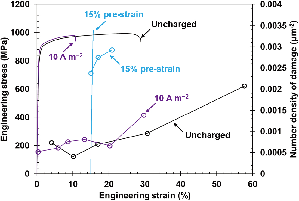
Figure 10 displays the engineering stress–strain curves for specimens with a high pre-strain of 15%, where subsequent hydrogen charging caused immediate failure after yielding. The 15% pre-strained specimen displayed a significant increase in the number density of damage as strain increased, which indicates that the crack initiation probability monotonically increased with increasing pre-strain from 0, 3, 6, and to 15%. The most important characteristic in the 15% pre-strained specimen was the occurrence of fracture after only a slight plastic deformation. To interpret this fracture behavior, we must note three points. The first point, as shown in the previous study,9) is that pre-straining increased the dislocation density before hydrogen charging. Dislocations acted as hydrogen trap sites; hence, hydrogen content increased as the pre-strain level increased at a constant hydrogen-charging condition (e.g., current density). When dislocation-related quasi-cleavage fracture occurs, the increase in hydrogen content at the dislocations plays an important role in cracking in martensite or bainitic ferrite. The previous study reported that the 15% pre-strained specimen showed a quasi-cleavage fracture.9) When the critical hydrogen content for cracking was satisfied before reloading, further plastic strain was not required, which enabled brittle-like fracture without a large plastic deformation.
The second point is the sharpness of the cracks, as shown in Fig. 11. There were numerous sharp cracks in the 15% pre-strained specimen even in the 15% strained region, where most of the strain was provided only by pre-straining (Fig. 11(b)). This indicates that most crack initiation sites were ready for cracking before the reloading, and crack initiation and slight crack-tip blunting occurred simultaneously at multiple sites. Consequently, the growth of the sharp cracks caused the fracture.

The third factor is the occurrence of strain-age-hardening. As displayed in Fig. 10, the maximum stress after reloading was higher than the corresponding flow stress of the uncharged specimen. The increase in the flow stress is attributed to the occurrence of strain aging associated with the dislocation-carbon interaction. Strain-age-hardening plays two roles: (1) the increase in remote stress can mechanically trigger brittle-like cracking, and (2) the subsequent Lüders deformation causes concentrations of stress and strain. The stress concentration occurs on the specimen surface because of the formation of surface relieves, and the strain concentration occurs because of the local softening associated with dislocation depinning20) or mobile dislocation multiplication.21) Figure 12 displays the damage distributions of the 10% strained specimens with and without the effect of Lüders deformation. The specimen containing the effect of Lüders deformation displayed a smooth gradient in the number density of damage compared to that without the effect of Lüders deformation. In particular, the region where the Lüders band propagated demonstrated a higher number density of damage than that of the exterior of the region. In addition, the surface images of the specimens shown in Fig. 13 clearly display the difference in crack distributions between the specimens with and without Lüders deformation. Specifically, in comparison with the surface of the specimen without Lüders deformation (Fig. 13(a)), the interior (Fig. 13(b)) and exterior (Fig. 13(c)) of the Lüders-banded region showed higher and lower numbers of cracks, respectively. These facts indicate that even if the plastic deformation is slight, as shown in Fig. 10, Lüders banding provides locally high stress and strain, which accelerates crack initiation and growth.

In summary, the first and second points clarified that the critical conditions for cracking had been satisfied before reloading. With the high hydrogen concentration that enabled sharp and transgranular crack initiations, the strain-aging-induced hardening and subsequent Lüders deformation triggered the final failure of the 15% pre-strained specimen.
4. Conclusions
Herein, we characterized the pre-strain effects on the hydrogen embrittlement resistance of TBF steel in terms of damage, such as cracks and voids. Specifically, the effects of hydrogen content, austenite fraction, and strain-age-hardening on crack initiation and growth were examined. The findings for the pre-strain effects on hydrogen embrittlement resistance are given as follows:
(1) When the pre-strain was not given, the crack growth resistance was significantly diminished by the hydrogen uptake. However, the degree of degradation was independent of the hydrogen content in the present hydrogen charging condition.
(2) Pre-straining to 3% and 6% improved the crack growth resistance, owing to a reduction in the probability of austenite presence at the crack tip.
(3) Strain-age-hardening caused an increase in yield strength and stress/strain concentration associated with Lüders deformation. The effect of strain-age-hardening diminished the crack initiation resistance and crack growth resistance. When the pre-strain level was high (15%), the strain-age-hardening effects played a critical role in hydrogen-assisted failure.
Acknowledgments
This work was financially supported by JSPS KAKENHI (JP16H06365, JP18K04743, and JP20H02457).
References
- 1) V. F. Zackay, E. R. Parker, D. Fahr and R. Busch: ASM Trans. Q., 60 (1967), 252.
- 2) S. Zaefferer, J. Ohlert and W. Bleck: Acta Mater., 52 (2004), 2765.
- 3) E. De Moor, S. Lacroix, A. J. Clarke, J. Penning and J. G. Speer: Metall. Mater. Trans. A, 39 (2008), 2586.
- 4) K. Sugimoto, M. Tsunezawa, T. Hojo and S. Ikeda: ISIJ Int., 44 (2004), 1608.
- 5) N. Yoshikawa, J. Kobayashi and K. Sugimoto: Metall. Mater. Trans. A, 43 (2012), 4129.
- 6) K. Sugimoto, T. Hojo and J. Kobayashi: Mater. Sci. Technol., 33 (2017), 2005.
- 7) K. Sugimoto, M. Murata and S.-M. Song: ISIJ Int., 50 (2010), 162.
- 8) S. Takagi, Y. Toji, M. Yoshino and K. Hasegawa: ISIJ Int., 52 (2012), 316.
- 9) B. Kumai, T. Hojo, M. Koyama, E. Akiyama, H. Waki and A. Nagasaka: Int. J. Hydrog. Energy, 45 (2020), 27920.
- 10) A. Laureys, T. Depover, R. Petrov and K. Verbeken: Mater. Charact., 112 (2016), 169.
- 11) M. Koyama, T. Ogawa, D. Yan, Y. Matsumoto, C. C. Tasan, K. Takai and K. Tsuzaki: Int. J. Hydrog. Energy, 42 (2017), 26423.
- 12) T. Hojo, B. Kumai, M. Koyama, E. Akiyama, H. Waki, H. Saitoh, A. Shiro, R. Yasuda, T. Shobu and A. Nagasaka: Int. J. Fract., 224 (2020), 253.
- 13) J. A. Ronevich, B. C. De Cooman, J. G. Speer, E. De Moor and D. K. Matlock: Metall. Mater. Trans. A, 43 (2012), 2293.
- 14) C. M. Sturges and A. P. Miodownik: Acta Metall., 17 (1969), 1197.
- 15) W. Y. Choo and J. Y. Lee: Metall. Trans. A, 13 (1982), 135.
- 16) V. K. Verma, M. Koyama, S. Hamada and E. Akiyama: Mater. Sci. Eng. A, 782 (2020), 139250.
- 17) T. Matsuno, D. Maeda, H. Shutoh, A. Uenishi and M. Suehiro: ISIJ Int., 54 (2014), 938.
- 18) T. Hojo, M. Koyama, N. Terao, K. Tsuzaki and E. Akiyama: Int. J. Hydrog. Energy, 44 (2019), 30472.
- 19) M. Koyama, D. Yamasaki, A. Ikeda, T. Hojo, E. Akiyama, K. Takai and K. Tsuzaki: Int. J. Hydrog. Energy, 44 (2019), 26028.
- 20) A. H. Cottrell: Dislocations and Plastic Flow in Crystals, Clarendon Press, Oxford, UK, (1953), 145.
- 21) W. G. Johnston and J. J. Gilman: J. Appl. Phys., 30 (1959), 129.


