Steelmaking
Numerical Investigations on Thermomechanical Behaviour of Purging Plug with Rectangular and Circular Slits
2021 Volume 61 Issue 6 Pages 1826-1834

Details
2021 Volume 61 Issue 6 Pages 1826-1834
Purging plugs are widely used in the secondary refining process, and its service life determines the downtime and usage efficiency of the whole ladle. This study focuses on comparing the heat transfer and thermomechanical behaviour of purging plug with different slits to obtain the reason for the long service life of purging plug by thermal-structure coupling method. The numerical results showed that the moderation of temperature distribution is achieved by changing the slit shape and the reasonable arrangement of the circular slits. Furthermore, the circular slits can alleviate the stress concentration phenomena, and circular slits are better for decreasing the axial stress in the purging plug, which occurred at the position located 0.323 m above the bottom face, and its distance from the centre is 0.04 m.
Ladle refining furnaces are widely employed in the modern steel-making process for decarburization, desulfurization, inclusion removal and homogeneous temperature and composition.1,2,3,4,5,6) As the crucial part of the ladle, purging plugs experience an intermittent thermal shock when the liquid steel is poured into and out of the ladle in cycles during the refining process. Moreover, an intense extra heat exchange occurs within the purging plug when the argon is continuously blown into the liquid steel through the slits assembled in the purging plug. Due to these severe service conditions, the working time of the purging plug, is less than that of the refractory lining of the ladle. Consequently, downtime is needed to repair or replace the purging plug, which leads to more energy consumption and lower production efficiency. Therefore, the service life of the purging plug has long been recognized as an important issue in improving steel-making production efficiency.
In general, the wear of the purging plugs mainly consist of erosion due to intensive liquid steel stirring, corrosion by aggressive iron-oxide rich slag at high temperature and, as well as the spalling of layers from the hot face, which is owing to horizontal cracking.7) In order to prolong the service life of purging plugs, many efforts have been made by adjusting the chemical components so as to improve the material properties. For instance, Long et al.8) compared the relevant thermomechanical properties of corundum-spinel castables produced with and without calcium aluminate cement. Their results showed that higher refractoriness and better iron-oxide-rich slag corrosion resistance could be achieved in the non-cement systems. Then, Pan et al.9) systematically investigated the effect of cement contents on the mechanical properties and found that the phase compositions and microstructure can be optimized through adjusting the cement content in corundum castables. Furthermore, Long et al.10) prepared three kinds of castables, of which physical properties were characterized along with their microstructures at both room temperature and high temperature to increase cold and hot mechanical strengths. It was concluded that the calcium hexaluminate phase in the matrix of the corundum-based low-cement castable enhances the cold and hot mechanical strengths.
As a part of ladle lining, the geometries of the purging plug may also influence their temperature distribution, stress responses, and service life. Hou et al.11) applied Taguchi approaches to facilitate the selection of proper commercial materials and thicknesses of linings for the given process conditions. It was found that two optimal lining concepts were proposed to decrease heat loss through the steel shell and thermomechanical load at the hot face of the working lining. Lin et al.12) proposed three multi-layered lining designs and analyzed the thermo-chemo-mechanical behaviour of SiC-based refractory parts in the linings of waste-to-energy plants. Their results revealed that the localization of the “critical plane” is driven by the thickness of the oxidized area, which is directly related to the temperature field.
Conducting in-situ experiments is the most intuitive approach for investigating the refractory service life. However, in the majority of cases, the measurement limitation and the harsh process environment result in the information provided by the experiments being inadequate. With the continuous increase of the computation resource and numerical technique, the Finite Element method, which is able to afford comprehensive data, becomes a potential tool to investigate the performance of the lining refractory of metallurgical equipment, such as ladle and RH degasser, etc.13) Several numerical simulations have been carried out to reveal the typical practical thermomechanical behaviour of refractory linings present on macrostructures.14,15) In a word, these researches proved the ability of the numerical method to investigate the thermomechanical behaviour of purging plug in service conditions.
Therefore, the present study aimed to explore the heat transfer and stress evolution of purging plug with circular and rectangular slits at service. A 3D numerical model was established to explore the heat transfer and thermal stress evolution of purging plug with circular and rectangular slits at service using the finite element method. To examine the model accuracy, comparisons between the experimental and the numerical results were also conducted. Moreover, the failure mechanism of purging plug with different slits was analyzed using the thermal-structure coupling model, which can provide theoretical support for further structural optimization.
The density of the purging plug, which was made of corundum-spinel castable, is 2900 kg·m−3. The elastic modulus of the purging plug that was sintered at 1873 K is 183 GPa, which is an average value of three specimens measured by impulse excitation technique with RFDA (IMCE, Genk, Belgium) at room temperature16) and the Poisson’s ratio of 0.25 was defined. The thermal conductivity and specific heat capacity were evaluated based on the sintered cylinder samples (Φ12.5 mm × 2 mm) with a laser thermal conductivity meter LFA457 (Netzsch, Germany) applying a laser flash method.17) The thermal expansion coefficient (β) of castable was measured by dilatometer DIL402C (Netzsch, Selb, Germany) on the slip casted cylinder samples (Φ8 mm × 50 mm). The coefficient of thermal expansion (β), thermal conductivity (λ), and specific heat capacity (Cp) were treated as temperature dependent and shown in Fig. 1.

The coefficient of thermal expansion (β), specific heat capacity (Cp), and thermal conductivity (λ) of the corundum castable at different temperatures. (Online version in color.)
In industries, the component with holes was widely employed for various purposes, such as turbine blades,18,19) diesel engine,20) and furnace wall construction.21) However, the stress concentration that often occurs at the corner of the hole determines the failure of the components.22) The geometry of the purging plug with rectangular slits can be found in our previous literature.23) Due to the geometrical symmetry, only one-tenth of the actual purging plug with circular slits was established for conducting the numerical simulation, as shown in Fig. 2. For both types of purging plugs, the cross-section area of slits where the argon was blown in was the same. The dimensions of the purging plugs and slits used are shown in Table 1. In this case, 9.8 × 10⁵ hexahedron eight-node solid elements were assigned to the purging plugs, which meets the requirements of mesh sensitivity.

Schematic of purging plugs with circular slits for numerical simulation. (Online version in color.)
| Type of slit | Circular | Rectangular |
|---|---|---|
| Number of slit | 150 | 30 |
| Argon blowing area (mm2) | 120 | 120 |
| Size of slit | φ=0.55 mm | 0.2*20 mm |
| Diameters for top surface (mm) | 125 | 125 |
| Diameters for bottom surface (mm) | 185 | 185 |
| Height (mm) | 350 | 350 |
The normal cyclic operations consisted of preheating, transporting, stirring and holding stages, and the duration was shown in Table 2. The purging plugs located at the bottom of the ladle, are not only eroded by the flowing molten steel but also experienced strong heat transfer with the blowing gas. Firstly, during the preheating process, the temperature of hot faces was assumed from 673 to 1273 K over 900 s, which was simplified to reduce the computation resources. Subsequently, a transporting procedure was undertaken to transport liquid steel. And after that, a stirring stage was employed to homogenize alloy composition, desulphurization and inclusion removal. Finally, the molten steel was held for casting or transfer to a tundish during the hold stage. As described above, the simplified variation temperature of hot faces follows this equation that was displayed in Fig. 3. At the beginning of the transporting procedure, the temperature of the hot face was changed from 1273 K to 1873 K, which was to simulate the thermal shock from molten steel. At that moment, the steel liquid was poured into the ladle. Thus, it is assumed that the temperature of the hot face is consistent with the temperature of the steel liquid. The heat transfer coefficients (hs) between the slit and argon during the stirring procedure was demonstrated in Fig. 4, which was referred to the authors’ previous paper.23) As shown in Fig. 5, the convection heat transfer coefficient (hc) and the radiation heat transfer coefficient (hr) of the cold face were presented. The heat flux (Qf) between the cylindrical surface of the purging plug and block was shown in Fig. 6, which was calculated from the steady state simulation. Furthermore, the purging plug was constrained at the bottom, and its contact with the block was frictionless, which were shown in Figs. 5 and 6, respectively. In the refining process, the environment temperature and the temperature of molten steel were assumed as 300 k and 1873 K, respectively.
| Process | Duration (s) |
|---|---|
| Simplified preheating | 900 |
| Transporting including tapping | 2400 |
| Stirring | 600 |
| Holding | 900 |

The boundary condition of hot face. (Online version in color.)

The heat transfer between the slit and argon. (Online version in color.)

The boundary condition of cold face. (Online version in color.)

The boundary condition of cylindrical surface. (Online version in color.)
The transient flow of argon gas was injected into the ladle, which enters the slits at the temperature of 300 K. Heat transfer through the slit occurs as a result of the conduction mechanism. The several supports of purging plug together with the temperature gradient around the slits cause a volumetric expansion in purging plug and subsequent thermal stress. Therefore, the thermomechanical behaviour of the purging plug was investigated by two sets of governing equations, including the heat transfer equation and linear elastic equation. The heat transfer equation is defined as:
| (1) |
| (2) |
The elastic material model of the purging plug was employed in this study. The solution of Eq. (1) gives temperature distribution in the purging plug. The linear elastic material governing equation follows:
| (3) |
| (4) |
Where u represents displacement vectors, σ and ε are the stress and strain, respectively. T is the temperature and T0 represent the initial temperature. Due to symmetry in stress and strain tensor, the elasticity tensor D is defined as:
| (5) |
Where v and E are Poisson’s ratio and Young’ modulus, respectively. The relationship among shear stress, Poisson’ ratio and Young’s modulus is given as:
| (6) |
Where, τij is the shear stress tensor. The above equations are applied to calculate applying ANSYS software. Because brittle material such as corundum-spinel castable can resist huge compressive stress but small tensile stress, the tensile stress was considered for analyzing the failure possibility.
2.5. Experimental ValidationFor validating against the numerical model, the experimental apparatus was designed that is indicated in Fig. 7. In this equipment, four thermocouples that were assembled at four measure point, respectively. Considering the safety and the power limited of apparatus, the work face is heated to 1673 K evenly in this experiment. It is well known that the temperature distribution is obviously affected by the turbulence model in stirring procedures. As a consequence, the stirring process was realized in this experimental setup, and the gas flow rate is set to 200 NL/min. Furthermore, the detail of the experiment and simulation is summarized in Table 3. In order to validate with experimental results, a numerical simulation has been performed, in which the boundary condition is the same as the experiment setup.

Schematic of the experimental apparatus including the cutaway view of furnace and thermocouples position. (Online version in color.)
| Process | Duration (s) | Temperature of hot face (K) |
|---|---|---|
| Simplified Preheating | 3600 | 298–1273 |
| Transporting | 2400 | 1273–1673 |
| Stirring | 800 | 1673 |
| Holding | 2400 | 1673 |
The numerical predictions and experimental results of the measuring point are depicted in Fig. 8. It shows that the simulation results are basically distributed near the test temperature results, and the variation trend is consistent. In addition, the difference in the simulation is less than 15% comparing with the measured temperature results of purging plug with rectangular slits. Thus, the boundary conditions that were adopted in simulation can describe the gas stirring process well.

The temperature distribution of test point in simulation and experiment. (Online version in color.)
The temperature distributions of the purging plug with different slits were indicated in Fig. 9. It shows that the purging plug experiences an abrupt temperature change when the operation condition is changed in the refining process. Apparently, in either purging plug, a larger temperature gradient could be observed at the end of the stirring stage. But a few differences were observed in the centre of two types of purging plugs except at the end of the stirring stage comparing the temperature distribution of purging plug with different slits, which is because there is abrupt heat convection between blowing gas and slit wall. Thus, the impact of the shape of slits on temperature distribution has to be deeply analyzed by both axial and radial cross-sections during the stirring stage in the following section.

Temperature distributions in the purging plug with (a. b. c. d) rectangular slits and (e. f. g. h) circular slits at (a) (e) the end of preheating, (b) (f) the end of transporting, (c) (g) the end of stirring and (e) (h) the end of casting. (Online version in color.)
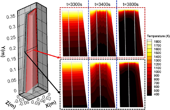
Figure 10 shows the temperature distribution of the purging plugs with rectangular slits at radial cross-sections during the stirring process. The results indicated that a large temperature gradient was located near the hot face owing to the heat transfer between liquid steel and the purging plug. In addition, there is the heat flux between the argon-blown pocket block and purging plug during the stirring period. As a consequence, the temperature gradient that was situated near the cylindrical face increases with stirring time. As seen in Fig. 11, the temperature distribution of the purging plugs with rectangular slits at radial cross-sections during the stirring process was displayed. Comparing with Fig. 10, it can be found that the temperature gradient of purging plugs with circular slits located near the hot face is smaller than that of purging plug with rectangular slits at 3800 s. The possible reason for this phenomenon is originated from evenly and widely arranged circular slits.

Temperature distribution of purging plugs with rectangular slits at radial cross-sections during stirring process. (Online version in color.)
Temperature distribution of purging plugs with circular slits at radial cross-sections during stirring process. (Online version in color.)
To investigate the temperature gradient around different slits, the temperatures at different axial cross-sections during the stirring process were compared. Figure 12 depicts the temperatures of purging plug with rectangular slits at different axial cross-sections. It is evident that the temperature around the slits decreased with blowing. Figure 13 shows the temperatures of the purging plug with circular slits at different axial cross-sections. It was indicated that the temperature distribution around circular slits at axial cross-section is more even than that around rectangular slits. In addition, similar to Fig. 12, the closer to the hot face the cross-section locates, the higher the temperature of the cross-section is. These phenomena demonstrated that competition between the heat transfer from molten steel and the heat loss carried away by flowing gas during the stirring stage. For the same reason, the cross-section where is near the hot face has a larger temperature gradient. Furthermore, the temperature gradient of the whole purging plug with circular slits is also smaller than that of the purging plug with rectangular slits, since the circular slit were evenly and widely arranged in the purging plug. Evidently, the more evenly the slits were placed, the more evenly the temperature was distributed.

Temperature distribution of purging plugs with circular slits at axial cross-sections during stirring process. (Online version in color.)

Temperature distribution of purging plugs with rectangular slits at different cross-sections during stirring process. (Online version in color.)
Generally speaking, the heat flux of the cylindrical surface will aggravate the heat loss of the purging plug in service. Furthermore, heat transfer from molten steel will heat up the purging plug. During the stirring stage, the blowing gas will cool down the slit wall. If the competition among three heat transfer that was mentioned above can be reasonably balanced, the temperature drop of the purging plug will be reduced. Before changing the slit shape, the long edges of the rectangular section were arranged radially, and the rectangular slits arranged in two layers were assembled too close to each other. After changing the shape and arrangement of the slit, the circular slits were arranged in two layers around the circumference and throughout the purging plug in the axial direction. In addition, the number of circular slits increases gradually from the inside to the outside. Thus, the heat loss of the purging plug was reduced due to the interaction of heat flux and the heat transfer between the slit wall and blowing gas. So the reasonable arrangement of the circular slit can lead to the more uniform temperature distribution. Therefore, the moderation of temperature distribution is achieved by changing the slit shape and the reasonable arrangement of the circular slits.
3.2. Thermomechanical ResultsAs shown in Fig. 14, in general, the compressive stress occurs at the centre of the purging plug with rectangular slits, and the stress distribution is relatively gentle. Moreover, the area, where is the tensile stress, is the largest at the stirring stage, and the maximum axial stress is observed at point A that is located at y = 0.323 m, and the distance from the centre is 0.04 m in this process. Location A was chosen to analyze the axial stress evolution for the whole process operation. Figure 15 shows that the maximum axial stress of the purging plug with rectangular slits decreases by 66.6% comparing with that of the purging plug with circular slits at point A. Besides, the axial stress increased abruptly during the stirring process and reached the maximum at approximately 3400 s when argon was blown into slits.

Axial stress distribution in the purging plugs with (a. b. c. d) rectangular slits and (e. f. g. h) circular slits at (a) (e) the end of preheating, (b) (f) the end of transporting, (c) (g) the end of stirring and (e) (h) the end of casting. (Online version in color.)

Variation in axial stress with time of position A for purging plug with different slits. (Online version in color.)
To obtain stress distribution inside purging plug, the axial stress of purging plug at radial cross-section were compared. Figure 16 shows that axial stress distribution of purging plugs with rectangular slits at radial cross-sections during the stirring process. It further demonstrated that the axial tensile stress located at y = 0.323 m and the distance from the centre is 0.04 m in the stirring process. Moreover, the maximum compressive stress is located at the central axis. As shown in Fig. 17, the axial stress distribution of purging plugs with circular slits at radial cross-sections during the stirring process was displayed. It shows a well-distribution of axial stress near the hot face at the beginning of the stirring stage. Due to heat convection between gas and purging plug, the temperature gradient around slits rapidly increased. As a result, the axial stress around the slit was raised with a temperature gradient; this phenomenon can also be found around rectangular slits. Comparing Figs. 16 with 17, the compressive stress located at the central axis has been effectively modified by replacing the shape of the slit.

Axial stress distribution of purging plugs with rectangular slits at radial cross-sections during stirring process. (Online version in color.)

Axial stress distribution of purging plugs with circular slits at radial cross-sections during stirring process. (Online version in color.)
For analyzing the stress inside the purging plug, the stress contour around rectangular slits during the stirring process was presented in Fig. 18. It shows that the stress gradient around the rectangular slit is significant. Besides, the stress gradient increases with stirring time. Figure 19 depicts the stress contour around rectangular slits during the stirring process. This figure reveals that the stress around the circular slits gradually increases with the increase of axial distance. Comparing with Fig. 18, it can be concluded the axial stress around the rectangular slit is highly concentrated, but the stresses around the circular slits are well distributed. According to previous researches,24,25,26) the geometric structure of the component affects the stress distributions. Moreover, it is well known that the stress will concentrate on the corner of slit.27,28) Therefore, it can be concluded that the stress distribution is affected by the shapes of the slits, and the circular slits are much better for reducing the maximum axial stress of a purging plug, which is the main cause of the fracture. Consequently, the cracks that cannot be avoided in the preparation of castable tend to propagate around the rectangular slit more easily. Furthermore, as the circular slits were evenly arranged in the purging plug, the temperature was distributed more evenly in them than the purging plug with rectangular slits. As a consequence, the stress distributions of purging plug with circular slits were more evenly than that of purging plug with rectangular slits.

Axial stress distribution of purging plugs with rectangular slits at axial cross-sections during stirring process. (Online version in color.)

Axial stress distribution of purging plugs with circular slits at axial cross-sections during stirring process. (Online version in color.)
To investigate the transverse fracture of the purging plug in axial direction, the displacement is shown in Fig. 20. This contour indicates that the maximum displacement of 0.81 mm was occurred in the purging plug with rectangular slits, and the maximum displacement of 0.72 mm was occurred in the purging plug with circular slits. Owing to evenly arranged circular slits, the temperature gradient inside the purging plug was reduced. Therefore, the temperature gradient was lower than that of purging plug with rectangular slits in both cross-section and axial direction. Subsequently, the height of displacement region that were dashed in purging plug with rectangular slits ωr is larger than ωc that of purging plug with circular slits. Under the periodic thermal load, the spalling of layers from the hot face occurs. Referring to the previous research,23) it can be found that this displacement position of purging plug with rectangular slits is agreed with the practical fracture phenomena that also was considered as spalling well. Comparing with purging plug with rectangular, the spalling of purging plug with circular slits is lesser in industry.

Displacement of purging plug (a) rectangular slits and (b) circular slits when t = 3400 s. (Online version in color.)
In the present work, the thermal-solid model was applied to investigate the temperature field and thermomechanical behaviour of purging plug with two types slit. The following conclusions can be drawn:
(1) The moderation of temperature distribution is achieved by changing the slit shape and the reasonable arrangement of the circular slits.
(2) The stress concentration around the slit can be alleviated by changing the shape of the slit.
(3) The thermomechanical modeling shows that the circular slits can reduce the maximum axial stress in a purging plug by 66.7% comparing with that of the purging plug with rectangular slits, which occurred at y = 0.323 m, r = 0.04 m.
This work was financially supported by the National Natural Science Foundation of China [Grant numbers. 51974211] and the Special Project of Central Government for Local Science and Technology Development of Hubei Province [Grant numbers. 2019ZYYD003, 2019ZYYD076].