Forming Processing and Thermomechanical Treatment
Vertical Vibration Characteristics of Strip Rolling Mill under Compound Roll Bearing Failure
2022 Volume 62 Issue 1 Pages 179-190
Details
2022 Volume 62 Issue 1 Pages 179-190
A vertical vibration model of a 3-DOF strip rolling mill with a compound roll bearing failure on the outer raceway and inner raceway is established. Through MATLAB simulation, the vertical vibration characteristics of the strip mill work roll are compared and analyzed under the condition that the outer raceway failure of the roller bearing remains unchanged, the inner raceway failure changes and the inner and outer raceway failures change simultaneously. It provides a certain theoretical basis for further clarifying the non-linear vibration mechanism of the rolling mill caused by the compound bearing failure. At the same time, when the internal and external raceways of the roller bearing have a compound failure, the effects of different roller numbers and contact angles on the vibration displacement fluctuations of the work roll are analyzed, which has certain theoretical guidance for the optimization design of the roll bearing.
Rolling mill vibration1,2,3,4) has always been a technical problem for the steel industry at home and abroad. Due to the quality deviation of rolling products and damage to rolling equipment caused by vibration, it will cause serious loss of rolling productivity.5) Due to the complex structure of the rolling mill, the causes of the rolling mill’s vibration are also various.6,7,8,9) Therefore, researchers at home and abroad have launched a series of theoretical studies. Fujita et al.10) found that the friction force of each stand of the rolling mill is different, so considering the balance of the friction coefficient of multiple stands, proposed an intelligent lubrication control system to prevent chattering, which can prevent chattering during high-speed cold rolling effectively. Wang et al.11) studied the rolling mill system dynamics of the unstable lubricating state of the gap between two rolls during the rolling mill operation. And analyzed the corresponding distributions of the friction and pressure with varying surface roughness and time in unstable lubrication conditions systematically. Then the influence of main rolling parameters on the critical velocity and amplitude of self-excited vertical vibration was studied. Wu et al.12) established a rolling force fluctuation model based on changes in rolling forces between the front and rear sliding zones. Then, in order to analyze the vibration characteristics of the Sendzimir 20-high cold rolling mill, a dynamic model of vertical and horizontal vibration coupling was established. It is found that the occurrence of vibration marks can greatly increase the fluctuation amplitude of the rolling force, and the rolling mill vibration can be suppressed by reducing the rolling speed. Sun et al.13) built a nonlinear vibration model of the tension of the steel strip between two rolling mills as the tension changes over time. They found both the speed and the thickness of the rolled strip have great influences on the stability of fundamental parametric resonances. Lu et al.14) proposed a dynamic incremental model of chattering for a Universal Crown Controlled rolling mill with the considering the hardening of the strip and the elastic deformation of the work rolls, nonlinear friction, transfer delay of the strip and the dynamic coupling effect of the strip tension between adjacent stands. Then, a novel time-varying stability criterion to evaluate the stability of the rolling mill was proposed. Finally, further studied the optimal friction coefficient and reduction ratio needed to increase the critical rolling speed and vibration stability in a tandem cold rolling mill. Tang et al.15) established the parameterized bending vibration equation of the strip during rolling, and studied the unsteady state of the rolling mill vibration caused by the strip bending vibration. At the same time, the natural frequency of the bending vibration of the strip was found to be close to half of the harmonic current frequency of the main current in the drive motor.
Except rolling process parameters, the use of rolling equipment also has an important impact on rolling mill vibration.16,17,18) In the hot rolling process, faster and harder rolling is required to obtain thinner, higher quality strips. In order to cope with the greater impact generated during the rolling process, a rolling mill stabilizing device composed of a hydraulic cylinder with a hole is used in actual production. Furumoto et al.19) proposed that a cavity be installed in the hydraulic cylinder of the rolling mill stabilizing device, which further improves the damping effect of the stabilizing device and weakens rolling mill vibration. Wu et al.20) found a rare frequency modulation phenomenon during fieldwork to measure the vibration of high-speed rolling mills. Then analyzed the rolling mill amplitude and frequency modulation caused by the rigidity of the roll bearing in a fixed direction and periodic variation of the effective error of the bearing possibly, finally found that the frequency modulation is caused by the 12 ripples on the inner raceway of the roller bearing by comparing the theoretical analysis results with the test results. Roll bearings are important equipment of rolling mills, their running status will also affect rolling production because of a high unit load.21,22,23) In the current research, the role of roll bearings is often ignored. Especially when there are some minor faults in the bearings, these faults may also become the source of the rolling mill excited vibration.
Therefore, in this paper, a 3-DOF vertical vibration model of strip mills with compound failure of the inner and outer raceways of work roll bearings is established. The failure on the inner raceway of the roller bearing is a single-point closed elliptical pit fault, and the failure of the outer raceway is a single-point partially rectangular pit fault. The vertical vibration characteristics of the strip mill with the compound failure of work roll bearings were studied by numerical simulation.
Roll bearing inner raceway failure adopts a single-point closed elliptical pit failure.24)
There is a clear difference between the inner raceway failure and the outer raceway failure, that is, the inner raceway is fixedly mounted on the work roll, so when the mill works, the fault point on the inner raceway will rotate with the work roll. During a full rotation, the fault point is sometimes in the load area, sometimes outside the load area.
The angular range of the load area determined by the radial clearance25) is
| (1) |
For the convenience of calculation here, we assume that the clearance is zero, then ψ=90°.
Then the angle range of its load zone on the entire bearing inner raceway is ∆ψ=(5/4π, 7/4π).That is, in this load area, the change in the contact stress of the roller raceway will occur when the roller contacts the fault zone of the inner raceway, which will affect the normal work of the rolling mill. When the fault spreads to a certain extent, it will cause the rolling mill to vibrate.
Since the failure is located on the inner raceway of the roller bearing, it is necessary to consider whether the roll moves to the inner raceway fault area and whether the inner raceway failure moves to the entire bearing load area of the roll bearing.
Considering the geometry of the work roll bearing and the kinematic relationship between the roll and the inner ring, during the operation of the work roll bearing, at the time t, the relative radian angle position of the center point of the single-point elliptical fault zone and the contact line of the inner raceway and the j-th roller is
| (2) |
| (3) |
| (4) |
| (5) |
Assuming that the starting point of the center of the single-point elliptical fault zone of the inner raceway is located at three o’clock relative to the outer raceway of the fixed work roll bearing, then by calculation a new decision relationship can be obtained as follows
| (6) |
| (7) |
Through formula (6), the effective contact length between the roller and the raceway can be accurately calculated at any time.
| (8) |
The contact between the steel roller and the raceway is a linear contact, and its contact stiffness26) is
| (9) |
In order to simplify the calculation in this article, it is considered that the contact stiffness between the roller and the inner and outer raceways is equal, that is
| (10) |
Then the total contact stiffness of the outer and inner raceways of the bearing can be calculated according to the following formula
| (11) |
The total contact stiffness of the inner and outer raceways of the work roll bearing and the j-th roller is calculated as
| (12) |
A local failure model of the raceway is established on the outer raceway of the work roll bearing, as shown in Fig. 1

Local defect on bearing outer raceway.

Local defect sectional view of bearing outer raceway.
In Fig. 1, w is the depth of the local fault (this article assumes that w is sufficiently deep, when the contact deformation of the rollers with the inner and outer raceways reaches the maximum, the conical surface of the rollers will still not touch the bottom of the partial failure).
| (13) |
It can be seen from Fig. 1 that when the roller passes the fault zone, the amount of contact deformation of the roller and the inner and outer raceways is a variable. The deformation release increases gradually at the beginning, when the roller reaches the center of the fault area, the deformation release reaches the maximum, when the roller continues to roll, the deformation release decreases gradually until the roller amount of deformation release is zero.
For this process, in order to simplify the calculation, Liu et al.27) directly idealized the gradual process of the deformation release of the roller through the fault area, making it equivalent to a sine function, and its change trend is shown by the dashed line in Fig. 2.

Comparison of the contact deformation release form of the roller and the raceway when the bearing roller passes the failure on the raceway (b=2 mm, n=3 r/min).
When the roller is located in the position shown in Fig. 1(a), the maximum amount of contact deformation between the inner and outer raceways of the roller is released. The maximum amount of deformation relative to the normal of the outer raceway is
| (14) |
As shown in Fig. 3, considering the process of rollers passing through local faults, it can be found that the amount of contact deformation between the inner and outer raceways of the roller is a variable which is related to the position of the roller at the local fault. When the roller is in the local fault area and rolls through the fault area at the angular velocity ωa, we can understand this process as the amount of deformation release increases or decreases with the position of the roller based on the side where the fault area is in contact with the roller. The process of the roller moving from the faulty A side to the B side can be divided into two steps. First, the roller rolls from the A side of the fault area to the B side of the fault area. At this time, it can be regarded as a virtual edge B’ also contacts the roller and moves to the right until B’ and B coincide, and the roller axis Reached the center of the local failure, the contact deformation between the inner and outer raceways of the roller reached the maximum. Then, when the roller continues to roll to the B side, it can be regarded as another virtual edge A’ also contacts the roller and moves to the right. Until A’ and B coincide, the roller completely passes the fault zone, then at this time, the amount of contact deformation between the inner and outer raceways of the roller also becomes zero. After analysis, it can be obtained that during the entire rotation process, the change law of the amount of contact deformation between the inner and outer raceways of the roller is
| (15) |

The process of a bearing roller passing through the local fault zone.
In the above formula
| (16) |
| (17) |
In order to verify the above reasoning, Adams software was used to perform kinematics simulation on the process of local failure of the roller passing the outer raceway of the bearing. Derive the simulation data and generate the motion curve (solid line part) through MATLAB and compare it with the conjecture of this article and Liu’s hypothesis, as shown in Fig. 2. It is found that the theoretical guess (dotted line) and Adams simulation curve (solid line) fit better.
Since the work roll bearing studied in this paper is a tapered roller bearing, when the tapered roller passes through the local fault area of the outer raceway, the contact deformation in the vertical and axial directions is
| (18) |
| (19) |
Then the contact deformation δj(t) of the j-th roller between the inner and outer raceways of the bearing can be obtained as
| (20) |
It can be obtained that the total contact force Fb(x2–x3)25) between the roller and raceways under the compound bearing failure is
| (21) |
| (22) |
| (23) |
| (24) |
Considering the influence of the contact force of the work roll bearing with the compound failure of the roll bearing in formula (21), a 3-DOF vertical vibration model of the rolling mill with the compound failure of the inner and outer raceways of the work roll bearing can be established, as shown in Fig. 4.

3-DOF vertical vibration model of rolling mill with compound roll bearing failure.
Using the rolling mill vertical vibration model of the four-high rolling mill in Fig. 4 the dynamic equations of the 3-DOF vertical vibration model of the 4-high rolling mill with a compound failure of the inner and outer raceways of the roll bearing are now given by
| (25) |
The corresponding simulation calculation program is written in formula (25) with the fourth-order Runge-Kutta method, and the actual parameters of the R1 roughing mill of the 1780 hot rolling mill in a certain factory are used in the simulation are shown in Table 1.
| Description | Value | Description | Value |
|---|---|---|---|
| m1/kg | 7.59×10⁴ | m2/kg | 1.596×10⁴ |
| m3/kg | 6.34×10³ | k0/N∙m−1 | 2.566×10¹⁰ |
| k1/N∙m−1 | 3.241×10¹⁰ | k2/N∙m−1 | 5.948×10¹⁰ |
| k3/N∙m−1 | 1.184×10¹¹ | c1/ N∙s∙m−1 | 3×10⁶ |
| c2/ N∙s∙m−1 | 5×10⁵ | c3/ N∙s∙m−1 | 3×10⁵ |
It can be seen from Fig. 5(a) that the work roll exhibits a more complex vibration behavior under the composite failure of the inner and outer raceways of the work roll bearing. Spectrum analysis of its vibration displacement is shown in Fig. 5(b). There are four frequencies, which are the fundamental frequency (faxis) of the work roll rotation, the single point fault frequency (fo) of the outer raceway, the single point fault frequency (fi) of the inner raceway, and the first natural frequency (f1) and the second natural frequency (f2) of the rolling mill vibration system. Among them, the amplitude of the 12fo is the largest. The amplitude of f2 is the smallest. From the perspective of energy, the former has the strongest, and the latter has the weakest.
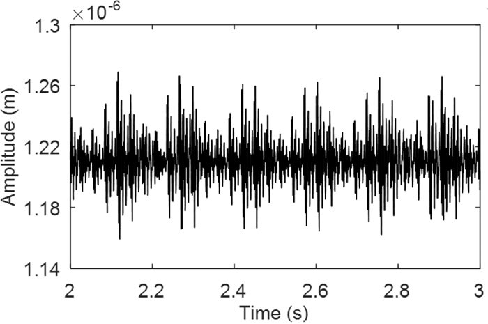
Vibration displacement the work roll with compound defect on the work roll bearing (S=8.75π mm2, n=100 r/min).

Spectrum of the work roll vibration displacement with compound defect on the work roll bearing (S=8.75π mm2, n=100 r/min).
From Fig. 6(b), the frequency components of the vibration displacement spectrum of the work roll are analyzed, and the fundamental frequency of the work roll rotation faxis and its two-fold frequency 2faxis, three-fold frequency 3faxis, and six-fold frequency 6faxis are more obvious, among which the energy of the six-fold frequency is the largest, which is consistent with the fundamental frequency of the work roll rotation and causes the resonance, and from Fig. 7(b), it is the resonance caused by the five-fold frequency 5faxis. From Figs. 6(a) and 7(a), it can be seen that the frequency doubling causes the periodic vibration of the work roll, and comparing the amplitude of the two, the resonance amplitude caused by the six-fold frequency 6faxis is greater, so we can come to a conclusion that the resonance caused by six-fold frequency 6faxis at the speed n=1225 r/min is more serious to the damage of the work roll.
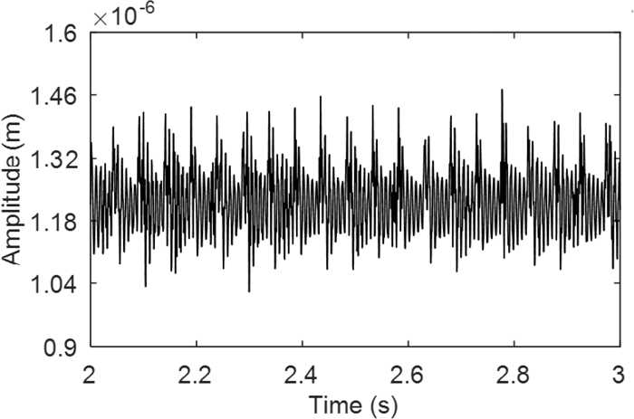
Vibration displacement of the work roll with compound defect on the work roll bearing (S=560π mm2, n=1225 r/min).

Spectrum of the work roll vibration displacement with compound defect on the work roll bearing (S=560π mm2, n=1225 r/min).

Vibration displacement of the work roll with compound defect on the work roll bearing (S=560π mm2, n=1470 r/min).

Spectrum of the work roll vibration displacement with compound defect on the work roll bearing (S=560π mm2, n=1470 r/min).
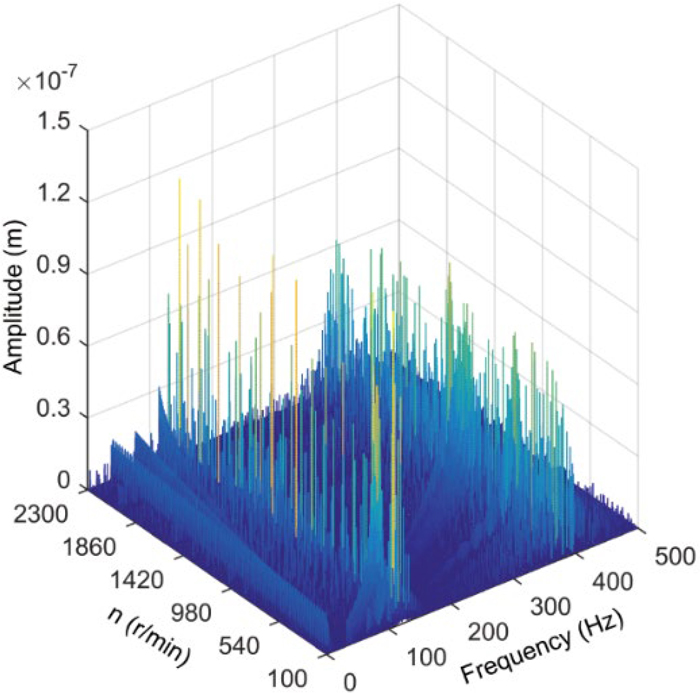
In order to study the influence of the single-point failure of the inner raceway on the vibration behavior, firstly, the failure of the outer raceway is set unchanged, and the failure of the inner raceway gradually becomes larger. Figures 8, 9, 10, 11, 12, 13 are the waterfall diagrams of the vertical vibration displacement spectrum of the work roll under the change of the work roll speed when the area of the single point failure area of the inner raceway gradually increases.

The frequency spectrum waterfall of the vibration displacement of the work roll with the change of the work roll rotation speed (S=8.75π mm2, b=2 mm). (Online version in color.)
The frequency spectrum waterfall of the vibration displacement of the work roll with the change of the work roll rotation speed (S=35π mm2, b=2 mm). (Online version in color.)

The frequency spectrum waterfall of the vibration displacement of the work roll with the change of the work roll rotation speed (S=140π mm2, b=2 mm). (Online version in color.)

The frequency spectrum waterfall of the vibration displacement of the work roll with the change of the work roll rotation speed (S=315π mm2, b=2 mm). (Online version in color.)

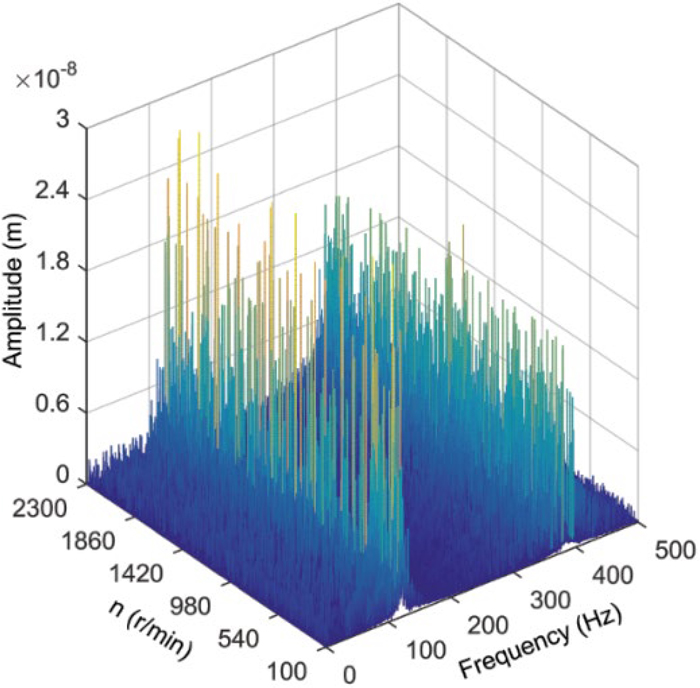
The frequency spectrum waterfall of the vibration displacement of the work roll with the change of the work roll rotation speed (S=560π mm2, b=2 mm). (Online version in color.)

The frequency spectrum waterfall of the vibration displacement of the work roll with the change of the work roll rotation speed (S=875π mm2, b=2 mm). (Online version in color.)
It can be seen from Figs. 8 and 9 that when the area of the single-point closed pit failure area of the inner raceway is 8.75π mm2 and 35π mm2 respectively, the single-point failure of the inner raceway and the single-point failure of the outer raceway are relatively weak. The characteristic frequency of is more complicated, and the rolling mill has a more complicated resonance behavior. Observing Fig. 5(b), we can see that the frequency component with the largest amplitude is the frequency component of the single-point fault frequency of the outer raceway. Therefore, the energy of these frequencies is greater and the rolling mill is more prone to superharmonic resonance. When the rotation speed is increased from 100 r/min to 2300 r/min, resonance will occur in the whole process, where the inner ring fault frequency corresponding to the rotation speed n is close to the first and second natural frequencies of the rolling mill vibration model. The primary resonance of the rolling machine occurs.
It can be seen from Figs. 8, 9, 10, 11 that when the area of the single-point failure area of the outer raceway of the work roll bearing is smaller than S=315π mm2, as the area of the failure area increases, the first and second order inherent in the rolling mill vibration model, the primary resonance intensity of the frequency is also increasing, and the amplitude reached 9.2×10⁻⁸ m and 7.1×10⁻⁸ m, respectively. Comparing the amplitudes of the above two, it is found that the intensity of the resonance caused by the first natural frequency is the strongest.
It can be seen from Fig. 12 that when the area of the raceway failure area in the work roll is S=560π mm2, there are two resonance states that can be equal to the severity of the primary resonance, and the fundamental frequency speed is 1225 r/min and 1470 r/min, the corresponding rotational fundamental frequencies are 20.3 Hz and 24.5 Hz, respectively, which are 1/6 and 1/5 of the first-order natural frequency of the rolling mill vibration model, as shown in Figs. 6(b) and 7(b), which shows that the characteristic frequencies of the two superharmonic resonances are the five-fold frequency 5faxis and the six-fold frequency 6faxis of the fundamental frequency of the work roll rotation.
As shown in Fig. 13, when the area of the closed elliptical fault area of the work roll bearing is S=875π mm2, the vibration amplitude of the primary resonance is reduced to about 3×10⁻⁸ m, it can be seen that the fundamental frequency of the work roll rotation. The amplitudes of frequency double and triple frequency exceed the amplitudes corresponding to the first and second natural frequencies of the rolling mill vibration system in the primary resonance. When the rotation speed reaches 2300 r/min, the fundamental frequency amplitude of the work roll rotation reaches 4.3×10⁻⁸ m, the double frequency amplitude reaches 4×10⁻⁸ m, and the triple frequency amplitude reaches 8.7×10⁻⁸ m, which is the maximum of. There are two most severe vibration states, namely, the super-harmonic resonance behavior caused when the five-fold and six-fold of the fundamental frequency of the work roll rotation are consistent with the first-order natural frequency of the rolling mill vibration system. The roller speed is 1225 r/min and 1470 r/min, and the corresponding amplitude of the first-order natural frequency reaches 1.2×10⁻⁷ m and 9.5×10⁻⁸ m. The resonance behavior caused by the second-order natural frequency of the rolling mill vibration model has been greatly reduced. The five more obvious resonance peaks correspond to the speed of 1275 r/min, 1530 r/min, 1650 r/min, 2100 r/min, and 2295 r/min, corresponding to the fundamental frequency 18 times, 15 times, 14 times, 13 times, 11 times, 10 times the second-order natural frequency super-harmonic resonance, of which 10 times the frequency the induced superharmonic resonance is the most intense. At this time, the speed is 2295 r/min, and the amplitude of the second-order natural frequency reaches 4.8×10⁻⁸ m.
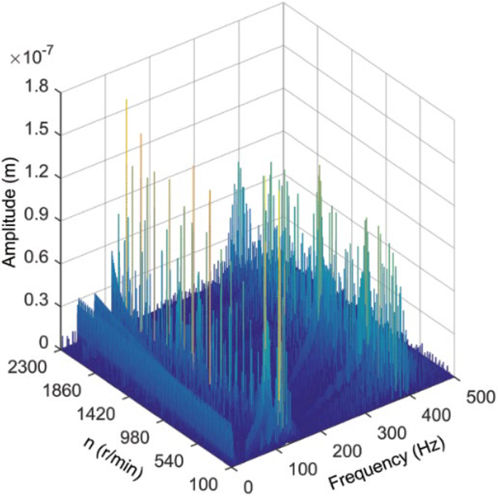
4.2. Vertical Vibration Characteristics of Rolling Mills with Simultaneous Changes of the Compound Failure on Inner and Outer Raceways of Roll BearingsIn factory production, when both the inner and outer raceways of the work roll bearing are faulty, it is often impossible to expand only the failure of the inner raceway or the outer raceway, but to expand into more serious faults simultaneously. According to the compound fault variable set in Table 3, a waterfall spectrum chart of the vertical vibration displacement of the work roll under the change of the work roll rotation speed is made as shown from Figs. 14, 15, 16, 17, 18, 19.
| Variable/Unit | Value | Variable/Unit | Value |
|---|---|---|---|
| do/mm | 900 | di/mm | 710 |
| Do/mm | 845 | Db/mm | 49.8 |
| Le/mm | 53.64 | Z | 42 |
| α | 13°8′21″ |
| Compound failure variable | de1 | de2 | de3 | de4 | de5 | de6 |
| Outer raceway failure (b/mm) | 1 | 2 | 3 | 4 | 5 | 6 |
| Inner raceway failure (S/mm2) | 8.75π | 35π | 140π | 315π | 560π | 875π |
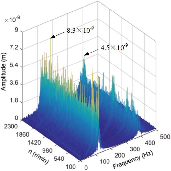
The frequency spectrum waterfall of the vibration displacement of the work roll with the change of the work roll rotation speed (de1). (Online version in color.)

The frequency spectrum waterfall of the vibration displacement of the work roll with the change of the work roll rotation speed (de2). (Online version in color.)

The frequency spectrum waterfall of the vibration displacement of the work roll with the change of the work roll rotation speed (de3). (Online version in color.)
The frequency spectrum waterfall of the vibration displacement of the work roll with the change of the work roll rotation speed (de4). (Online version in color.)
The frequency spectrum waterfall of the vibration displacement of the work roll with the change of the work roll rotation speed (de5). (Online version in color.)

The frequency spectrum waterfall of the vibration displacement of the work roll with the change of the work roll rotation speed (de6). (Online version in color.)
It can be seen from Fig. 14 that when the compound fault variable is de1, since the inner and outer raceway both have faults at the same time, the characteristic frequency is more complicated. At this time, the single-point fault of the inner and outer raceways both are the minimum values of the fault severity set by simulation, its resonance behaviors are weak. The primary resonance is the most serious when the single-point fault frequency of the raceway in the work roll bearing is consistent with the first-order natural frequency and the second-order natural frequency of the rolling mill vibration model. The amplitude of the primary resonance is 8.3×10⁻⁹ m when the first-order natural frequency occurs, when the primary resonance occurs at the second natural frequency, the amplitude reaches 4.5×10⁻⁹ m. At this time, the single-point failure of the inner raceway of the work roll bearing is more serious than the partial failure of the outer raceway. The energy of the single-point fault frequency is relatively large, which causes the primary resonance of the rolling mill.
As shown in Fig. 16, when the compound fault variable is de3, the single-point local fault frequency of in the outer raceway and the inner raceway are consistent with the first and second natural frequencies of the rolling mill vibration model, primary resonance occurs respectively. When the single-point fault frequency of the outer raceway is equal to the first-order and second-order natural frequencies, the amplitudes reach 7.8×10⁻⁸ m and 5.7×10⁻⁸ m, respectively; when the single-point fault frequency of the inner raceway is the same as the first-order When the second-order natural frequencies are equal, the amplitudes reach 7.2×10⁻⁸ m and 4.8×10⁻⁸ m respectively. It is found that the amplitudes of the natural frequencies corresponding to the two main resonances are close by comparison. This shows that the severity of the local fault of the outer raceway at this time is almost equal to the single-point closed pit fault of the inner raceway, which means that the energy values corresponding to their characteristic frequencies are equal.
It can be seen from Figs. 15, 16, 17, 18 that the primary resonance amplitude value caused by the single-point fault frequency of the inner raceway gradually decreases with the increase of the severity of the composite fault, while the primary resonance amplitude value caused by the single-point fault frequency of the outer raceway increases with the increase in the severity of compound faults gradually increases. The failure rate of the outer raceway becomes serious faster than that of the inner raceway, so the energy of the failure frequency of the outer raceway is greater than that of the inner raceway, which is more likely to cause the main resonance of the rolling mill.
In Fig. 19, the severity of the failure of the outer raceway is greater than the failure of the inner raceway, only when the frequency of the single-point failure of the outer raceway of the work roll bearing is consistent with the first-order natural frequency and the second-order natural frequency of the rolling mill vibration model. The primary resonance of the rolling mill is triggered when the first-order natural frequency is the most serious, and its amplitude is 2.2×10⁻⁷ m, and the vibration amplitude corresponding to the second-order natural frequency is 1.6×10⁻⁷ m; Secondly, the single-point fault frequency of the outer raceway of the work roll bearing and the 1/2 super-harmonic resonance produced by the rolling mill vibration model are also more obvious; Finally, when the rotation speed of the work roll is 1225 r/min and 1470 r/min, the super-harmonic resonance behavior caused when the fundamental frequency of the work roll rotation is the same as the natural frequency of the rolling mill vibration system is also obvious. The vibration amplitude reached 1.3×10⁻⁷ m and 9.9×10⁻⁸ m; In the entire speed range, it can be seen that the fundamental frequency of the work roll rotation and the amplitudes of its double and triple frequencies are relatively large. When the rotation speed is 2300 r/min, the amplitude is the largest, the fundamental frequency amplitude of the work roll rotation is 5.1×10⁻⁸ m, the double frequency amplitude is 4.7×10⁻⁸ m, and the triple frequency amplitude is 8.6×10⁻⁸ m.
It can be seen in Figs. 14, 15, 16, 17, 18, 19 that with the increase of the severity of the compound faults of the inner and outer raceways of the work roll bearing, the amplitude of the first and second natural frequencies of the rolling mill are constantly increasing when the main resonance occurs. The amplitude of the first natural frequency increases from 8.2×10⁻⁸ m to 2.2×10⁻⁷ m, and the amplitude of the second natural frequency increases from 4.2×10⁻⁹ m to 1.6×10⁻⁷ m. This means that the more serious the compound failure of the roll bearing, the more severe the main resonance of the mill caused by its failure frequency.
Figure 20 shows the influence of the different compound fault variable of work roll bearings on the work roll vibration Peak acceleration value, RMS value, Peak factor and Kurtosis value when the work roll speed is 100 r/min.

Influence of the compound defect variable on the Peak value of the work roll vibration acceleration (n=100 r/min).

Influence of the compound defect variable on the RMS value of the work roll vibration acceleration (n=100 r/min).

Influence of the compound defect variable on the Peak factor value of the work roll vibration acceleration (n=100 r/min).

Influence of the compound defect variable on the Kurtosis value of the work roll vibration acceleration (n=100 r/min).
The curve in Fig. 20(a) is roughly consistent with the trend shown in Fig. 20(b). Turning points of the two curves appear at the fault variables de5 and de4 in Figs. 20(a) and 20(b), respectively. That is, the vibration acceleration of the roller is reduced to a certain extent in the later stage of the expansion of the bearing compound fault variable. The change of the vibration speed has slowed down.
The Peak factor curve in Fig. 20(c) shows a rise and then a slow decrease, which indicates that as the fault variable changes, the work roll vibration acceleration first increases and then slowly decreases. The ability of the work roll’s vibration acceleration to increase with the corresponding peak vibration increases firstly and then decreases slowly.
Figure 20(d) shows that when the roll bearing compound fault variable is changed from de1 to de4, the distribution pattern of the rolling vibration acceleration becomes more and more flat at the tail. When the roll bearing compound fault variable of the roll bearing changes from de4 to de6, the distribution pattern of the vibration acceleration of the roll thickens gradually at the tail. This shows that the impact of rolling mill vibration gradually becomes larger under the condition that the compound bearing failure of the roller becomes more and more serious, and when a certain value is reached, the impact of rolling vibration decreases gradually.
4.3. Effects of the Number of Roller Bearing Rollers and Contact Angle on the Vibration Displacement Fluctuation of the Work RollFigure 21 shows the effect of the number of work roll bearing rollers and contact angle on the vibration displacement of the work roll when the work roll speed is 100 r/min and the work roll bearing compound failure variable is de1.

Effect of the number of roller bearing rollers and contact angle on the amplitude fluctuation of work roll vibration displacement. (Online version in color.)
Figure 21 shows the effect of the number of roller bearing rollers and the contact angle on the vibration displacement fluctuation of the work roll visually. The contact angle determines the ability of the tapered roller bearing to carry axial loads, the larger the contact angle, the greater its ability to carry axial loads. In this model, the increase of the contact angle will increase the fluctuation of the vertical vibration displacement of the work roll. When the contact angle is increased to 14° and the corresponding number of rollers is 46, the fluctuation amount of the vertical vibration displacement of the work roll reaches 7.2×10⁻⁸ m. Figure 11 is obtained by performing a simulation when the roll bearing compound failure variable is de1. It is conceivable that when the fault variable becomes more serious, the fluctuation of the work roll vertical vibration displacement becomes larger, which may affect the product quality directly. Then, from the perspective of the number of rollers, in the design of tapered roller bearings, a reasonable increase in the number of rollers can improve the bearing capacity of tapered roller bearings, but this is not the case for the fluctuation of the work roll vibration displacement. When the number of rollers increases from 34 to 46, and the corresponding contact angle is 14°, the vibration displacement fluctuation of the work roll increases to 5.72×10⁻⁸ m (the corresponding number of rollers is 35) firstly. Then it decreases to a minimum value of 3.82×10⁻⁸ m (the corresponding number of rollers is 37), and then increases to a maximum value of 7.2×10⁻⁸ m (the corresponding number of rollers is 46). Therefore, when designing the number of rollers, the number of 46 should be avoided, and the vibration displacement fluctuation of the work roll can be stabilized to a small value when the roller bearing has a compound failure.
Considering the combined effect of the single-point closed pit failure on the inner raceway and the non-closed local pit subsidence failure on the outer raceway, a 3-DOF vertical vibration model of strip mill with compound bearing failure was established, and the nonlinear vibration characteristics of the strip mill were studied, which can be concluded as follows
(1) When the bearing has a compound fault, the frequency components of the roll vibration were very complex. The characteristic frequency includes the inner and outer raceway failure frequency, the fundamental frequency of the work roll rotation and the low and high harmonics corresponding to each frequency. When the characteristic frequency is close to the first and second natural frequencies of the rolling mill vibration system, respectively, the primary resonance and multiple super-harmonic resonances occur simultaneously in the system. With the increase of the rotational speed (fundamental frequency), the fundamental frequency of the work roll rotation and the amplitudes of its double and triple frequencies also increase, the increase in the amplitude of the triple frequency appears to be slow first and then fast. When the rotation speed reached 2000 r/min, the amplitude of the triple frequency exceeds the fundamental frequency and its double frequency. It can be seen that the frequency doubling energy of the fundamental frequency of the work roll rotation is greater when rolling at a high speed.
(2) In the early stage of the development of compound faults in work roll bearings, which characteristic frequency is more likely to cause rolling mill resonance depends on which failure form on the inner and outer raceways is more serious. When the width (b) of the local fault area of the outer raceway is greater than or equal to 3 mm, and the area (S) of the single-point closed pit fault area of the inner raceway is greater than or equal to 140π mm2, the primary resonance caused by the single-point failure of the outer raceway of the bearing is the most violent. Secondly, the superharmonic resonance of the first natural frequency caused by the fifth and sixth frequency of the fundamental frequency of the work roll rotation are also serious. Therefore, in actual production, technicians should pay attention to the setting of the rolling speed to avoid superharmonic resonance behavior of rolling mill vibration due to the fundamental frequency of the work roll rotation.
(3) When optimizing the design of roll bearings, the contact angle should be minimized while ensuring the bearing capacity of the axial force of the bearing. At the same time, for the selection of the number of rollers, the number 46 should be avoided. In this way, amplitude of the roll bearing vibration displacement can be stabilized to a small value when the roll bearing raceway has a compound failure.
This research is supported by National Natural Science Foundation of China (Grant No. 61973262 and Grant No. 51405068), and Natural Science Foundation of Hebei Province of China (Grant No. E2019203146).
ψ: Angular range of the load area determined by the radial clearance
Pd: Radial clearance
δr: Bearing inner raceway radial movement when ψ = 0
φrp–de: During the operation of the work roll bearing, at the time t, the relative radian angle position of the center point of the single-point elliptical fault zone and the contact line of the inner raceway and the j-th roller
φrp: Relative angular position of the roller
φde: Relative angular position of the center point of the single-point ellipse fault in the inner raceway
ωs: Rotational angular velocity of the roll
Lej: Effective contact length between the roller and the raceway during the bearing rotation
Le: Effective axial length of the roller
φdi: Width of the fault area
y: Length of the roller that is not in effective contact with the raceway when it is in the fault zone
D0: Average diameter of the outer raceway surface
b: Width of the local fault
Kl: Contact stiffness of steel rollers and raceways
Ki: Contact stiffness of rollers and inner raceway
Ko: Contact stiffness of rollers and outer raceway
Kj: Total contact stiffness of the inner and outer raceways of the work roll bearing and the j-th roller
ϕdo: Corresponding center angle width
Db: Average diameter of the tapered roller
r0: Average radius of the outer raceway
α: Contact angle of the tapered roller bearing
λmax: Maximum amount of deformation relative to the normal of the outer raceway
γ (t): Change law of deformation release of roller and inner and outer raceway contact during rotation
τx: Vertical contact deformation release
τz: Axial contact deformation release
δj(t): Contact deformation of the j-th roller and the inner and outer raceway of the bearing
y0: Initial contact deformation of rollers and inner and outer raceways in the horizontal direction
x2: Vertical deformation when the local fault depth w is maximum
x3: Vertical deformation when the local fault depth w is minimum
z0: Initial contact deformation of rollers and inner and outer raceways in the axial direction
Fb(x2–x3): Total contact force between the roller and raceways under the compound bearing failure
Z: Number of rollers in the bearing
φj(t): Position angle of the j-th roller
ωc: Rotational angular velocity of the cage
n: Rotation speed of the work roll
do: Outer diameters of the bearing
di: Inner diameters of the bearing
β: Switch value for judging whether the roller is in contact with the raceway
m1: Equivalent mass of the upper back-up roll, its bearing and bearing
m2: Equivalent mass of the upper work roll and the inner ring of the roll bearing
m3: Equivalent mass of the outer ring of the roller bearing and the roller bearing housing
k0: Equivalent stiffness of the work roll and the strip
c1: Equivalent damping of the upper support roll to the middle of the frame
k1: Stiffness of the upper support roll to the middle of the frame
c2: Equivalent damping of the upper supporting roll and the upper work roll
k2: Stiffness of the upper supporting roll and the upper work roll
c3: Equivalent damping between the upper work roll bearing seat and the mill stand
k3: Stiffness between the upper work roll bearing seat and the mill stand