Abstract
A typical hydrogen-related transgranular fracture, namely quasi-cleavage fracture, is usually accompanied by serrated markings on the resultant fracture surfaces in steels with body-centered cubic phases. The present paper investigated the microscopic three-dimensional morphology and crystallographic feature of serrated markings in a 2Mn-0.1C steel mainly composed of ferrite microstructure. The serrated markings corresponded to the corners of the step-like morphologies which consisted of microscopic {011} facets whose longitudinal directions were almost parallel to <110> or <112> direction. In addition, the microscopic {011} quasi-cleavage facets had the largest inclination angle from tensile axis among six crystallographically equivalent {011} planes, suggesting that resolved normal stress imposed on the {011} plane is an important factor for the hydrogen-related quasi-cleavage fracture. We propose that not only the slip deformation enhanced by hydrogen but also the coalescence of vacancies / voids induced by hydrogen-enhanced plastic deformation should be considered for understanding the mechanism of the hydrogen-related quasi-cleavage fracture along the {011} planes.
1. Introduction
Deterioration of the mechanical properties of metals and alloys by hydrogen is known as hydrogen embrittlement. In general, high-strength steels, such as martensitic steels, exhibit high susceptibility to hydrogen embrittlement. Typical fracture modes of hydrogen embrittlement in martensitic steels are intergranular and quasi-cleavage. Hydrogen-related intergranular fracture occurs on or in the vicinity of specific grain boundaries due to the reduction of grain boundary cohesive energy by hydrogen.1,2,3,4) On the other hand, hydrogen-related quasi-cleavage fracture occurs along a non-cleavage plane in a transgranular manner. The resultant fracture surface usually consists of serrated markings elongated approximately parallel to the crack propagation direction.5,6,7,8,9) We previously found that the hydrogen-related quasi-cleavage fracture surfaces with serrated markings were parallel to {011} planes both in martensitic steels and a ferritic steel.1,2,10) These results clearly demonstrated that the hydrogen-related quasi-cleavage fracture along the {011} planes was not due to the martensitic structure, but rather the intrinsic nature of the hydrogen-related quasi-cleavage fracture in steels with body-centered cubic (BCC) phases. Because {011} plane corresponds to slip plane in BCC crystals, it is considered that the mechanism of the hydrogen-related quasi-cleavage fracture is closely related with plastic deformation. So far, hydrogen embrittlement models considering the contribution of plastic deformation have been proposed, e.g., hydrogen-enhanced localized plasticity (HELP) model11,12) and hydrogen-enhanced strain-induced vacancies (HESIV) model.13,14) However, neither model can comprehensively explain the mechanism of the hydrogen-related quasi-cleavage fracture. For example, origin of the serrated markings still remains unclear. Martin et al.15) observed a deformed microstructure just beneath the hydrogen-related quasi-cleavage fracture surface in a pipeline steel and reported that voids initiated at and extended along the intersections between slip bands. They provided new insight with respect to the fracture mechanism, but their mechanism cannot explain the crystallographic feature of the fracture surface which is parallel to the {011} plane. In addition, crystallographic feature of serrated markings, which is closely related to the crack propagation direction, is not understood.
In the present study, we investigated the microscopic three-dimensional morphology and crystallographic feature of serrated markings of the hydrogen-related quasi-cleavage fracture in a steel with ferrite microstructure. The microscopic mechanism of the hydrogen-related quasi-cleavage fracture parallel to the {011} plane is also discussed from a viewpoint of plastic deformation.
2. Experimental
A 2Mn-0.1C (wt.%) steel was used in the present study. The detailed chemical composition (wt.%) is C: 0.103, Mn: 2.03, Si: 0.01, P: <0.002, S: 0.0010, and Fe: bal. The cold-rolled sheet with a thickness of 1.5 mm was austenitized at 900°C for 30 min, followed by furnace cooling. Then, sheet-type tensile test specimens with a gauge length of 10 mm, a width of 5 mm, and a thickness of 1 mm were prepared. The tensile test specimens were cathodically pre-charged with hydrogen in an aqueous solution of 3% NaCl + 3 g L−1 NH4SCN for 24 h at a current density of 5 A m−2. Uniaxial tensile tests were performed at a strain rate of 8.3 × 10⁻⁶ s−1 at ambient temperature under hydrogen concurrent-charging condition which was the same as pre-charging one. The tensile strength of the hydrogen-charged specimen (427 MPa) was almost the same as that of the uncharged specimen (417 MPa), whereas the total elongation of the hydrogen-charged specimen was 27% and much smaller than that of the uncharged specimen (48%). The diffusible hydrogen contents were 0.16 wt. ppm after the hydrogen pre-charging and 3.04 wt. ppm after the fracture in the tensile test. This means that a large amount of hydrogen was introduced during the tensile test. The details of thermal desorption analysis results and mechanical properties were presented in our previous paper.10)
The fracture surfaces of the hydrogen-charged specimens were observed using scanning electron microscopy (SEM, JEOL: JSM-7800F). The three-dimensional morphologies of the hydrogen-related quasi-cleavage fracture surfaces were reconstructed from stereoscopic SEM images of an identical fracture surface area observed from three different directions (0° and ±5° tilt). The observed direction corresponded to the tensile direction when the tilt angle was 0°. The software Alicona Mex 6.2.1 was used in the reconstructions of the three-dimensional images. A focused ion beam (FIB, FEI: Quanta 3D 200i) was used to lift out samples parallel to the tensile axis from the area where the three-dimensional image was reconstructed. The lifted-out samples were thinned by FIB machining, then observed by scanning transmission electron microscopy (STEM, JEOL: JEM-2100F) at an acceleration voltage of 200 kV.
3. Results
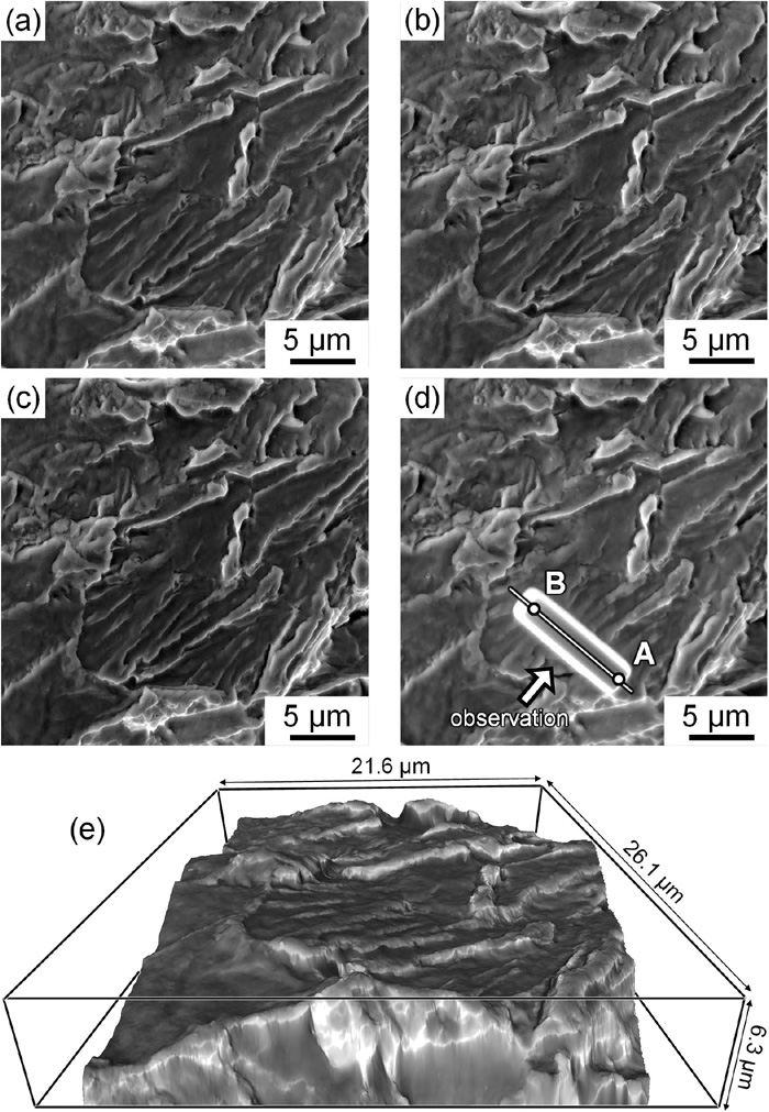
Figure 1 shows an optical microscopy image of the heat-treated specimen. The volume fraction of equiaxed ferrite grains was 87.4%. The average size of ferrite grains measured by line-interception method was 10.9 μm. High-angle grain boundaries of ferrite were the preferential initiation sites of cracks in hydrogen-related fracture and these cracks propagated in a transgranular manner, leading to quasi-cleavage fracture.10) As a result, most areas of the fracture surface (91.3%) in the hydrogen-charged specimen consisted of quasi-cleavage surfaces with serrated markings. Figures 2(a)–2(c) shows SEM images of a representative hydrogen-related quasi-cleavage fracture surface observed with tilting angles of 0°, +5°, and −5°, respectively. The reconstructed three-dimensional image of the corresponding area is presented in Fig. 2(e). A Pt layer was deposited to preserve the surface morphology (Fig. 2(d)), and then an STEM sample, whose observed plane was almost vertical to the serrated markings, was lifted out. Figure 3(a) is an enlarged view of Fig. 2, and the points A and B in Figs. 2(d) and 3(a) indicate the identical positions. Figure 3(b) shows an STEM image of the microstructure beneath the white solid line in Fig. 3(a). The observed area was inside one grain (Grain I). We can find that the serrated markings clearly correspond to the corners of step-like morphology of the fracture surface. Figure 3(c) is a schematic illustration of three-dimensional morphology of the quasi-cleavage fracture surface presented in Figs. 2 and 3. In order to clarify the crystallographic feature of the step-like morphology, we examined the orientation of microscopic facets indicated by white broken lines in Fig. 3(b). The normal direction of each facet in Fig. 3(b), i.e., facets 1–6, was determined from the crystallographic orientation obtained from the Kikuchi diffraction pattern, the cross-sectional shape of the fracture surface in the STEM image, and the inclination to depth direction of each facet estimated from the reconstructed three-dimensional image. Figure 3(d) shows a stereographic triangle on which the normal direction of each facet is plotted (the number of each pole corresponds to each fracture facet component in (b)). The results indicate that almost all the facets are nearly parallel to the {011} plane. Accordingly, it can be said that the hydrogen-related quasi-cleavage fracture surface exhibited a step-like morphology consisting of microscopic {011} facets. We previously reported that the hydrogen-related quasi-cleavage fracture surfaces were parallel to the {011} planes in more macroscopic scale.10) The present result demonstrated that the quasi-cleavage fracture surfaces macroscopically parallel to the {011} plane consisted of several microscopic {011} facets. Here, we defined the directions of serrated markings as the longitudinal direction of each microscopic {011} facet (Fig. 3(c)). As shown in Fig. 3(e), the directions of serrated markings in Grain I were almost parallel to <111> direction lying on the microscopic {011} facets (the number of each pole corresponds to each serrated marking in Fig. 3(a)). It should be noted that the Kikuchi diffraction patterns and the cross-sectional shape of the fracture surface used in the orientation analyses were obtained without tilting the sample in STEM, while the STEM image (Fig. 3(b)) was taken after tilting the sample a certain degree in order to acquire a clear contrast.


Figure 4 shows the analysis results on the hydrogen-related quasi-cleavage fracture in another grain (Grain II). In this case, the observed plane of the STEM sample was almost parallel to the serrated markings; (a, b) SEM images of the identical area before and after Pt deposition, (c) an enlarged view of (a), and (d) an STEM image of the microstructure beneath the white solid line in (c). The normal directions of the microscopic facets existed in Fig. 4(d) are plotted in (e). As well as the case shown in Fig. 3, almost all the quasi-cleavage facets were nearly parallel to the {011} plane, though some of them, particularly facet 2, were largely deviated from {011} plane. Unlike Grain I, the direction of serrated marking lying on the microscopic (011) facet in Grain II was [0.842 0.319 -0.434], nearly parallel to [21-1] direction (Fig. 4(f)).

In order to investigate the relationship between deformation microstructure, particularly dislocation cell structure, and serrated markings, we fabricated two STEM samples from the quasi-cleavage fracture surface in Grain III (Figs. 5(a), 5(b): before and after Pt deposition). The observed planes of the samples were almost vertical (Figs. 5(c)–5(e)) and parallel (Figs. 5(f)–5(h)) to the identical serrated marking. Figures 5(e), 5(h) are schematic illustrations of the dislocation cell structure in (d, g), respectively. Because the dislocation cell boundaries did not correspond to the serrated markings in both the samples, we concluded that the dislocation cell boundaries were not the origin of serrated markings.

We analyzed the hydrogen-related quasi-cleavage fracture surfaces of five grains in total and the results were summarized in Fig. 6. Almost all the microscopic quasi-cleavage facets were nearly parallel to the {011} plane (Fig. 6(a)). As shown in Fig. 6(b), the directions of serrated markings were nearly parallel to <110> direction in the grains other than Grain II, while it was nearly parallel to <112> direction in Grain II (star mark). We confirmed that these results shown in Figs. 6(a), 6(b) were not dependent on tensile directions because tensile directions of the observed grains were not specific as shown in Fig. 6(c).

In order to discuss the origin of microscopic {011} quasi-cleavage facets, we summarized the inclination angles of the {011} slip planes from the tensile axis (θSP-TA) and the largest Schmidt factor (Sf) for each six crystallographically equivalent {011} slip plane assuming the <111> {011} slip system (Table 1). The large θSP-TA means the large resolved normal stress imposed on the {011} plane. The six {011} slip planes are listed in the order of larger θSP-TA. The {011} plane parallel to the microscopic quasi-cleavage facets is highlighted by gray. It is obvious that the {011} planes with the largest θSP-TA correspond to the microscopic quasi-cleavage facets in all the grains other than Grain II. In Grain II, on the other hand, the observed microscopic quasi-cleavage facets are parallel to the {011} plane with the largest Sf, while its θSP-TA is the second largest. The difference between maximum and second θSP-TA is small (8.4°) in Grain II. Therefore, we infer that the resolved normal stress imposed on the {011} slip plane is an important factor for the hydrogen-related quasi-cleavage fracture, and that the hydrogen-related quasi-cleavage fracture is not directly resulted from hydrogen-enhanced slip deformation, such as slip plane decohesion.
Table 1. Summary of the inclination angles of the {011} slip planes from tensile axes (
θSP-TA) and the largest Schmidt factors (
Sf) for each six crystallographically equivalent {011} slip plane in the analyzed grains. The six {011} slip planes are listed with the order of larger
θSP-TA for each grain. The {011} plane parallel to the microscopic quasi-cleavage facets in each grain is highlighted by gray.
| No. | Grain I | Grain II | Grain III | Grain IV | Grain V |
|---|
| serrated markings// [1-10] | serrated markings// [2 1 -1] | serrated markings// [1-10] | serrated markings// [01-1] | serrated markings// [1-10] |
|---|
| {011} slip plane | θSP-TA | largest Sf [slip direction] | {011} slip plane | θSP-TA | largest Sf [slip direction] | {011} slip plane | θSP-TA | largest Sf [slip direction] | {011} slip plane | θSP-TA | largest Sf [slip direction] | {011} slip plane | θSP-TA | largest Sf [slip direction] |
|---|
| 1 | 110 | 76.4° | 0.202 [1-1-1] | 101 | 64.2° | 0.366 [-111] | 110 | 77.4° | 0.202 [1-1-1] | 011 | 68.8° | 0.335 [1-11] | 110 | 70.4° | 0.265 [-111] |
| 2 | 011 | 43.4° | 0.462 [11-1] | 011 | 55.8° | 0.435 [1-11] | 011 | 42.2° | 0.458 [11-1] | 101 | 50.5° | 0.480 [ -111] | 011 | 48.9° | 0.444 [-1-11] |
| 3 | 101 | 35.5° | 0.391 [11-1] | 110 | 35.8° | 0.308 [-11-1] | 101 | 36.0° | 0.400 [11-1] | 110 | 30.2° | 0.313 [-111] | 101 | 39.0° | 0.371 [-1-11] |
| 4 | 0-11 | 23.0° | 0.358 [111] | 0-11 | 18.4° | 0.298 [111] | 0-11 | 22.8° | 0.354 [111] | -101 | 25.5° | 0.387 [111] | 0-11 | 18.2° | 0.297 [111] |
| 5 | -101 | 16.5° | 0.260 [111] | -101 | 14.0° | 0.229 [111] | -101 | 17.7° | 0.277 [111] | 0-11 | 15.6° | 0.242 [111] | -101 | 10.9° | 0.179 [111] |
| 6 | -110 | 6.1° | 0.098 [111] | -110 | 4.2° | 0.069 [111] | -110 | 4.8° | 0.077 [111] | -110 | 9.3° | 0.145 [111] | -110 | 7.1° | 0.118 [111] |
Gray highlight: quasi-cleavage facet, θSP-TA: inclination angle of {011} slip plane from tensile axis, Sf: Schmidt factor
4. Discussion
It has been reported that the hydrogen-related quasi-cleavage fracture is closely linked to plastic deformation.10,11,12,13,14,15) However, the present study demonstrated that the hydrogen-related quasi-cleavage fracture is not directly resulted from hydrogen-enhanced slip deformation, such as slip plane decohesion, but the resolved normal stress imposed on the {011} slip plane is important for the hydrogen-related quasi-cleavage fracture. This is because the {011} plane selected as a microscopic fracture facet correspond not to the {011} plane with the largest Sf but to that with the largest θSP-TA (Table 1). We previously observed the deformation microstructure in a ferritic steel and clarified that (i) hydrogen increased the relative mobility of screw dislocation to edge dislocation, leading to the tangled dislocation morphology, (ii) hydrogen increased the screw dislocation density at the strain revel just before the start of crack propagation, and (iii) micro-cracks propagated discontinuously by void coalescence parallel to the {011} plane traces.16) We proposed, based on these results, that vacancies nucleated by jog-dragging of screw dislocations coalesced with each other, leading to the hydrogen-related quasi-cleavage fracture along the {011} slip planes. Matsumoto et al.17) performed first-principles calculations and reported that hydrogen increased the activation energy for vacancy diffusion, resulting in the reduced diffusivity of vacancies. They showed that vacancies nucleated by jog-dragging of screw dislocations remained at a high density in the vicinity of the slip planes. Neeraj et al.18) observed nanoscale dimples on the hydrogen-related quasi-cleavage fracture surface in a ferritic-pearlitic steel. These results are consistent with the idea that the vacancies nucleated by jog-dragging of screw dislocation played a key role on the fracture phenomenon. Accordingly, we can consider that the resolved normal stress imposed on the slip plane is important for the coalescence of vacancies/voids induced by hydrogen-enhanced plastic deformation. We also infer that the step-like morphology of the fracture surface was originated from the connection of discontinuous microscopic {011} facets, which is consistent with our previous work.16) However, in this research, we could not clarify the detailed formation mechanism of the segments connecting microscopic {011} facets, namely, relatively vertical segments of the step-like morphology.
As shown in Fig. 6, the directions of serrated markings were parallel to <110> direction in grains other than Grain II and parallel to <112> direction in Grain II. The direction of vacancy nucleation by jog-dragging of screw dislocation can be simply calculated from the vector product of slip plane normal and line vector of screw dislocation. In Grain II, (011) [1-11] slip system had the largest Sf (= 0.435) and the direction of vacancy nucleation was [21-1] which is almost parallel to the direction of serrated marking ([0.842 0.319 -0.434]) (Fig. 4(f)). This supports the idea that the directions of serrated markings have close relationship with the directions of vacancy lines nucleated by jog-dragging of screw dislocation. On the other hand, in grains other than Grain II, the microscopic quasi-cleavage facets were parallel to the {011} planes with the largest θSP-TA and the serrated markings were parallel to <110> direction. Because the direction of vacancy nucleation by jog-dragging of screw dislocation is <112>, we could not clarify the origin of serrated markings parallel to <110> direction. Clusterization behavior of the vacancies introduced by multiple slip systems would have an influence on the formation of the serrated markings parallel to <110> direction. Previous studies discussed the formation of vacancy clusters in hydrogen-charged iron. For example, Tateyama et al.19) reported that linear cluster parallel to <111> direction and planar clusters parallel to {011} or {001} plane were energetically favorable under the existence of hydrogen. Hayward et al.20) considered the surface energy reduction by hydrogen trapped on the cluster surface and reported that compact or spherical vacancy clusters were energetically preferred compared with planar or linear configurations. However, other factors, such as stress/strain around crack tip, hydrogen gas pressure inside the cluster, and vacancy diffusion behavior should be considered for understanding the formation mechanism of serrated markings parallel to <110> direction.
5. Conclusions
In this study, the microscopic three-dimensional morphology and crystallographic feature of the hydrogen-related quasi-cleavage fracture surface in a steel mainly composed of ferrite microstructure was investigated. The major conclusions are as follow;
(1) Serrated markings corresponded to the corners of step-like morphologies which consisted of microscopic {011} facets whose longitudinal directions were almost parallel to <110> or <112> direction.
(2) The microscopic {011} quasi-cleavage facets had the largest inclination angle from the tensile axis among six crystallographically equivalent {011} planes, suggesting that the resolved normal stress imposed on the {011} plane is an important factor for the hydrogen-related quasi-cleavage fracture.
(3) Not only the slip deformation enhanced by hydrogen but also the coalescence of vacancies/voids induced by hydrogen-enhanced plastic deformation should be considered for understanding the mechanism of hydrogen-related quasi-cleavage fracture along the {011} planes.
Acknowledgements
This study was financially supported by JSPS KAKENHI Grant Numbers JP19J21267, JP15H04158, JP19H02459, and JP20K21083, and the Elements Strategy Initiative for Structural Materials (ESISM) through the Ministry of Education, Culture, Sports, Science and Technology (MEXT), Japan.
References
- 1) A. Shibata, Y. Momotani, T. Murata, T. Matsuoka, M. Tsuboi and N. Tsuji: Mater. Sci. Technol., 33 (2017), 1524. https://doi.org/10.1080/02670836.2017.1312210
- 2) A. Shibata, T. Murata, H. Takahashi, T. Matsuoka and N. Tsuji: Metall. Mater. Trans. A, 46 (2015), 5685. https://doi.org/10.1007/s11661-015-3176-x
- 3) M. Yamaguchi, J. Kameda, K. Ebihara, M. Itakura and H. Kaburaki: Philos. Mag., 92 (2012), 1349. https://doi.org/10.1080/14786435.2011.645077
- 4) I. M. Robertson, P. Sofronis, A. Nagao, M. L. Martin, S. Wang, D. W. Gross and K. E. Nygren: Metall. Mater. Trans. A, 46 (2015), 2323. https://doi.org/10.1007/s11661-015-2836-1
- 5) S. P. Lynch: Acta Metall., 36 (1988), 2639. https://doi.org/10.1016/0001-6160(88)90113-7
- 6) A. Kimura and H. Kimura: Mater. Sci. Eng., 77 (1986), 75. https://doi.org/10.1016/0025-5416(86)90355-1
- 7) S. P. Trasatti, E. Sivieri and F. Mazza: Mater. Corros., 56 (2005), 111. https://doi.org/10.1002/maco.200403821
- 8) A. W. Thompson: Fatigue Fract. Eng. Mater. Struct., 19 (1996), 1307. https://doi.org/10.1111/j.1460-2695.1996.tb00168.x
- 9) A. Shibata, H. Takahashi and N. Tsuji: ISIJ Int., 52 (2012), 208. https://doi.org/10.2355/isijinternational.52.208
- 10) K. Okada, A. Shibata, Y. Takeda and N. Tsuji: Int. J. Hydrog. Energy, 43 (2018), 11298. https://doi.org/10.1016/j.ijhydene.2018.05.011
- 11) H. K. Birnbaum and P. Sofronis: Mater. Sci. Eng. A, 176 (1994), 191. https://doi.org/10.1016/0921-5093(94)90975-X
- 12) T. Tabata and H. K. Birnbaum: Scr. Metall., 18 (1984), 231.
- 13) M. Nagumo: ISIJ Int., 41 (2001), 590. https://doi.org/10.2355/isijinternational.41.590
- 14) M. Nagumo and H. Matsuda: Philos. Mag. A, 82 (2002), 3415. https://doi.org/10.1080/01418610208240452
- 15) M. L. Martin, J. A. Fenske, G. S. Liu, P. Sofronis and I. M. Robertson: Acta Mater., 59 (2011), 1601. https://doi.org/10.1016/j.actamat.2010.11.024
- 16) K. Okada, A. Shibata, W. Gong and N. Tsuji: Acta Mater., 225 (2022), 117549. https://doi.org/10.1016/j.actamat.2021.117549
- 17) R. Matsumoto, N. Nishiguchi, S. Taketomi and N. Miyazaki: J. Soc. Mater. Sci., Jpn., 63 (2014), 182. https://doi.org/10.2472/jsms.63.182
- 18) T. Neeraj, R. Srinivasan and J. Li: Acta Mater., 60 (2012), 5160. https://doi.org/10.1016/j.actamat.2012.06.014
- 19) Y. Tateyama and T. Ohno: Phys. Rev. B, 67 (2003), 174105. https://doi.org/10.1103/PhysRevB.67.174105
- 20) E. Hayward and C. C. Fu: Phys. Rev. B, 87 (2013), 174103. https://doi.org/10.1103/PhysRevB.87.174103