Abstract
In order to blend PF (pellet feed) or concentrates for 20 mass% in sinter mixture and to displace coke fines or anthracite to biomass for 25 mass% in BAR (Bonding Agent Rate), sinter packed bed has been designed in ISIJ Research workshop. Outline of the design is shown as below.
As designing, most important factor is permeability, and it has to be maintained even though fine materials as PF or concentrates is highly blended (20 mass%). For high permeability, GP [Green Pellet] granulated from fine materials, is placed in lower layer of raw materials packed bed. In the lower layer, mill scale and biomass char, which has characteristic of different oxidation or combustion temperature and rate compared to coke fine, are placed with coke fines for keeping high temperature (>1200°C), because GP needs longer sintering time due to large diameter. In addition, chemical composition of GP is low bacisity (1.5) and low CaO content for keeping its shape through restricting melt formation at sintering. Restricting melt formation has possibility of improving sinter quality (RI,RDI).
In this study, Effect of the packed bed mentioned above on sinter performance and quality has been confirmed by sintering simulator which has performance of continuous charging and igniting with moving pallet car.
The main results are shown as below.
1) Sintering speed and product yield are maintained at blending 20 mass% of PF. So, sinter productivity are also maintained.
2) Sinter reducibility (RI) has been improved in addition to maintaining sinter reduction disintegration index(RDI) because of low FeO and low SiO2 content and restricting secondary hematite formation as mineral of sinter.
3) Remaining object is recovering sinter strength (TI) at the condition of low CaO content in sinter.
1. Introduction
The current issues of the sintering process are the reduction of CO2 emissions from the sintering machine and the increase of fine powder in the sintering raw material.
For CO2 reduction, the direct method is replacing coke fine with low grade oxidized iron oxide and biomass. With replacement of coke fine with mill-scale, coke free operation was attempted at Nakayama Steel in the 1990s.1) The problem at that time were an high permeability of the sinter packed bed at sintering and an increase of unoxidized scale after sintering. Since then, research on improving permeability has progressed.2) Next, evaluation as for the replacement with biomass3,4) by sintering pot test has been reported and resulted in decrease of product yield. In recent years, research results5) have been reported in which pre-carbonization and increase of size is effective in maintaining product yield.
On the other hand, an increase of fine particles (<125 μm) in the sinter raw material causes decreasing productivity through increasing permeability resistance of the sinter packed bed. Therefore, in order to reduce permeability resistance, granulation technology for sinter raw materials was studied. Especially, a method of dividing the sintered raw material into two granulation lines (separating granulation6) and selective granulation7)) has been proposed. Here, the separating granulation6) is the granulation in the two lines individually, and then granulated materials are gathered on a conveyor and transported to a sintering machine. In addition, since the granulated products by the each line are mixed each other during transportation, the mixer is not used after gathering. On the other hand, selective granulation7) is granulation for a specific iron ore brand and then granulated materials are re-granulated with the rest raw materials. Here, iron ore containing a high Al2O3 component is selected as the specific brand, and the Al2O3 component is concentrated inside the final granulated particles (pseudo-particles). As a result, the Al2O3 reaction is suppressed at sintering, which leads to improve the reductive disintegration property. Both separating granulation and selective granulation are based on the technical concept of semi-pellets8) with two-layer structure aiming at uneven distribution of chemical components.
Furthermore, as a granulation technology that does not divide into two granulating systems, HPS (Hybrid Pelletized Sinter)9) is the reprehensive technology, in which all raw materials are granulated with a pan pelletizer. This technology uses 12 pan pelletizers to make all the fine raw materials into spherical green pellets, and after that the coke fine is adhered on the green pellet. In addition, a method of adding limestone or coke fine from the outlet side of the drum mixer and mixing for a short time is also aimed at adhering coke fine and lime stone on granules. These technology of producing granule adhered with limestone and coke fine might has same philosophy of semi-pellet.8)
The technical idea of semi-pellet with two-layer structure,8) which is the basis of these practical technologies, is that the coating layer of the granulated product is made into two layers, the inner layer has a non-molten composition, and the outer layer has a molten composition with high CaO concentration. As result, the molten portion can have high fluidity at a high temperature, the bonding strength of sintering can be increased, and calcium ferrite having good reducibility can be formed. Ideally, if the iron ore in the inner core is not melted and assimilated, it will not be accompanied by crystallization hematite, so that the reduction pulverization property will also be improved. Furthermore, because adding coke fine to granulated material has an effect for improving granulation, productivity is improved through increasing permeability of sinter packed bed.
Since 2000’s, the MEBIOS method10) has been proposed as an advanced form of separate granulation technology. As mentioned before, in separate granulation method, low CaO and high CaO pseudo-particles are existed. The feature of MEBIOS is that Low CaO pseudo-particles are further larger (called as green pellet [GP]) .In this method, as shown in Fig. 1,11) a low packing density region is formed at the boundary between the GP and the other pseudo-particles by the gas flow around the GP and the sintering reaction based on this gas flow. Moreover, sintering shrinkage degree is restricted by receiving downward load onto GP. As the result, gas flow resistance is decreased and high productivity is achieved. Conventionally, quicklime and some organic binders have been generally used as binders at granulation, but in recent years, using goethite crushed to μm scale or less as a binder has been developed.12) In addition, it was found that a dry particle is effective as a material for suppressing the sintering shrinkage, although particle size is small. Then, return fine was adopted as the dry particles by adding return fine after granulation.

Now, in this research, we focus on the MEBIOS method and examine effect of placing GP in the lower sintering layer on the sinter productivity and quality. From the viewpoint of permeability, it is advantageous to arrange the large particle placing the lower layer, but until now, there have been few studies specializing in the arrangement of designing the lower layer. In this study, the blending ratio of GP in the lower layer was designed based on the knowledge obtained by the study group. This will be explained in detail in Chapter 2. And in the sintering test, a large sintering simulator with a raw material weight of 1.3 tons was used to evaluate under the charging and ignition conditions similar to actual machine.
2. Design of Sinter Packed Bed Studied in ISIJ Research Group
2.1. Target Value at ISIJ Research Group
The target value for blending PF (pellet feed) and concentrate is 20 mass% in the raw materials as a response to resource deterioration, and the target value for blending carbon-neutral biomass charcoal in the carbon source is 25 mass% for reducing CO2 emissions.
2.2. Design of Sinter Packed Bed
Technical problem at increasing blending ratio of PF or concentrate is increase of permeability resistance in sinter packed bed. Negative influence by increase of permeability resistance has two key points. One is decrease of gas flow rate, which results in decreasing sintering rate. The other is uneven flow in sinter packed bed, which causes formation of unsintered portion and decreasing product yield.
For decreasing permeability resistance in sinter packed bed, placing GP at lower layer is effective as shown in Fig. 2. The reason is keeping low permeability for all sintering period from upper to lower sintering. In addition, more sintering time is necessary for GP. Therefore it is reasonable to place GP in lower part. Furthermore, if a plurality of Bonding Agent having different combustion temperatures and combustion rates are used in this lower layer, the high temperature keeping time is extended.

Here, it is desirable that the GP retains its shape even after sintering. Retaining shape is effective to suppressed sintering shrinkage, and as a result, permeability resistance during sintering keeps lower during whole sintering. In order to maintain the shape, it is necessary to suppress liquid phase formation in GP, and design chemical composition is low basicity (CaO/SiO2) and low CaO. However, if the basicity (CaO/SiO2) is too low, it is easy to generate silicates that are difficult to reduce in BF, so we designed the basicity (CaO/SiO2) to be 1.5, which is the lower limit value. In addition, the lower basicity of GP (CaO/SiO2) has an incidental effect. That is increasing the basicity in upper layer not containing GP. Since the upper layer with low yield and low strength, higher basicity (CaO/SiO2) has an effect of recovering them.
2.3. Target Value
(1) Blending Conditions and Design for GP
① Upper limit for blending ratio of fine iron ore in GP is 67 mass%, because a certain amount of coarse nuclear particles are required for granulation.
② GP component is designed to have a basicity of 1.5 and contains 1 mass% of coke fine. The aim is to maintain the shape (suppressing fluidization) and to suppress strength decrease during the sintering process.
③ GP blending ratio in the lower layer was designed to 50 mass%, mixed with the ordinary granulated materials (pseudo-particles). This is because it is difficult to secure strength by sintering GPs alone. And so, for countermeasure, the aim is to bond GBs each other with liquid phase generated from ordinary pseudo-particles at sintering.
(2) Ratio of Upper and Lower Layer
From upper limit value of PF blending ratio described in (1)① and appropriate blending value of GB described in (1)③, in order to satisfy the target value of PF blending ratio (20 mass%), the ratio of upper layer and lower layer was determined as 40 mass%: 60 mass%.
(3) GP Amount
From the upper limit described in (1)① above, in order to satisfy the study group target value of 20 mass% of fine powder, the GP production amount will be 30 mass% with respect to the new raw material.
(4) Charcoal Material Design
In order to place all the biomass charcoal in the lower layer and satisfy the 25 mass% of the total coal material for the biomass charcoal, which is the target value of the study group, the lower layer should have a biomass charcoal compounding ratio of 42 mass%.
In this study, PKS (Palm Kernel Shell) char obtained by carbonizing PKS was used as the biomass charcoal. PKS is a residue product during producing palm oil from coconut palm. Concretely, PKS is the remaining seed shells that are further squeezed the remaining seeds after first squeezing outside soft flesh fruit. This PKS is carbonized to obtain PKS char. In this study, PKS char was obtained by heat treatment using a rotary kiln under atmospheric circulation at a kiln outer wall temperature of 800°C. for 5 minutes.
3. Experimental Method
3.1. Test Case
The test cases are shown in Table 1.
Table 1. Experimental cases (mass%).
| ① Case 0 | ② Case 1 | ③ Case 2 |
|---|
| upper | lower | upper | lower | upper | lower |
|---|
| PF content | 0 | 0 | 20 | 20 | 0 | 33 |
| PKS char: coke fine | 0:100 | 0:100 | 25:75 | 25:75 | 0:100 | 42:58 |
| Mill scale content | 1.0 | 1.0 | 1.0 | 1.0 | 0 | 1.7 |
| GP content | – | – | – | – | – | 50 |
| PF content in GP | – | – | – | – | – | 67 |
| CaO/SiO2 in ordinary materials | 1.8 | 1.8 | 1.8 | 1.8 | 1.9 | 1.7 |
| CaO/SiO2 in GP | – | – | – | – | – | 1.5 |
① Case 0: Base (ordinary granulation)
1 mass% of scale was added to the new raw material without adding PF and PKS char. The basicity (CaO/SiO2) was 1.8. The same composition was designed for both the upper layer and the lower layer.
② Case 1: High blending ratio of PF (ordinary granulation)
The mixing ratio of PF was 20 mass% and ratio of PKS char and coke fine was 25:75. Blending ratio of scale was 1 mass%. The basicity (CaO/SiO2) was 1.8. The same composition was used for both the upper layer and the lower layer.
③ Case 2: High blending ratio of PF (separate granulation)
Designed under the conditions described in Chapter 2. As well as PKS char, mill scale was also blended only in the lower layer. Here, the Blending ratio of raw material in which the upper layer and the lower layer were combined was matched with Case 1.
3.2. Blending Conditions
Table 2 shows blending conditions for each case. In addition, the blending conditions of GP in Case 2 are also shown. In Case 0, the blended ore of the actual sintering machine was used, limestone was added as the flux, and coke fine and mill scale were added. Here, the amount of limestone is small because a certain amount of limestone is contained in the blended ore. In Case 1 and Case 2, as described above, 20 mass% of PF was blended and 25 mass% of coke fine was replaced with PKS char. Here, when substituting with PKS char, fixed carbon equivalent was used. For GP, quick lime was blended in 3 mass% (to GP weight) to strengthen granulation, and coke fine was blended in 1 mass% (to GP weight) to ensure the strength after sintering of GP. Brazilian pellet feed was used as the PF, and an Australian goethite was used as the sinter feed. Here, Case 1 and Case 2 have a constant composition in which the upper layer and the lower layer are combined.
Table 2. Blending conditions (mass%).
| ① Case 0 | ② Case 1 | ③ Case 2 |
|---|
| upper | lower | upper | lower | upper | lower | GP |
|---|
| Pre-Blending ores | 38.63 | 55.67 | 26.31 | 37.92 | 38.54 | 25.69 | |
| Geothite ore | | | 3.38 | 4.87 | | | 8.25(27.5) |
| Hematite PF | | | 8.2 | 11.8 | | | 20.0(66.7) |
| Mill scale | 0.41 | 0.59 | 0.41 | 0.59 | | 1.00 | |
| Lime stone | 0.41 | 0.59 | 0.75 | 1.08 | 0.77 | 0.52 | 0.54(1.8) |
| Quick lime | | | 0.37 | 0.53 | | | 0.90(3.0) |
| Coke fine | 1.52 | 2.18 | 1.13 | 1.64 | 1.49 | 0.99 | 0.30(1.0) |
| PKS char | | | 0.42 | 0.61 | | 1.03 | |
| GP | | | | | | 30.0 | |
| Total | 41 | 59 | 41 | 59 | 41 | 59 | 30.0(100) |
Table 3 shows chemical composition of raw materials in this study. PF has characteristic of high iron content and low SiO2 and Al2O3 content.
Table 3. Chemical compositions of raw materials (mass%).
| t-Fe | FeO | M-Fe | CaO | SiO2 | Al2O3 | MgO | LOI |
|---|
| Pre-Blending ores | 53.13 | 3.19 | – | 8.04 | 4.28 | 1.43 | 0.74 | 8.98 |
| Geothite ore | 58.64 | 0.09 | – | 0.06 | 4.39 | 1.58 | 0.08 | 10.2 |
| Hematite PF | 67.26 | 0.16 | – | 0.01 | 2.00 | 0.64 | 0.0 | 0.37 |
| Mill scale | 74.15 | 65.9 | 3.98 | 0.83 | 0.59 | 0.21 | 0.05 | – |
| Lime stone | – | – | – | 55.1 | 0.14 | 0.03 | 0.35 | 44.0 |
Table 4 shows chemical composition as for sinter based on the blending design. For Case 0 it was standard as commercial sinter at 2019. For Case 1, it was low SiO2 and CaO content by high blending ratio of the Brazilian PF. Chemical composition of upper layer was the same as that of the lower layer. On the other hand, for Case 2, difference of chemical composition between upper and lower layer was large, since GP was placed at only lower layer. In addition, SiO2 and CaO content was higher in upper layer and lower in lower layer, compared with Case 0. This SiO2 content in lower layer is lower than that of performance data at commercial plant of HPS (Hybrid pelletized Sinter) process.
Table 4. Design of chemical compositions after sintering (mass%).
| ① Case 0 | ② Case 1 | ③ Case 2 |
|---|
| upper (40%) | lower (60%) | upper (40%) | lower (60%) | upper (40%) | lower (60%) | (GP) |
|---|
| T-Fe | 57.84 | 57.84 | 58.98 | 58.98 | 57.33 | 59.94 | 63.99 |
| CaO | 9.26 | 9.26 | 7.87 | 7.87 | 9.86 | 6.59 | 4.21 |
| SiO2 | 5.17 | 5.17 | 4.32 | 4.32 | 5.19 | 3.78 | 2.81 |
| Al2O3 | 1.54 | 1.54 | 1.31 | 1.31 | 1.54 | 1.16 | 0.90 |
| MgO | 0.80 | 0.80 | 0.54 | 0.54 | 0.81 | 0.37 | 0.03 |
| CaO/SiO2 | 1.79 | 1.79 | 1.82 | 1.82 | 1.90 | 1.74 | 1.50 |
Raw materials for GP were mixed with water for 1 minute with a high-speed agitating mixer in batch. Here, water content in mixture was 9.0 mass%. After the high-speed agitating mixer treatment, the mixtures was granulated by continuously charging into and continuously discharging out of a pan pelletizer. The pseudo-particles after granulation which was granulated product was sieved and sized to 5–20 mm were called as “GP”. As shown in Table 5, the size distribution was grasped by weighing each particle size category after sieving.
Table 5. Size distribution of green pellet (GP).
| size (mm) | 5–10 | 10–15 | 15–20 |
| occupation (mass%) | 45.2 | 24.7 | 30.1 |
The materials were mixed without adding water for 4 minutes, then mixed with water addition for 1 minute and mixed for another 3 minutes after water addition. However, in Case 2, only PKS char was added after the drum mixer granulation mentioned above.
3.4. Charging and Sintering
3.4.1. Equipment Apparatus
Sintering simulator can charge and ignite while transferring pallets in the same way as the commercial sinter machine. After ignition, the pallets are transferred to a predetermined WB (Wind Box) and sintered in a stationary state. Here, the dimensions of the pallet are 400 mm of width and 800 mm of machine length, and 750 mm of height. By connecting 4 pallet, the machine length is 3200 mm. The first and last pallets of the four pallets have heat loss, and the sintering performance is evaluated with the second pallet from the beginning. Therefore, temperature measurement, air volume measurement, and gas analysis are performed on this pallet. Since 350 kg of sinter cake can be obtained per a pallet, it is possible to evaluate the sinter quality by dividing it into 5 parts by the layer along vertical direction.
3.4.2. Charging
First, sinter for hearth layer was laid on the pallet so that the layer height was 40 mm.
Next, the lower layer raw material was charged. For the lower layer, a method was used in which particle size segregation was not applied as much as possible. Specifically, a certain amount of raw material was charged in a stationary state without moving the sintering pallet at 60° angle vertically from horizontal line for certain time. After stopping charging, the sintering pallet was transferred by 400 mm and stopped, and the raw materials were charged again. This procedure was repeated. At this stage, the piles of raw materials were arranged at equal intervals in the pallet machine length direction, and the raw material layer heights were uneven in both the machine length direction and the width direction. Therefore, the raw materials were evened out by manually leveling them.
Finally, the upper layer raw material was charged. The upper layer raw material was continuously supplied by a method of subjecting particle size segregation. Specifically, the sintering pallet was returned to the starting point of mine supply and the sintering pallet was transferred and mine was supplied. The charging device was a distributed type with vertical slit ISF (Intensified Sifting Feeder),13) and the charging angle was 45°. The mining gate width, roll feeder rotation speed and pallet speed were adjusted so that the layer thickness was 280 mm.
3.4.3. Sintering
The ignition furnace was 800 mm in the length direction and passed pallet at the speed of 1.15 m/min at igniting sinter material in it. LPG was used as the ignition fuel, and the consumption amount was 10 Nm3/h. with an excess air ratio of 1.2. The sintering was finished at 3 minutes after the latest peak time of the exhaust gas temperature measured by the thermocouples (4 in total) placed in the WB directly under the 2nd and 3rd pallet from the top of the pallet. The sintering time was from the time when the central part of the 2nd pallet reached the central part of the ignition furnace, to from the latest peak time described above. The temperature inside the sintering layer was measured by providing three temperature measuring holes in the vertical direction at the center of the 2nd pallet machine length direction, inserting an Al2O3 protective tube to the center in the pallet width direction, and setting an R type of thermocouple in the protective tube.
After cooling for 30 minutes after sintering, the sinter cake in the 2nd pallet side was used as a sample for evaluating sinter yield and sinter properties, and the sample was divided into 5 parts in the vertical direction with a breaker to prepare a stratified sample. The sinter cake after crushing the breaker was dropped four times from a height of 2 m with a shutter tester and sinter products of over 5 mm was defined as sinter products.
3.5. Evaluation Items
Permeability of sinter packed bed, sintering speed, and product yield related to sintering productivity were evaluated. The permeability was evaluated as a JPU value, by measuring the air flow rate with a hot wire anemometer at a suction pressure of 15.0 kPa, on predetermined WB after charging the lower and upper layers of sinter mixture. The sintering speed was evaluated by the flame front speed (FFS) and burn through speed (BTS).
For sinter qualities, sinter strength (TI), reducibility (RI) and reductive disintegration (RDI) were measured in each layer divided for 5 part in height direction. For TI, 15 kg of sinter was recovered from the 10 mm to 40 mm diameter sinter sieved after evaluating the product yield. Tumble index is the ratio of 5 mm or more after treated with a TI test drum at 20 rpm for 10 minutes. For obtaining sinter for RDI and RI , the rest sinter after TI test and crushed sinter from 40 mm diameter and over sample with a jaw crusher were sieved to 15–20 mm and 19–21 mm diameter, respectively. Here, as for the lower layer sample of Case 2, there were GP-derived sinter and other sinter particles, but they were randomly selected. Most sinters had a form in which the GP-derived part and the other parts were combined. There were some samples in which GP-containing in sinter was broken.
As a further consideration, the microstructure observation, EPMA and pore characteristics before and after sintering were evaluated.
4. Experimental Results
4.1. Permeability and Sintering Speed
Figure 3 shows permeability of sinter packed bed, sintering speed and sintering time. Blending GP has a great effect on increasing permeability of sinter packed bed before sintering. Compared with the permeability before sintering, the effect of improving the sintering speed is small. As a result, the decreasing sintering time was a little (58.1⇒49.0 minutes) only to recover from the increase of sintering time (48.1⇒58.1 minutes) caused by increasing PF blending ratio.
Figure 4 shows the transition of flame front obtained from the temperature information of each layer. In the blending GP case (□) of Case 2, flame front speed accelerates in the lower layer where GP is concentrated. As a result, it approaches Case 0 at the lowest layer position.

The state in which the coke fine or PKS char is burning in the sintering layer can be considered to be longer from the starting temperature increasing time to the maximum temperature time in the layer. and this period is referred to as combustion time. Figure 5 shows the distribution of the combustion time in the vertical direction of the sintering layer. In the blending GP case of Case 2, the combustion time became longer in the lower layer, despite the acceleration of the frame front speed. This is due to the delay in burning the coke fine mixed in the GP, and the difference in the combustion speed of the coke fine and PKS char placed in the lower layer. A mill scale was also placed in this lower layer, and it is considered that the oxidation reaction also affected the temperature profile. The extension of the combustion time is effective in sintering GP with a large particle size well. However, the increasing the combustion time is considered to be the reason why the degree of shortage sintering time decrease with respect to the degree of increasing permeability (JPU) before sintering shown in Fig. 3.

Figure 6 shows sinter productivity and product yield. Although the productivity was reduced by 17% by adding 20 mass% of PF (27.4⇒22.7 t/d/m2; comparison between Case 0 and Case1), the productivity was recovered by separate granulation (comparison between 22.7⇒27.0 t/d/m2 Case 1 and Case 2) was also obtained.
Product yield was high in Case 1. This is considered to be due to the decreasing sintering speed. Product yield of Case 2 had a difference of 0.1% from that of Case 0, which was almost the same value. As shown in Fig. 3, Case 2 has the same sintering time as Case 0, but as shown in Table 4, it has a low CaO of 1.4% (9.26; Case 0, 7.87; Case 1, Case 2), it is evaluated that sinter layer design of Case2 is effective for higher product yield.
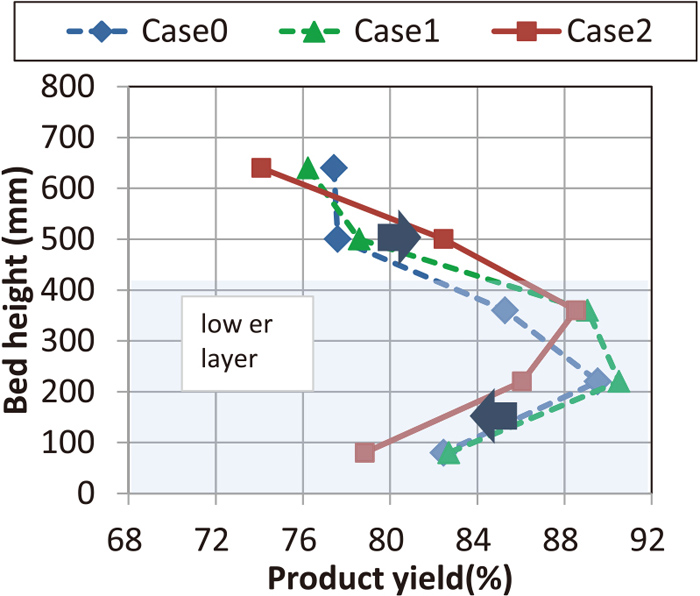
Figure 7 shows the product yield distribution in the layer for vertical direction. In Case 2, it increased in the second upper layer and decreased in the lower layer. The former was due to high CaO concentration and high basicity (CaO/SiO2) of sinter composition, and the latter was due to low CaO low basicity (CaO/SiO2) of sinter composition, but even GP with a diameter of 5–20 mm did not cause a significant decrease of product yield. Figure 8 shows the sintered cake in the lower layer of Case 2, and it can be seen that even a coarse GP turns silver color which shows sintering enough.
Figures 9 and 10 show distribution for the maximum temperature and high temperature keeping time in sintering layer in vertical direction. In Case 2, at the lower layer (GP layer) the maximum temperature and the high temperature keeping time of more than 1200°C decreased. In other cases, as shown in Fig. 10, the lower the layer, the longer the high temperature keeping time. Despite the extension of the combustion time shown in Fig. 5, the high temperature keeping time was shortened. This shortage was caused by decreasing maximum temperature.
4.3. Sinter Quality
4.3.1. Outline
Figure 11 shows sinter strength, reducibility and reductive disintegration.
Regarding the sinter strength, Case 1 and 2 were lower than Case 0. This is considered to be the effect of a significant decrease of CaO component. However, sinter strength for Case 2 was higher than that for Case 1. It is considered that this is because the CaO component of the raw materials except GP was enough high to generate much melt for strong bonding. And strength of GP portion was enough however the melting was suppressed.
Regarding the sinter reducibility, Case 1 was higher than Case 0. This is considered to be the effect of lowering SiO2. Case 2 was higher than Case 1. Because SiO2 of the raw materials except GP is higher than that of Case 0 and 1, it is considered that the reducibility of the GP part was significant high.
Regarding the sinter reductive disintegration, Case 1 had a higher than Case 0. This is considered to be the effect of lowering SiO2 content. However, Case 2 had almost the same value as Case 0 even though SiO2 content of Case 2 were the same as Case 1 and lower than Case 0. In details, SiO2 content in raw materials except GP was higher and that in raw materials of GP was lower compared with Case 1. And so, there are certain factors that suppress reductive disintegration in sinter from GP, which will be discussed in Chapter 5.
4.3.2. Sinter Strength
Figure 12 shows the sinter strength (TI) distribution in the bed vertical direction of the sinter layer. TI for Case 2 increased in the upper layer and decreased in the lower layer. As well as the product yield, these results were considered to be caused by high CaO content and high basicity (CaO/SiO2) in upper layer, and by low CaO low basicity (CaO/SiO2) content in lower layer.

Figure 13 shows the relationship between the high temperature keeping time and the sinter strength. The sinter strength increased with the increase in the high temperature keeping time. Since the upper part in sinter layer has an extremely short high temperature keeping time, the sinter strength is extremely low. As for high sinter strength for Case 2 at top zone was caused by not only high-temperature keeping time, but also high basicity (CaO/SiO2). Specifically, a high temperature keeping time for the four points (■) except the top layer are around 6 minutes, but the sinter strength of the upper second layer was higher than the other two points. Since GP has a low CaO low basicity (CaO/SiO2) composition and a high sintering speed, the sinter strength was low, but the strength has not been fatally reduced.
4.3.3. Sinter Reducibility and Reductive Disintegration
Figure 14 shows the distribution of FeO content in sinter in the vertical direction of the sintering layer. In each case, FeO was extremely high in the uppermost layer. On the other hand, the lower layer in the case of Case 2 containing GP indicated low FeO content. In the lower layer of Case 1, FeO was further higher than that in the lower layer of Case 0. In both cases, GP was not added, but as shown in Fig. 8, the maximum temperature of the lower layer was higher in Case 1 than in Case 0. Therefore, it is considered that more magnetite has crystallized. Here, it is considered that the higher maximum temperature is caused by lower sintering speed.
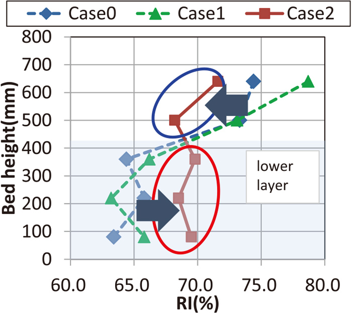
Figure 15 shows the distribution of RI in the vertical direction of the sintering layer. Generally, the upper layer of the layer has a high RI (%) due to high porosity. However, for Case 2, RI decreased in the upper layer and increased in the lower layer, resulting in almost equal value from the upper layer to the lower layer.
Figure 16 shows the distribution of RDI in the vertical direction of the sintering layer. For Case 2, the RDI decreased in the lower layer where GP was placed.
Figure 17 shows the relationship between FeO in sinter and RI. Common to all cases, the top layer showed high FeO but high RI. For the three points from the middle layer to the lower layer, negative relationship between RI and FeO has confirmed, and lower layer of Case 2 where GP was placed showed externally low FeO and high RI.
Figure 18 shows the relationship between FeO in sinter and RDI. The uppermost layer showed high FeO but high RDI. Common to all cases, at the three points from the middle layer to the lower layer, negative relationship between RI and FeO has confirmed, and lower layer of Case 2 showed low FeO but low RDI. It is presumed that it suppresses the formation of secondary hematite.
From Figs. 16 and 17, regarding the peculiarity of the sinter in the uppermost layer, FeO increases due to the low oxygen concentration at the time of ignition and the high content of coke fine, but the high temperature keeping time is short and the load from above is little. And so porous low-strength sinter with large irregularities is formed. As a result, the reducibility is improved, but the reductive disintegration is poor due to low strength. On the other hand, decreasing RI at top zone of Case 2 is considered to be due to decreasing pores caused by high basicity (CaO/SiO2) and high CaO.
5. Discussion
In this study, the GP layer for Case2 showed a reducibility improvement due to lowering FeO. In addition, RDI was also improved. In the viewpoint of pore and mineral texture, improvement of both RI and RDI was considered.
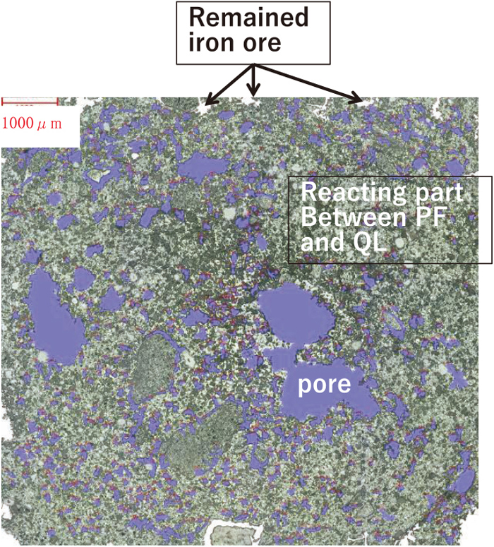
Figures 19 and 20 show optical micrographs of GP cross sections before and after sintering respectively. In the GP before sintering, macro voids of about 1 mm to 2 mm diameter were observed around coarse particle of several mm diameter. Small voids were found in the parts where the fine powders were in contact with each other. The fine particles were mainly composed of PF and quicklime.
After sintering, GP did not fluidize and maintained its shape. Therefore, a large amount of liquid phase is not generated. This is because the basicity (CaO/SiO2) is 1.5 and the CaO concentration is as low as 4.22 mass% (SiO2 is 2.81 mass%). Pore after sintering was larger than the voids between the fine particles before sintering. It is considered that pore formation occurred due to the reaction between fine particles and the integration of voids in a narrow region of about 1 mm due to low liquid phase. In addition, white particles were observed, which are considered to be unreacted iron ore.
Figure 21 shows the pore size distribution of sintered GP collected from the second layer from the bottom layer of Case 2 (fourth layer from the upper stage side). For comparison, results for sinter of Case 1 from the same height was shown. Here, the pore diameter was evaluated by the image analysis method in the field of view of 67.4 mm2 of the sample cross section.
The characteristics of the pore size for the sintered GP were that the number of pores exceeding 100 μm was small and the number of pores of 40 μm or less was large.
Here, the reactive area at the reduction was smaller in sintered GP because the total number of pores is almost same (GP: 687, sinter (Case 1): 708) and pore size was smaller. Therefore, GP acts on the suppressive side in terms of reducibility. Therefore, it was clarified that the improvement of the reducibility of the GP layer shown in Fig. 15 was not able to be explained in the view point of pore size and number. As shown in Fig. 16, the main factor is considered to be the influence of chemical components and forming minerals, mainly FeO decrease in sinter.
Next, we consider the forming minerals.
Figures 22 and 23 show SEM images before and after sintering. Each was the observation images at 4 levels (magnified to 40, 100, 400, 1000 times). Furthermore, Figs. 24 and 25 show the major element mapping by EPMA images (magnified to 1000 times).
Regarding GP before sintering, it can be seen from the 40x image that it is composed of granulated fine particles containing coarse particles. From 1000x image , the strip-shaped texture having a high Fe concentration and the gap are filled with the Ca-containing texture. The former is fine ore and the latter is quicklime.
For the sintered GP, the bonds of solid particles and pores (resin) between solid particles were observed from the 40x image. And from 1000x image, different textures coexisting in the particles were observed. From EPMA, there were two types of mineral texture were confirmed. One was a texture which has high Fe composition and does not contain either Ca or Si, and the other was a texture which has Fe, Ca and a small amount of Si. The former texture is considered to be primary hematite because the ore shape is maintained except the rounded corners. The latter surrounding primary hematite particles is considered to be calcium ferrite.
Comparing the structures before and after sintering, it is considered that iron ion diffused into the quicklime, and as the result, calcium ferrite was formed. Further, since the shape of iron oxide is similar before and after sintering, it is considered that the generation and movement of the liquid phase are not so much. Furthermore, little secondary hematite was observed, which is thought to be due to the limited liquid formation and assimilation. It is considered that RDI improved even at low FeO due to the suppression of secondary hematite formation.
6. Conclusion
In order to blend PF or concentrates for 20 mass% in sinter mixture and to displace coke fines to biomass char (PKS char) for 25 mass% in BAR(Bonding Agent Rate), sinter packed bed has been designed in ISIJ Research workshop. Specifically, the effectiveness of designing sinter packed bed where low slag GP (green pellets) that has been granulated from PF, PKS char which has a high-speed combustion property, and scales placed in the lower layer, was examined by a sintering simulator with a raw material of 1.3 tons. The major results are shown as bellows.
(1) Productivity was maintained even when 20 mass% of PF was blended. This is the effect of enlarging granulation size (GP).
(2) Even if 25 mass% of PKS char that has a high-speed combustion property was replaced, the product yield was maintained. This is the effect of using coke fine and mill scale, which has a slower combustion/oxidation rate, with PKS char in the lower layer.
(3) The sinter strength was weaker due to lowering the CaO concentration of sinter.
(4) The reducibility was improved while maintaining the sinter reductive disintegration. It is considered that the low SiO2 and low FeO content has a role of improving reducibility and that the secondary hematite crystallization is suppressed by suppressing GP melting.
References
- 1) M. Nakano, T. Yamakawa, N. Hayakawa and M. Nagabuchi: ISIJ Int., 38 (1998), 16. https://doi.org/10.2355/isijinternational.38.16
- 2) K. Fujino, T. Murakami and E. Kasai: Tetsu-to-Hagané, 100 (2014), 160 (in Japanese). https://doi.org/10.2355/tetsutohagane.100.160
- 3) M. Zandi, M. Martinez-Pacheco and T. Fray: Miner. Eng., 23 (2010), 1139.
- 4) R. Lovel, K. Vining and M. Dell’Amico: Miner. Process. Extr. Metall., 116 (2007), 85.
- 5) T. Kawaguchi and M. Hara: ISIJ Int., 53 (2013), 1599. https://doi.org/10.2355/isijinternational.53.1599
- 6) T. Kawaguchi, S. Sato and K. Takata: Tetsu-to-Hagané, 73 (1987), 1940 (in Japanese). https://doi.org/10.2355/tetsutohagane1955.73.15_1940
- 7) T. Haga, A. Ohshio, Y. Hida, H. Fukuda and N. Ogata: Tetsu-to-Hagané, 83 (1997), 233 (in Japanese). https://doi.org/10.2355/tetsutohagane1955.83.4_233
- 8) E. Kasai, I. Shu, S. Kobayashi and Y. Omori: Tetsu-to-Hagané, 70 (1984), 520 (in Japanese). https://doi.org/10.2355/tetsutohagane1955.70.6_520
- 9) N. Sakamoto, H. Fukuyo, Y. Iwata and T. Miyashita: Tetsu-to-Hagané, 70 (1984), 504 (in Japanese). https://doi.org/10.2355/tetsutohagane1955.70.6_504
- 10) E. Kasai, S. Komarov, K. Nushiro and M. Nakano: ISIJ Int., 45 (2005), 538. https://doi.org/10.2355/isijinternational.45.538
- 11) C. Kamijo, M. Matsumura and T. Kawaguchi: ISIJ Int., 45 (2005), 544. https://doi.org/10.2355/isijinternational.45.544
- 12) Y. Yamaguchi, M. Hara, H. Umemoto, Y. Morita, S. Teraji and M. Matsumura: Nippon Steel Tech. Rep., (2019), No. 413, 34 (in Japanese).
- 13) T. Inazumi, M. Fujimoto, S. Kasama and K. Sato: Tetsu-to-Hagané, 77 (1991), 63 (in Japanese). https://doi.org/10.2355/tetsutohagane1955.77.1_63