Regular Article
Influence of Initial Crystal Orientation and Carbon Content on Rolling-induced Texture in 3 Mass% Si Steel
2022 Volume 62 Issue 11 Pages 2382-2388

Details
2022 Volume 62 Issue 11 Pages 2382-2388
The influence of the initial crystal orientation and carbon content on rolling-induced texture was investigated using quasi-single crystals of 3.2 mass% Si steel. These specimens had {110}<001> and {110}<113> crystal orientations, which are common near surface textures for hot-rolled steel band. In the case of ultralow-carbon specimens, the initial {110}<001> orientation rotated to {111}<112> after 66% reduction cold rolling and the initial {110}<113> orientation rotated to near {211}<124>. It is considered that the crystal rotation from {110}<113> to near {211}<124> is caused by activation of the {110} slip system, which has the second largest Schmid factor. The {211}<124> orientation is not considered to be a stable rolling-induced texture; however, the {211}<124> orientation was well developed in the present experiments. In addition, the {211}<124> orientation has a geometric characteristic that if it rotates by activation of one slip system, it will revert to the initial {211}<124> crystal orientation by activation of another slip system. In the case of specimens containing carbon, the {110}<001> orientation rotated to {111}<112> and {100}<011> due to deformation twinning. On the other hand, the {110}<113> orientation rotated from the {211}<113> orientation to the {111}<112> orientation during cold rolling. Deformation twinning was also observed. It is considered that the crystal orientation of the deformation twins rotated to near {111}<112> by activation of the {110} slip system.
Electrical steel sheets are widely used as soft magnetic materials that contain silicon at several mass percent to improve the magnetic properties. In addition, better magnetic properties have been obtained by texture control to align the easy axis of magnetization, the <001> crystal direction in sheet planes. For example, almost all grains in grain-oriented electrical steel sheets have a {110}<001> orientation. There are some reports1,2,3,4,5) that the strong {110}<001> texture of grain-oriented electrical steel sheets, which is formed by secondary recrystallization, originates from near surface regions of hot-rolled steel sheets. It is generally known that the texture of hot-rolled sheets changes in the thickness direction from the surface, where the effect of rolling friction is large, to the center, which is mostly deformed by simple compression. The {110} crystal plane orientation near the surface is especially enhanced in regions strongly affected by shear deformation.4,5,6,7,8,9)
In a hot rolling experiment using 3 mass% Si steel, it was found that the near surface has a {110}<001> texture and the texture rotated around the normal direction (ND) from {110}<001>.8) The {110}<001> texture formed near the surface by hot rolling is not stable during cold rolling with a small shear component; therefore, crystal rotation occurs from {110}<001> during cold rolling. According to experiments using single crystals, it is known that a texture with an initial crystal orientation of {110}<001> rotates to {111}<112> by cold rolling and becomes {110}<001> again by subsequent recrystallization annealing.10,11,12,13,14,15,16,17,18,19,20) There are some reports that discuss why the {110}<001> orientation reappears after recrystallization annealing. One reason is that {110}<001> recrystallization nuclei form in the shear bands of the cold-rolled crystal structure.13,14,15) Another reason is that the initial crystal orientation remains in transition bands.16) The {110}<001> texture formed by hot rolling is inherited during cold rolling and subsequent recrystallization annealing. Therefore, it is considered that the inherited {110}<001> orientation becomes the nucleus of secondary recrystallization, i.e., the mechanism of structure memory.1,2,3,4,5)
However, the texture formed by hot rolling is not only {110}<001> as described so far, but also {110}<uvw> rotating about the ND axis; therefore, experiments on the texture formation process using the {110}<uvw> crystal orientation would be of interest. Experiments where {110}<229> and {110}<112> were used as initial crystal orientations were conducted for steel containing less than 3.1 mass% Si, and it was reported that the texture formed after rolling was different, although the initial crystal orientations were relatively similar.21) On the other hand, it is known that the carbon content in steel affects texture formation during cold rolling. Konishi et al.20) studied the effect of heat treatment on the texture of rolled low-carbon steel sheets with initial crystal orientations such as {110}<001> and {001}<110> by changing the state of carbide precipitation. Iida et al.22) investigated rolled polycrystalline 3.3 mass% Si steel with fine carbides and demonstrated a complicated internal structure with entangled dislocations. The present authors17) reported experiments using quasi-single crystals of 3.2 mass% Si steel with an initial crystal orientation of {110}<001>, with a carbon content of either 11 or 210 mass ppm. With cold rolling, deformation twinning tended to occur in specimens containing 210 ppm carbon. Twins were produced during the initial stage of cold rolling of the {110}<001> crystal, and the crystal orientation in the twins was close to {411}<122>, because of the Σ3 correspondence between the original crystal orientation and the twins. Subsequent rolling caused the texture to rotate to near {100}<011>, which is a stable rolling-induced texture.17,18) After subsequent rolling, the near {100}<011> texture due to twins was preserved as a stable crystal orientation after rolling with a 66% reduction ratio.
In the production process of grain-oriented electrical steel sheets, it is necessary to investigate texture formation in the presence of carbon because cold rolling is typically performed with steel containing carbon. However, few studies have investigated the formation of rolling-induced texture in the presence of carbon using an initial crystal orientation of {110} in the sheet plane, which is found in the near surface regions of hot-rolled sheets.19) Therefore, this article deals with cold-rolling-induced texture formation using quasi-single crystals of 3 mass% Si steel with a change in both the initial crystal orientation and the carbon content.
As exemplified in the texture near sheet surfaces in hot-rolled and annealed 3.2 mass% Si steel shown in Fig. 1, which was obtained prior to the experiment, the texture components are distributed in an area rotated about the ND from {110}<001> as reported by Matsuoka,8) and the relatively high-intensity region around {110}<113> is rotated by 25° around the ND from {110}<001>. Therefore, we focused on an initial {110}<113> orientation during cold rolling and compared the results with those for rolling-induced texture formation with an initial {110}<001> orientation.

Example texture of the near surface of hot-rolled and annealed steel sheet containing 3.2 mass% Si (ODF: φ2 = 45° section).
It is desirable to use a single-crystal sample to evaluate the effects of the initial crystal orientation and carbon content of steel, and to eliminate the effects of grain boundaries, in order to investigate texture formation. Therefore, a coarse-grained material obtained by secondary recrystallization was used in the present experiments. This material contains 3.2 mass% Si and has a thickness of 0.3 mm with a grain size of approximately 20 mm. A crystal misorientation of 3° or less from {110}<001> was achieved by secondary recrystallization.5)
Four specimens were prepared, as shown in Fig. 2. Specimens A-1 and A-2 were cut so that the <001> direction was parallel to the rolling direction (RD), and specimens B-1 and B-2 were cut so that the <001> direction was inclined 25° to the RD. Specimens A-2 and B-2 were carburized to produce different carbon contents; the chemical compositions of the specimens before and after carburization are shown in Table 1. All specimens were heated to 900°C in a dry N2 atmosphere and water cooled at a cooling rate of more than 40°C/s to ensure a solid solution of carbon in accordance with the literature.23,24)

Schematic diagrams of specimens with initial crystal orientations of {110}<001> and {110}<113>.
| Si | Mn | C | |||
|---|---|---|---|---|---|
| Specimen A | A-1 | 3.2 | 0.05 | 0.001 | Base |
| A-2 | 0.021 | Carburized | |||
| Specimen B | B-1 | 0.001 | Base | ||
| B-2 | 0.019 | Carburized |
Figure 3 shows scanning electron microscopy (SEM) longitudinal cross-sections of the specimens. Extremely fine precipitates were observed in the carburized samples. The precipitates observed in A-2 were presumed to be carbides because there was no difference between A-1 and A-2 except for the carbon content. Although carbon in steel is not completely soluble, it is considered that most of the carbon was present as a solute, because the carbide precipitates were very fine and few in number. Similar precipitates were also found in small amounts in B-2, although not as clearly as in A-2. It is considered that a small fraction of the carbides can be classified as ε carbide, although the structure of the precipitates could not be clearly determined.25) The difference in the appearance of the carbides between A-2 and B-2 could be due to the degree of etching during sample preparation. To confirm that the precipitates were carbides, some of the materials was aged at 400°C for 5 min, and SEM observations were performed again.

SEM images of longitudinal cross sections of secondary recrystallized grains in base and carburized specimens.
Figure 4 shows SEM images of the carburized A-2 and B-2 specimens, where coarsening in the direction parallel to <110> or <100> was evident in the respective specimens, and the precipitates were characteristic of carbides. Carbides were uniformly precipitated throughout the plate thickness; therefore, it is considered that the concentration gradient in the plate thickness direction that was formed during the carburization treatment was almost homogenized by solution treatment at 900°C. On the other hand, there was no change in carbide precipitates after aging treatment for the carburized specimens. These specimens were then cold-rolled with 66% reduction at room temperature, and the microstructure after rolling was observed using electron backscatter diffraction (EBSD; S-4300, Hitachi equipped with orientation imaging microscopy (OIM) analysisTM system, TSL Co.). The measurements were conducted at the center of an elongated crystal grain that appeared to be unaffected by the presence of grain boundaries. The rolling-induced texture was evaluated using X-ray diffraction. The X-ray radiation was focused to irradiate only a single crystal grain, although in some cases 2 to 3 crystal grains were included. {100}, {110} and {211} pole figures were obtained, and the orientation distribution function (ODF) was then determined.26) When determining the ODF, the rolling symmetry for the sample is already considered; therefore, the {100} pole figure used in the calculation is shown along with the ODF to indicate the crystal orientation without consideration of the sample symmetry.

SEM images of longitudinal cross sections of specimens after aging at 400°C for 5 min.
Figure 5 shows the ODF (Bunge representation φ2 = 45° cross-section) after rolling of specimens A-1 and B-1 in which the carbon content is very low. The main component of the rolling-induced texture for the A-1 specimen with an initial crystal orientation of {110}<001> is approximately {111}<112>. On the other hand, specimen B-1 with an initial crystal orientation rotated from {110}<001> by 25°, {110}<113>, has a strong {211}<124> texture. Although {111}<112> is a well-known crystal orientation for rolled {110}<001> single crystals, the near {211}<124> orientation obtained for the {110}<113> crystal has rarely been reported.

ODFs of a φ2 = 45° section with the peak intensities (upper panels), {100} pole figures of cold rolled specimens with a reduction rate of 66% (lower panels), and schematic drawing of the Euler space with locations of important crystal orientations (upper right panel). (Online version in color.)
Figure 6 shows an image quality (IQ) map of the rolled structure observed using EBSD. Almost uniform deformation was observed in both samples after rolling, and non-uniform deformation such as shear bands, transition bands and deformation twinning were not observed, which suggests that both textures are formed by uniform slip deformation.

Image Quality maps of cold rolled specimens measured using EBSD.
Figure 7 shows an ODF (φ2 = 45° cross-section) of the rolling-induced texture of carburized specimens A-2 and B-2, in which the carbon content was ca. 0.02 mass%. The main component of the rolling-induced texture of specimen A-2 with an initial crystal orientation of {110}<001> was approximately {111}<112>, similar to the case without carbon, and an orientation close to {100}<011> was also observed as a subcomponent. On the other hand, specimen B-2 with an initial crystal orientation of {110}<113> showed a texture extending from {211}<113> to {111}<112>.

ODFs of a φ2 = 45° section with the peak intensities (upper panels) and {100} pole figures of cold rolled specimens with a reduction rate of 66% (lower panels). (Online version in color.)
Figure 8 shows IPF maps of the specimens after rolling obtained using EBSD. Compared with Fig. 6, it is clear that non-uniform deformation occurs during rolling. Deformation twins are observed in both samples, regardless of the initial crystal orientation. The crystal orientation of the twin in A-2 showed a red hue that indicates {100} planes. However, the crystal orientation of the twin in B-2 is non-uniform and shows multiple colors similar to the matrix, which suggests that the structure inside the twin is also rotated by slip deformation.

IPF maps of specimens A-2 and B-2.
Steel sheets are generally compressed by rolling, so that they become thinner in the ND, extended in the RD, and widened slightly in the transverse direction (TD). The evaluation in this experiment was conducted in a limited area in the center of the specimen width, so that the effect of widening is considered to be very small.
The initial crystal orientation of {110}<001> in specimens A-1 and A-2 can rotate by 35° about the TD//<110> axis to produce a texture near {111}<112> through the activation of (112)[111] or (112)[111] slip systems that have the highest Schmid factor (SF). The SF is affected by stresses in the RD, TD, and ND during rolling. Here, we first consider the main component. The SF was calculated as SF = cosθsinφ, where the external stress is compression in the ND, θ is the angle between the ND for the slip plane and the direction of the external stress, and φ is the angle between the directions of slip and the external stress. After crystal rotation to {111}<112>, the other slip systems that cause crystal rotation in the opposite direction become active simultaneously and consequently maintain a stable crystal orientation.10,11,12,13,14,15,16,17,18,19)
The crystal rotations in specimens B-1 and B-2 with an initial orientation of {110}<113> are discussed similarly. The slip systems with the highest SF are also (112)[111] or (112)[111] in {110}<113>. If these slip systems are activated and deformation occurs, then the specimen extends in the <111> direction, which is ca. 29° from the RD, and the crystal orientation rotates about the <110> axis. In this case, the projected angle of 25° on the sheet plane between the <111> axis of the sliding direction and the RD does not change.
Figure 9(a) shows the 8th largest calculated SF values for the 24 slip systems for the {110} and {112} slip planes for each crystal orientation. The horizontal axis is the rotation angle about the <110> axis towards {110}<113>. When (112)[111] with the largest SF is activated, the SF gradually increases until the crystal rotates by 10°, after which it gradually decreases with further crystal rotation. In this case, the SF for (112)[111] remains the largest among all the slip systems until the crystal rotates by 35°. {110}<113> is rotated to {111}<011>, which is a stable rolling crystal orientation, by activation of a single slip system. In an experiment by Taoka et al.,12) an α-fiber (RD//<011>) rolling-induced texture was reported after cold rolling, when {110}<112> (which is close to {110}<113>) was used as the initial crystal orientation. However, this result is different from the present result shown in Fig. 5.

(Left)Schematic diagrams of crystal lattice rotation using individual slip systems of {112}<111> and {110}<111>, and (right) the dependence of the Schmid factor of {110} and {112} slip systems on the rotation angle to {110}<113>.
We now focus on the (101)[111] (or (011)[111]) directions in which the SF is the next highest to (112)[111]. When the (101)[111] slip system is active, the initial crystal orientation rotates about the <112> axis, so that <111>, which is the sliding direction, slightly changes to be parallel to the RD. Figure 9(b) shows the 6th largest calculated SFs for 24 {110} and {112} slip systems for each crystal orientation. The horizontal axis is the rotation angle about the <112> axis towards {110}<113>. Although the near {211}<124> orientation is not well-known as a stable rolling crystal orientation, Fig. 9(b) shows that the crystal orientation becomes close to {211}<124> after 32° crystal rotation around the <112> axis, and that if it is rotated further, another slip system is activated and the crystal orientation is restored.
Figure 10 shows a {100} pole figure following rotation from {110}<113> about the <112> axis by 32°. In this experiment, it is considered that the {110} slip system, and not the {112} slip system with the largest SF, is activated. When a steel sheet is rolled, it becomes thinner in the thickness direction and extends in the RD, i.e., the steel is not only compressed in the ND but also subjected to tensile stress in the RD. Therefore, a method to correct the SF to include the effect of the stress in the RD has been proposed. Hashimoto et al.27) set the weighting factor m so that the elongation in the RD became more prominent, and proposed the S value as a corrected SF. Figure 11 shows dependence of m on the ratio of the S values for (101)[111] and (112)[111] calculated for an initial crystal orientation of {110}<113>. When m is increased, the S value for (101)[111] approaches that for (112)[111], and the order of the values is reversed when m exceeds 1. This indicates the {110} slip system is more active when the influence of the stress in the RD is considered. However, Hashimoto et al.27) recommended that the weighting factor of m should be 1/3 for cold rolling, which is smaller than the value of m > 1 required for numerical inversion. In the present study, however, coarse quasi-single crystals were used instead of polycrystals, so that the sample shape was strongly affected by the elongation direction of individual crystal grains. Therefore, it is considered that the constraint on the sheet elongation direction strongly enhances the influence of stress in the RD.
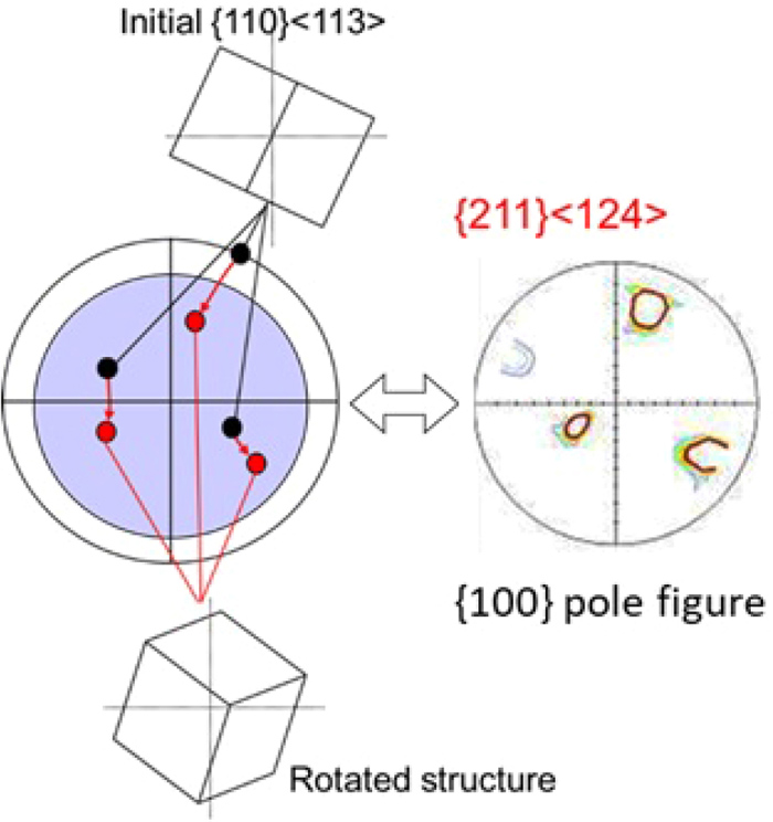
Crystal rotation behavior of specimen B-1 with an initial crystal orientation of {110}<113>, using the {110}<111> slip system. (Online version in color.)

Effect of the crystal geometric m value on the S value of the {112}<111> and {110}<111> slip systems. (Online version in color.)
The Si content may be another reason why the {110} slip system is more active. Opinsky and Smolvchowsky28) reported that the critical resolved shear stress (CRSS) for the {110} plane was smaller than that for other slip planes in an Fe–Si alloy, and Takeuchi et al.29) reported that the {110} slip system tended to take precedence over the {112} slip system in 4.4 mass% Si steel. Kamijo30) proposed an index for the relative resolved shear stress, and reported that it was in agreement with the experimental results when it was calculated assuming that the stress for the {110} slip system was increased by ca. 5%.
Therefore, it is considered that crystal rotation caused by activation of the {110} slip system occurs in the specimen with an initial orientation of {110}<113>, when the SFs for the {112} and {110} slip system are close to each other, because of a possible large value of m as well as the influence of the CRSS in Si-containing steels.
In a study by Zhang et al.,21) rolling produced a weak {113}<361> texture (which is close to {211}<124>) when the initial crystal orientation was {110}<229>. This behavior could be reproduced by simulations using a viscoplastic self-consistent model. It is supposed that the deformation behavior is similar, although the sharp texture as that in the present work has not been obtained.
The deformation behavior observed in the present experiments is peculiar and has rarely been observed in previous experiments using coarse crystals, and it may not occur in polycrystals. However, it is considered that such deformation can occur even during industrial steel rolling if constraints similar to those in the present study are imposed.
4.2. Influence of Initial Crystal Orientation on Carburized SpecimensComparing the intensities of {111}<112> in Figs. 5 and 7, which is the main rolling-induced texture component, the intensity of the main component for the carburized steel is lower than that without carburization. The EBSD image for the carburized steel in Fig. 8 indicates that the deformation is not caused by uniform slip deformation, as with the steel without carburization in Fig. 6, but various deformation substructures including deformation twins are found. These results clearly indicate that the deformation behavior during rolling is very different due to the presence of carbon in steel, even with the same initial crystal orientation.
When a specimen without carbon and with a initial crystal orientation of {110}<113> is rolled, the rolling-induced texture is expected to exhibit a strong peak near {211}<124> because the {110} slip system is activated. However, when carburized specimens with the same initial crystal orientation were rolled, the multiple structures were observed, such as deformation twins and deformation bands in one crystal grain, and each was rotated by different amounts. Similar to deformation in polycrystals, it is considered that multiple {110} and {112} slip systems are activated and are responsible for the RD elongation of the sample. As a result, a texture of {211}<113> to {111}<112> is formed.
The characteristic difference in the structure after rolling between specimen A-1 with no carbon and specimen A-2 with carbon is that deformation twins are formed in the latter case, forming a texture sub-component near {100}<011>, as indicated by the ODF. The reason why deformation twinning tends to occur in the presence of carbon is considered to be that slip deformation due to dislocations is suppressed due to the presence of carbon and fine carbide precipitates, so that twinning deformation is prioritized.17) In this case, twinning occurs in the early stage of rolling,17,18) regardless of the initial crystal orientation.
Figure 12 shows a schematic diagram of deformation twins formed for different initial crystal orientations. Unlike the case of slip deformation, the twinning plane is always {112}, and the crystal rotation that occurs is also constant. Therefore, if the initial crystal orientation is fixed, then the crystal orientation inside the twins after deformation is the same. If the initial crystal orientation is {110}<001>, then the crystal orientation inside twins is close to {100}<011>. This orientation is maintained during the rolling process and is observed as a sub-texture component in Fig. 7. On the other hand, when the initial crystal orientation is {110}<113>, the orientation inside the twins is {411}<113> (near {100}<013>). Unlike the case for {100}<011>, the {100}<013> orientation is not stable during rolling, and the crystal orientation is not maintained.

Schematic diagram of the crystal orientation in the twin structure.
As discussed in section 4.1, the SF for a slip system that was effective for twinning was determined, and the {112} slip system was identified to yield the maximum value. However, assuming that the {110} slip system is activated because of elongation in the RD, and the {110} slip system takes precedence over the {112} slip system in high Si steels, the crystal orientation in the twins rotates to approximately {111}<112> during rolling (Fig. 13). As a result, when the initial crystal orientation is {110}<113>, no clear secondary crystal orientation is observed in Fig. 7, although a band-like internal structure caused by deformation twinning (Fig. 8) is observed.

Crystal rotation behavior in the twin structure using the {110}<111> slip system. (Online version in color.)
In actual manufacturing processes, rolling-induced texture is formed in the presence of carbon in steel. In the case of an initial crystal orientation of {110}<001> or {110}<113>, the rolling-induced texture tends towards {111}<112>, regardless of the initial crystal orientation, and the peak intensity of that crystal orientation has a similar value. However, deformation within the grains showed significant differences among the individual specimens. Each specimen is expected to exhibit a different microstructure after primary recrystallization annealing due to the individual internal rolling-induced structure.
The influence of initial crystal orientation and carbon content in 3.2 mass% Si steel on cold-rolling-induced texture was investigated using quasi-single crystals. The crystal orientations of {110}<001> and {110}<113>, which are formed close to steel sheet surfaces by hot rolling and subsequent annealing, were used as the initial crystal orientations for cold rolling.
In the absence of carbon, the initial crystal orientation of {110}<001> rotated to form the stable rolling-induced crystal orientation {111}<112> by cold rolling. On the other hand, the initial orientation of {110}<113> rotated to near {211}<124>, which is not known to be a stable rolling-induced orientation. It is considered that this crystal orientation may become stable when there are constraints due to sample shape and crystal orientation, and when the {110} slip system is preferentially activated.
In the presence of carbon, when the initial crystal orientation was {110}<001>, a {100}<011> orientation formed by deformation twinning was observed together with a {111}<112> orientation after rolling. Both crystal orientations had the same deformation direction that coincided with the RD. On the other hand, when the initial crystal orientation was {110}<113>, the rolling-induced texture was {211}<113> to {111}<112>. Deformation twinning also occurred in this case, although the crystal orientation in the twins rotated to near {111}<112>. When the initial crystal orientation was {110}<113>, the {110} slip system tended to be preferred over the {112} slip system with the highest SF.