Abstract
The precipitation behavior of carbides in modified 9Cr-1Mo steel (Grade 91) subjected to low-temperature tempering and the influence of those carbides on the mechanical properties at room temperature were investigated. An as-quenched sample (AQ) contained a small amount of metal carbide (MC) in its martensite microstructure. On low-temperature tempering at 300–500°C, intended to suppress the recovery and growth of the dislocation substructure, three types of carbide were formed; these were identified as Fe4C, hP8-type Fe3C, and oP16-type Fe3C by using replica samples for transmission electron microscopy and extracted-residue analyses. Samples subjected to double low-temperature tempering at 500°C for 5 min and then at 300°C for 1 h (DLTT) contained large amounts of carbide compared with the AQ sample, but had similar a lath width. The hardness of the DLTT sample was higher than that of the AQ sample, whereas its tensile strength was slightly lower than that of the AQ sample, regardless of the strain rate. The reason that precipitation strengthening did not increase tensile strength is considered to be the early formation of microvoids due to delamination at the carbide/matrix interfaces during tensile testing.
1. Introduction
Steel is widely used as structural material over a wide temperature range because of its superior mechanical properties and this temperature range is expected to expand.1,2) Because ferrite/martensite steels containing 9–12% Cr have excellent mechanical strengths at high temperatures coupled with low coefficients of thermal expansion, they are widely used as materials for the boiler tubes of thermal power plants.3,4,5) In particular, modified 9Cr–1Mo steel (Grade 91 steel) has been used for about 40 years as a typical ferrite/martensite steel.6)
Grade 91 steel, like other ferrite/martensite steels, is treated by austenitization and tempering. The conventional heat-treatment process for Grade 91 steel involves austenitization at 1040–1060°C and tempering at 730–780°C.7) A martensite microstructure with a fine grain and a high dislocation density is formed by quenching after austenitization. Tempering is carried out at a temperature above the service temperature (~600°C) to increase the toughness of the steel and to suppress changes in its microstructure through precipitation of MX carbonitride and M23C6 phases during use.8,9)
Grade 91 steel is likely to be used in the reactors of the next generation of nuclear plants, which have much lower operating temperatures (300–500°C) than thermal power plants.5,10,11) In these cases, good mechanical properties at low and room temperatures are required. However, mechanical properties such as the yield strength and ultimate tensile strength are reduced by conventional tempering due to recovery of a dislocation substructure. For example, as-quenched Grade 91 steel has a yield strength of 1200 MPa and excellent ductility of about 15% plastic strain at room temperature, but the yield strength drops to 550–600 MPa after tempering at 760°C for one to two hours.12,13,14)
Several methods for improving the mechanical properties of Grade 91 steel at low and room temperatures have been investigated. Equal-channel angular pressing (ECAP) is a process in which a large amount of strain is introduced into the material and improves the yield strength by grain-refinement strengthening.12,13,15) However, the introduced strain markedly reduces the ductility of the steel, and heat treatment is required to remove the strain, which decreases its strength. Therefore, work hardening, like ECAP, is ineffective in producing greater strength without loss of ductility. On the other hand, it has been reported that low-temperature tempering at 300–500°C can improve both ductility (engineering strain of ~20%) and strength at room temperature (0.2% proof strength: 1370 MPa; ultimate tensile strength: 1506 MPa).16) The sharp increase in strength is thought to be due to precipitation strengthening by transition-metal carbides such as oP16-type Fe3C and hP8-type Fe3C during the low-temperature tempering.
There are four types of strengthening mechanism for Grade 91 steel at low and room temperatures: grain-refinement strengthening, dislocation strengthening, precipitation strengthening with carbides, and solid-solution strengthening.17) During low-temperature tempering, the precipitates formed should consist of Fe carbides, but recovery of the dislocation substructure, grain growth, and coarsening rarely occur. This is because the diffusion of elements other than carbon hardly occurs. Precipitation of Fe carbides reduces the carbon content of the matrix thereby weakening the solution strengthening. Therefore, to achieve an improvement in the strength of Grade 91 steel by low-temperature tempering, it is essential to understand the effects of solid-solution strengthening by carbon and of precipitation strengthening by carbides.
In this study, we prepared low-temperature tempered Grade 91 steel containing more carbides and retaining a similar dislocation density and lath width to as-quenched Grade 91 steel. By using the Grade 91 steels subjected to completely different precipitation strengthening and solid-solution strengthening processes, the effect of carbides formed by low-temperature tempering on the mechanical properties at room temperature was investigated.
2. Experimental Procedure
The steel studied was a Grade 91 steel (ASME SA335M P91). Samples subjected to heat treatment by austenitization at 1050°C for 10 min then tempering at 770°C for 30 min are referred to as conventional heat treatment (CH) samples. CH samples austenitized at 1050°C for 30 min then quenched are referred to as as-quenched (AQ) samples. The chemical composition of the AQ sample is shown in Table 1. AQ samples were subjected the low-temperature tempering at 300–600°C for up to 480 h. Some of these samples were subjected to double low-temperature tempering (DLTT) in which tempering is performed at different temperatures. All heat treatments were performed in an air atmosphere. Grade 91 steel can undergo martensitic transformation on air quenching, but water quenching was performed to suppress tempering and bainite transformation during cooling.16,18,19,20) Specimens for examination by scanning electron microscopy (SEM) were prepared by electrical-discharge machining, polishing with emery paper, and buffing with diamond slurry and colloidal silica. Samples for transmission electron microscopy (TEM) were cut into cylinders 3 mm in diameter and mechanically polished to a thickness of 50–70 μm, followed by twin-jet electropolishing using an ethanolic solution of 10% perchloric acid. Phase identification of carbides was performed by the carbon-replica technique and by extraction-residue analysis. Observations by TEM and composition analysis by energy-dispersive X-ray spectroscopy (EDX) were carried out for the carbides in the replica specimen. Specimens for extraction-residue analysis were polished with emery paper and then extracted by using a 10% acetylacetone–1% tetramethylammonium chloride solution in methanol. The extracted specimen was subjected to X-ray diffraction (XRD) analysis. The mechanical properties at room temperature were evaluated by Vickers hardness testing and tensile testing. The load for the Vickers hardness test was 4.9 N. The specimen for tensile testing was formed by electrical-discharge machining into a dog-bone shape with a gage length of 5 mm, a width of 2 mm, and a thickness of 1 mm; after removal of about 100 μm of the electrical-discharge-machined layer, the sample was polished with emery paper of #1200. The strain rates for the tensile test were 1 × 10⁻² s−1 and 1 × 10⁻⁴ s–1.
Table 1. The chemical composition (wt.%) of the as-quench (AQ) sample.
| Sample | C | Cr | Mo | V | Nb | Mn | N | S | P | Si | Ni |
|---|
| AQ | 0.09 | 8.58 | 0.94 | 0.21 | 0.07 | 0.35 | 0.04 | <0.01 | 0.01 | 0.22 | 0.04 |
3. Results and Discussion
3.1. Phase Identification of Precipitates Formed by Tempering
Figure 1 shows a back-scattered electron scanning electron microscopy (BSE-SEM) image and a bright-field transmission electron microscopy (BF-TEM) image of the AQ sample and BF-TEM images obtained from carbon-replica samples of the AQ sample and from samples tempered at 500°C for 100 h or at 300°C for 100 h. AQ sample, as previously reported,12) has a martensite microstructure with prior austenite grain, packet, block, and lath (Figs. 1(a) and 1(b)). The prior austenite grain size was 153 μm and the lath width was 307 ± 74 nm. Spherical precipitates with diameters of 30–100 nm were also observed (Fig. 1(c)). The wavy area with a dark contrast is considered to represent the unevenness of the replica formed by the grain boundaries and packet boundaries, because no diffraction pattern was obtained from this area. In samples tempered at 500°C for 100 h or at 300°C for 100 h, in addition to spherical precipitates, blocky or rod-shaped precipitates were observed (Figs. 1(d) and 1(e)).

Figure 2 shows the XRD patterns of the AQ sample and the extracted specimens of a sample tempered at 300–600°C for 100 h, together with calculated patterns of carbides.21,22,23,24) Only peaks for cF8-type transition-metal carbide phase were present in the AQ sample (Fig. 2(a)). The observed peaks were shifted toward a higher angle compared with the calculated pattern for NbC. It can be considered that elements with a smaller atomic size than Nb (0.1625 nm), such as Cr (0.1423 nm), Mo (0.1550 nm), V (0.1491 nm), Mn (0.1428 nm), or Fe (0.1411 nm) can also occupy M sites in the MC and that these elements reduce the lattice parameter compared with that of NbC.25) The peaks of the MC phase were present in all the tempered samples (Figs. 2(b)–2(e)). In addition, peaks for a cF116-type M23C6 phase were also observed in the sample tempered at 600°C for 100 h (Fig. 2(b)). On the other hand, peaks for phases other than the M23C6 phase were observed at about 40° and 45° in the sample tempered at 500°C for 100 h (Fig. 2(c)). Samples tempered at 300 and 400°C for 100 h also showed an increased intensity of the peak at about 40°, and peaks at about 44° and 46° were observed (Figs. 2(d) and 2(e)). The peaks at about 40° and 46° are on the low-angle side of the strongest and second strongest peaks of the cP5-type Fe4C phase, and their intensity ratio is similar to the calculated patterns for the cP5-type Fe4C phase. The peaks at about 44° and 45° coincide with the strongest peaks of the hP16-type Fe3C phase and the oP16-type Fe3C phase, respectively. These peaks at about 40°, 44°, and 46° are relatively broad, because they overlap with the peaks of the oP16-type Fe3C phase. Therefore, it can be concluded that the peaks at about 40° and 46° arise from an Fe4C phase, the peak at about 44° arises from an hP16-type Fe3C phase, and the peak at about 45° arises from an oP16-type Fe3C phase.

The MC phase did not dissolve in the matrix during austenitization and was present in all the tempered samples. An Fe4C phase, an hP8-type Fe3C phase, and an oP16-type Fe3C phase precipitated on tempering at 300–400°C. An Fe4C phase and an oP16-type Fe3C phase precipitated at 500°C, whereas only the M23C6 phase precipitated at 600°C.
It has been reported that the hP8-type Fe3C phase and the oP16-type Fe3C phase precipitate at below 500°C in Grade 91 steel.16,26) In addition to these phases, the formation of a Fe4C phase was also confirmed in the present study by phase identification of carbides by extraction-residue analysis.
3.2. Change in Microstructure with Tempering
Figure 3 shows BSE-SEM and BF-TEM images obtained from a carbon replica of a sample tempered at 500°C for 5 min. A large amount of carbide was present in the grain interior (Fig. 3(a)). The carbides had rod, lump, and needle shapes with a dark contrast (Figs. 3(b) and 3(c)). However, the total amount of carbides was reduced on tempering at 500°C for 100 h (Fig. 1(c)). It is reported that segregation of C occurs at the lath boundary and at dislocations in the lath of as-quenched samples.27,28) At 500°C, carbides initially formed through supersaturation of the segregated C; however, these carbides dissolve on further tempering at 500°C because they are metastable.
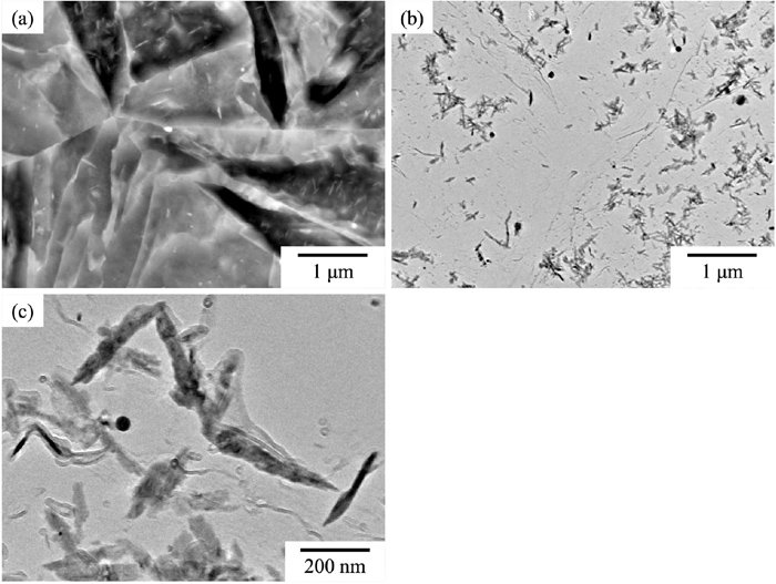
Double low-temperature tempering (DLTT) was then tested as a means of maximizing the precipitation of carbides while suppressing the recovery of the dislocation substructure and grain growth. For DLTT, an initial tempering at 500°C for 5 min was followed by a second tempering at 300°C. The aim of the first tempering was to form metastable carbides by a short treatment at 500°C, whereas the aim of the second tempering was to form more carbides through supercooling at a lower temperature. The self-diffusion coefficient of Fe in α-Fe is less than 10–22 m2/s at 500°C and less than 10–24 m2/s at 300°C.29) Based on these data, the diffusion distance at 500°C for 5 min is less than 0.17 nm and that 300°C for 1 h is less than 0.06 nm. These indicate that Fe atoms hardly diffuse during tempering at 500°C for 5 min or subsequently on tempering at 300°C. It can therefore be assumed that substitutional elements do not diffuse, and that recovery of the dislocation substructure and grain growth does not occur during DLTT. Hereafter, the samples subjected to DLTT are referred to by using the second tempering time at 300°C.
Figure 4 shows BSE-SEM, BF-TEM images, and BF-TEM images obtained from the carbon replica together with the TEM-EDX profiles of carbides in a sample subjected to DLTT for 1 h (DLTT/1 h). A large amount of carbide was observed within the grain interior (Fig. 4(a)). The lath width was almost unchanged compared with that of the AQ sample (Fig. 4(b)). Carbides with rod, lump, and needle shapes were present in the sample tempered at 500°C for 5 min. These rod-, lump-, and needle-shaped carbides contained Fe and were identified as Fe-based carbides. The only spherical carbide contained Nb, and this was identified as an Nb-rich MC carbide (Figs. 4(c)–4(e)). The Cu peaks detected in all carbides are thought to have arisen from the Cu grid of the carbon-replica sample. Figure 5 shows BF-TEM images and selected-area diffraction patterns of the rod-, lump-, and needle-shaped carbides obtained from the carbon replica of the DLTT/1 h sample, together with XRD pattern and calculated patterns of the carbides. The rod-, lump-, and needle-shaped carbides were identified as a Fe4C phase, an hP8-type Fe3C phase, and an oP16-type Fe3C phase, respectively. In addition, the XRD profile of the extracted specimen was almost the same as that of a sample tempered at 400°C and 300°C for 100 h, as shown in Figs. 2(d) and 2(e). Therefore, the carbide formed during DLTT is the same as that formed during tempering at 300–400°C. It can therefore be concluded that tempering at 500°C for 5 min followed by DLTT is effective in forming large amounts of carbide.

A sample containing saturated carbon in the matrix (AQ sample) and a sample in which a large amount of carbide was produced by DLTT for 1 h were prepared. These samples were subjected to hardness and tensile testing at room temperature to investigate the effects of solid-solution strengthening by carbon and precipitation strengthening by carbides on the mechanical properties of Grade 91 steel.
Figure 6 shows the change in the hardness of the samples with the tempering time. The hardness of the AQ sample was 400 ± 8 HV. At 500°C, the hardness reached a maximum value of 431 ± 3 HV and then decreased. The increase of hardness by tempering for a short time might be caused by the precipitation of fine Fe3C and Fe4C phases. However, they were re-solved by a long time tempering, resulting in a reduction of the pinning effect and the recovery of the dislocation substructure. On the other hand, at 300°C, the hardness decreased at the beginning of tempering, but then began to increase, reaching 386 ± 3 HV before decreasing again. The decrease of hardness by tempering for a short time might be caused by a decrease in solid-solution strengthening within the grain interior due to diffusion of saturated carbon toward the boundaries. Subsequently, the hardness begins to increase with precipitation of carbides. DLTT for 0.5–1 h increased the hardness compared with that of the sample tempered at 500°C for 5 min, and further tempering monotonically decreased the hardness. It is considered that both the first tempering (at 500°C for 5 min) and the second tempering result in the formation of fine carbides. The decrease of hardness after 1 h of DLTT is considered to be due to coarsening of the carbides.

Figure 7 shows the tensile engineering stress–plastic strain curves at strain rates of 1 × 10⁻² s–1 and 1 × 10⁻⁴ s–1 at room temperature of the AQ sample and the DLTT/1 h sample. These curves were similar and showed work hardening of up to 2% of the plastic strain after yielding, but the stress saturated and then decreased until fracture. The fracture strain of all samples was about 20%. None of the samples showed a strain rate dependence. The plastic deformation of ferritic steels might be controlled by a thermally activated process of dislocation.30) However, since little strain rate dependence was observed for this steel, room temperature is considered to be a temperature range where the temperature dependence is relatively small. On the other hand, the strength of the AQ sample was slightly higher than that of the DLTT/1 h sample.

Table 2 summarizes the results of the analyses of the microstructure and mechanical properties of AQ sample and DLTT/1 h sample. The DLTT/1 h sample contained more carbides and had a greater hardness but a lower yield strength and a lower ultimate tensile strength than the AQ sample. Therefore, the carbides formed during the low-temperature tempering contribute to an increase in hardness but do not affect the tensile strength. The cause of this is discussed below.
Table 2. Microstructure and mechanical properties of the AQ and DLTT/1 h samples.
| Samples | Microstructures | Mechanical properties |
|---|
| Lath width (nm) | Types of precipitates | Hardness (HV) | σ0.2 (MPa) | σUTS (MPa) |
|---|
|
ε
˙
= 1×10⁻² s−1 |
ε
˙
= 1×10⁻⁴ s−1 |
ε
˙
= 1×10⁻² s−1 |
ε
˙
= 1×10⁻⁴ s−1 |
|---|
| AQ | 307 ± 74 | MC (cF8) | 400 ± 8 | 1110 ± 45 | 1140 ± 49 | 1410 ± 4 | 1430 ± 3 |
| DLTT/1 h | 318 ± 170 | MC (cF8) + M4C (cP5) + M3C (oP16) + M3C (hP8) | 440 ± 3 | 1070 ± 18 | 1110 ± 2 | 1320 ± 4 | 1320 ± 10 |
Figure 8 shows fractographs of the AQ sample and the DLTT/1 h sample after tensile testing at a strain rate of 1 × 10⁻² s–1. Both samples showed dimples and typical ductile-fracture surfaces. However, the dimples on the DLTT/1 h sample were finer and denser than those on the AQ sample. When a metal has inclusions such as carbides, the dimple size decreases and the density of dimples increases with increasing density of the inclusions.31) Dimple formation is caused by microvoids due to stress concentration around inclusions during plastic deformation.32) In the tensile engineering stress–plastic strain curves at room temperature of the AQ sample and the DLTT/1 h sample (Fig. 7), both samples show a peak stress immediately after yielding, followed by a gradual decrease in stress accompanied by a higher fracture strain. This could be the specific behavior of ductile metals with large amounts of fine hard inclusions. In addition, peak stress is associated with the generation of microvoids, and the decrease in the deformation stress is caused by the formation of microvoids of carbide origin. Therefore, it is considered that microvoids are initially generated at a strain smaller than the strain at the peak stress. Because the density of microvoids in the DLTT/1 h sample is higher than that in the AQ sample, the effective deformation area of the DLTT sample is smaller than that of the AQ sample. These effects might decrease the deformation stress of the DLTT/1 h sample compared with the AQ sample from the early stages of plastic deformation. On the other hand, because the generation of microvoids is relatively suppressed in the hardness test, the hardness is clearly increased by precipitation strengthening by carbides.

4. Conclusions
In this study, by using a sample containing saturated carbon in the matrix (AQ sample) and a sample in which large amounts of carbide were formed by low-temperature tempering (DLTT for 1 h), the precipitation behavior of carbides in modified 9Cr-1Mo steel (Grade 91) subjected to low-temperature tempering and the influence of those carbides on the mechanical properties of the steel at room temperature were investigated. The conclusions are summarized as follows:
(1) The carbides precipitated by low-temperature tempering at 300–400°C or 500°C for a short time consist of an Fe4C phase, an hP8-type Fe3C phase, and an oP16-type Fe3C phase.
(2) Only an undissolved MC carbide phase was observed in the AQ sample. The sample subjected to DLTT for 1 h contained large amounts of a rod-shaped Fe4C phase, a lump-shaped hP8-type Fe3C phase, and a needle-shaped oP16 type Fe3C phase, whereas the lath width and dislocation density were maintained.
(3) The carbides formed during low-temperature tempering contribute to an increase in hardness but do not affect the tensile strength. It can be concluded that microvoids formed at the interface between the carbides and the matrix reduce the effective deformation area.
Acknowledgement
This research was financially supported by the Advanced Research and Education Center for Steel of the Department of Metallurgy, Materials Science and Materials Processing, Graduate School of Engineering, Tohoku University.
References
- 1) S. Jiang, H. Wang, Y. Wu, X. Liu, H. Chen, M. Yao, B. Gault, D. Ponge, D. Raabe, A. Hirata, M. Chen, Y. Wang and Z. Lu: Nature, 544 (2017), 460. https://doi.org/10.1038/nature22032
- 2) Y. H. Gao, S. Z. Liu, X. B. Hu, Q. Q. Ren, Y. Li, V. P. Dravid and C. X. Wang: Mater. Sci. Eng. A, 759 (2019), 298. https://doi.org/10.1016/j.msea.2019.05.039
- 3) R. L. Klueh: Int. Mater. Rev., 50 (2005), 287. https://doi.org/10.1179/174328005X41140
- 4) F. Abe: Engineering, 1 (2015), 211. https://doi.org/10.15302/J-ENG-2015031
- 5) R. L. Klueh and A. T. Nelson: J. Nucl. Mater., 371 (2007), 37. https://doi.org/10.1016/j.jnucmat.2007.05.005
- 6) R. L. Klueh: Elevated-Temperature Ferritic and Martensitic Steels and Their Application to Future Nuclear Reactors, Oak Ridge National Laboratory, Oak Ridge, TN, (2005), ORNL/TM-2004/176. https://doi.org/10.2172/885938, (accessed 2022-03-28).
- 7) C. Pandey, M. M. Mahapatra, P. Kumar and N. Saini: J. Alloy. Compd., 743 (2018), 332. https://doi.org/10.1016/j.jallcom.2018.01.120
- 8) M. Taneike, F. Abe and K. Sawada: Nature, 424 (2003), 294. https://doi.org/10.1038/nature01740
- 9) F. Abe: Sci. Technol. Adv. Mater., 9 (2008), 013002. https://doi.org/10.1088/1468-6996/9/1/013002
- 10) C. Fazio, A. Alamo, A. Almazouzi, S. De Grandis, D. Gomez-Briceno, J. Henry, L. Malerba and M. Rieth: J. Nucl. Mater., 392 (2009), 316. https://doi.org/10.1016/j.jnucmat.2009.03.020
- 11) S. Konishi and M. Enoeda: J. At. Energy Soc. Jpn., 47 (2005), 488 (in Japanese). https://doi.org/10.3327/jaesj.47.488
- 12) M. Song, C. Sun, Z. Fan, Y. Chen, R. Zhu, K. Y. Yu, K. T. Hartwig, H. Wang and X. Zhang: Acta Mater., 112 (2016), 361. https://doi.org/10.1016/j.actamat.2016.04.031
- 13) Z. Q. Fan, T. Hao, S. X. Zhao, G. N. Luo, C. S. Liu and Q. F. Fang: J. Nucl. Mater., 434 (2013), 417. https://doi.org/10.1016/j.jnucmat.2012.12.009
- 14) C. Pandey, A. Giri and M. M. Mahapatra: Mater. Sci. Eng. A, 657 (2016), 173. https://doi.org/10.1016/j.msea.2016.01.066
- 15) M. Song, R. Zhu, D. C. Foley, C. Sun, Y. Chen, K. T. Hartwig and X. Zhang: J. Mater. Sci., 48 (2013), 7360. https://doi.org/10.1007/s10853-013-7522-3
- 16) Z. Shang, J. Ding, C. Fan, M. Song, J. Li, Q. Li, S. Xue, K. T. Hartwig and X. Zhang: Acta Mater., 169 (2019), 209. https://doi.org/10.1016/j.actamat.2019.02.043
- 17) K. Marukawa: Tetsu-to-Hagané, 91 (2005), 445 (in Japanese). https://doi.org/10.2355/tetsutohagane1955.91.5_445
- 18) T. Sasaki, K. Kobayashi, T. Yamaura, T. Kasuya and T. Masuda: Kawasaki Steel Giho, 22 (1990), 257 (in Japanese). https://www.jfe-steel.co.jp/archives/ksc_giho/22-4/j22-257-265.pdf, (accessed 2022-03-28).
- 19) D. A. Carrizo, J. I. Besoky, M. Luppo, C. Danon and C. P. Ramos: J. Mater. Res. Technol., 8 (2019), 923. https://doi.org/10.1016/j.jmrt.2018.07.004
- 20) R. W. Swindeman, M. L. Santella, P. J. Maziasz, B. W. Roberts and K. Coleman: Int. J. Press. Vessel. Pip., 81 (2004), 507. https://doi.org/10.1016/j.ijpvp.2003.12.009
- 21) T. G. Utkina: Inorg. Mater., 31 (1995), 854.
- 22) R. Berkane, J. C. Gachon, J. Charles and J. Hertz: Calphad, 11 (1987), 375. https://doi.org/10.1016/0364-5916(87)90035-6
- 23) Z. G. Pinsker and S. V. Kaverin: Sov. Phys. Crystallogr., 1 (1956), 48.
- 24) K. H. Jack: Acta Crystallogr., 3 (1950), 392. https://doi.org/10.1107/S0365110X50001075
- 25) H. W. King: J. Mater. Sci., 1 (1966), 79. https://doi.org/10.1007/BF00549722
- 26) C. Hurtado-Noreña, C. A. Danón, M. I. Luppo and P. Bruzzoni: Procedia Mater. Sci., 8 (2015), 1089. https://doi.org/10.1016/j.mspro.2015.04.172
- 27) T. Masumura, T. Taniguchi, S. Uranaka, I. Hirashima, T. Tsuchiyama, N. Maruyama, H. Shirahata and R. Uemori: Tetsu-to-Hagané, 106 (2020), 835 (in Japanese).
- 28) B. Hutchinson, J. Hagström, O. Karlsson, D. Lindell, M. Tornberg, F. Lindberg and M. Thuvander: Acta Mater., 59 (2011), 5845. https://doi.org/10.1016/j.actamat.2011.05.061
- 29) B. Zhang: AIP Adv., 4 (2014), 017128. https://doi.org/10.1063/1.4863462
- 30) H. Conrad: J. Met., 16 (1964), 582. https://doi.org/10.1007/bf03378292
- 31) M. Mori: J. High Press. Inst. Jpn., 12 (1974), 232 (in Japanese). https://doi.org/10.11181/hpi1972.12.232
- 32) G. Y. Chin, W. F. Hosford and W. A. Backofen: Trans. Metall. Soc. AIME, 230 (1964), 437.
