Abstract
To establish a low-carbon society, it is necessary to break away from dependence on fossil fuels, and the utilization of geothermal energy/waste heat is one of the key methods. When using geothermal energy, the rate of heat transfer decreases with time due to the precipitation of scale on the heat transfer surface, and periodic maintenance is required. Therefore, the running cost of utilizing geothermal energy is high. We focused on a rotary heat exchanger consisting of a rotating cylinder as the heat transfer wall and a fixed blade attached to the rotating cylinder for scraping the heat transfer surface. In this study, the heat recovery characteristic from chloride hot spring was experimentally evaluated. The results showed that scale formation on the heat transfer surface could be suppressed and the heat transfer characteristics could be maintained for one month.
1. Introduction
To establish a low-carbon society, dependence on fossil fuel should be avoided. To reduce the use of fossil fuel, the new processes such as unused heat recovery,1,2) promotion of renewable energy utilization,3,4,5,6,7) and improvement in various process efficiencies have been required. In these processes, the key technology is heat exchanger. Although the heat exchangers have been developed and used so far, they were developed for the clean environment. On the other hand, heat exchangers that can be used in non-clean environments are critical in recent applications. For example, the scale of geothermal utilization8,9,10) and the solidified layer in latent heat storage (LHS)5,6,11,12,13,14) cover the heat exchange wall heat exchange wall and impede efficient heat transfer. The heat transfer rate decreases significantly due to the thermal resistance in the covered layer, as shown in Fig. 1. Therefore, in conventional heat exchangers, the disassembly of the heat exchanger and cleaning of heat transfer surfaces are performed frequently. In this context, plate-or shell-and-tube-type heat exchangers are rarely used under impure conditions, whereas tube-type heat exchangers are generally used, although the heat transfer characteristics of tube-type heat exchangers are unsatisfactory for efficient heat exchange. Therefore, a less-maintenance heat transfer system that can be used under non-clean conditions is highly required to promote the abovementioned energy utilizations.

The authors developed a rotating heat exchanger to solve the aforementioned problem. Figure 2 shows a schematic representation of the rotating heat exchanger consisting of a tube-type heat exchanger comprising a rotating cylinder as the heat exchange wall and a fixed blade attached to the rotating cylinder.11) Figure 3 shows a cross-sectional image of the heat exchanger.11) When the solid phase precipitated on the outer surface of the rotating cylinder, the precipitates were scraped immediately by the fixed blade in contact with the rotating cylinder, and the heat transfer surface was refreshed continuously.11)


This heat exchanger was originally proposed by Chiba et al., and high heat transfer characteristics achieved by removing the thermal boundary layer on the both heat exchange wall surfaces have been reported.15) We extended the heat exchanger for the application of LHS system by combining a rotating cylinder and a fixed blade.11) Generally, the heat release rate of an LHS does not facilitate heat release because the heat exchange wall is shielded by the solid phase. In previous study, the heat release rate in LHS was experimentally investigated by applying the system proposed above, in which sodium acetate trihydrate was used as the phase change material (PCM), and the results showed that the heat transfer rate in LHS is enhanced by more than 100 times when using the mechanism proposed above as compared with the result of a non-rotation experiment.11) Hence, it was indicated that the control of solid adhesion on the heat transfer surface is critical for ensuring heat transfer. Although various environments exist where a solid material precipitates on the heat transfer surface, relevant experimental studies in actual environments have not been conducted.
In this study, the authors focused on a heat exchange experiment in a hot spring.16) It is well known that inorganic materials (scale) precipitate in hot springs and they inhibits heat transfer, thereby decreasing the efficiency of heat recovery.9) The authors conducted experimental studies of heat recovery in the Obama hot spring, Unzen City, Nagasaki Prefecture, Japan. This hot spring is a good heat source owing to its high temperature (exceeding 100°C) and high flow rate.17) Additionally, it is well known as a large amount of scale precipitation from hot spring in Japan.9,10) For this reason, hot water for showers is prepared using excessive heat from the hot spring in a local hot spring inn; however, maintenance to remove scale from the heat exchanger is performed frequently (every two weeks to two months). This is an important issue that must be solved to reduce the burden of management in terms of time and cost such that the use of hot spring heat can be expanded. A rotating heat exchanger might recover heat for a long time because the precipitates can be removed mechanically. However, relevant experimental studies have yet to be conducted. Therefore, the authors developed a heat exchanger for hot springs, conducted a heat recovery experiment in an Obama hot spring for approximately one month, and evaluated the change in heat transfer characteristics.
2. Experiments
2.1. Effect of Rotation Rate on Heat Transfer Rate in Hot Spring
Prior to the long-term experiment, the characteristics of the developed rotary heat exchanger16) were evaluated under hot spring conditions. Figures 4 and 5 show photographs of the rotary heat exchanger and the experimental setup used in this study. The motor rotated the heat-transfer tube via a timing belt and a part of the tube was immersed in a bath filled with hot spring water. Figure 6 shows a schematic illustration of the experimental setup. Hot spring water was supplied from the top of the bath and flowed out from the bottom of the bath. The heat exchanger has a double-tube structure, and tap water was supplied to the bottom of the heat transfer tube via the water pipe; the tap water flowed out from the top of the heat transfer tube, i.e., counterflow heat exchange occurred. The specifications of the heat exchanger and experimental conditions are summarized in Tables 1 and 2. The outer fixed blades were set to continuously peel off the precipitated scale from the hot spring,16) and the inner fixed blades were set to remove the boundary layer.15) Both blades were fixed in contact with the surface of heat transfer tube, i.e., the gap between the blade and the heat transfer tube is zero.

Table 1. Specifications of heat exchanger.
| Heat transfer tube | SUS304 |
| Diameter (O.D.) | 89.1 mmΦ |
| Thickness | 1.5 mm |
| Effective length | 483 mm |
| Rotation rate | 0–400 rpm |
| Fixed blade | |
| Outer | Polycarbonate, 4 plates |
| Inner | Polycarbonate, 4 plates |
Table 2. Experimental conditions.
| Outer medium | Chloride hot spring |
| Temperature | 100°C approximately |
| Flowrate | 5 L/min (Initial) |
| Bath volume | 90 L |
| Inner medium | Tap water |
| Temperature | 20°C approximately |
| Flowrate | 5 L/min (short term exp.) |
| 3 L/min (long term exp.) |
The experiments were conducted as follows: The rotating heat exchanger was set to a bath, whereas hot spring water and tap water were supplied to the bath and heat exchanger, respectively. The temperatures of the inlet and outlet hot spring water and tap water shown in Fig. 6 were measured using a thermocouple. The rotation rate of the heat transfer tube was changed from 0 to 400 rpm to investigate the heat transfer characteristics of the heat exchanger.
The heat transfer rate, Q, was calculated based on the temperature difference between the inflow and outflow temperatures of tap water (TW,out and TW,in), flow rate FW, and specific heat capacity of the inner fluid CP, as follows:
|
Q=
F
W
C
P
(
T
W,out
-
T
W,in
)
[ W ]
| (1) |
The heat transfer rate Q was affected by the temperature difference and heat transfer area. Therefore, the overall heat transfer coefficient, U, is often used to evaluate the heat transfer characteristics and can be calculated by Q, the heat transfer area A multiplied, and the logarithmic mean temperature difference, ΔT. For the countercurrent heat exchanger, U is defined as follows:
|
U=
Q
A×
Δ
T
A
-Δ
T
B
ln(Δ
T
A
/Δ
T
B
)
[
Wm
-2
K
-1
]
| (2) |
In this study, ΔTA and ΔTB are defined as follows:
|
Δ
T
A
=
T
S,IN
-
T
W, OUT
[K]
| (3) |
|
Δ
T
B
=
T
S, OUT
-
T
W,IN
[K]
| (4) |
where the subscript S denotes “hot spring.”
2.2. Long-term Experiment
A long-term experiment was conducted to evaluate the time variation of heat transfer characteristics under scale precipitation conditions. The experimental setup is the same as that described in the previous section, and the experimental conditions are listed in Table 2. The long-term heat exchange experiment was conducted for one month at 100 rpm. The temperature and flowrate, similar to those in the previous section, were recorded, and the heat transfer rate and overall heat transfer coefficient were analyzed. One month later, the heat exchanger was lifted up, and scale adhesion was observed. The scale was sampled and analyzed via wavelength dispersive X-ray fluorescence (XRF) after drying at 105°C for 8 h.
3. Results and Discussions
3.1. Effect of Rotation Rate on Heat Transfer Rate in Hot Spring
Figure 7 shows the effect of the rotation rate of the heat transfer tube on the outlet temperature of the hot spring water and tap water, as well as the heat transfer rate. The inlet temperatures of the hot spring water and tap water remained at approximately 100°C and 20°C, respectively, regardless of the rotation rate. The outlet temperatures of the hot spring water and tap water decreased and increased, respectively, as the rotation rate increased. These results indicate that the heat transfer from the hot spring water to the tap water was enhanced by tube rotation. The heat transfer rate calculated using Eq. (1) is also shown in Fig. 7. The heat transfer rate increased with rotation and exceeded 10 kW at larger than 300 rpm. The gradient of heat transfer rate decreased with increasing rotation because the temperature difference between the hot spring water and tap water decreased.

Figure 8 shows the relationship between the rotation rate of the heat transfer tube and the overall heat transfer coefficient calculated using Eq. (2). The overall heat transfer coefficient increased with the rotation rate and was approximately two times higher at 400 rpm compared with at 0 rpm. This trend is consistent with that observed in a previous study;15) however, the value was smaller (approximately 3000 W/m2K at 400 rpm15)). This is because SUS304 was employed for the heat transfer tube to provide corrosion resistance to the hot springs, whereas Cu was used in the previous study.
3.2. Long-term Experiment
Figures 9 and 10 show the variations in the heat transfer rate and overall heat transfer coefficient with and without rotation, respectively, for the one-month experiment. From the start of the experiment to 3 d later, the tap water supply had problems. The flow rate of the hot spring was adjusted at intervals of approximately 3 d because the clogging of scale from the hot spring was occurred in the feed line. The feed line of hot spring water was washed out approximately 17, 24, and 28 d later. The data for these periods are scattered and shown in light colors in Figs. 9 and 10.

Without rotation, i.e., analogous to a conventional heat exchanger, the heat transfer rate and overall heat transfer coefficient decreased gradually. The initial heat transfer rate and overall heat transfer coefficient were approximately 5000 W and 600 W/m2K, respectively, and approximately 4000 W and 400 W/m2K, respectively, 20 d later; they decreased by 20% and 34%, respectively, after 20 d. Thereafter, this decreasing trend continued.
By contrast, the heat transfer rate and overall heat transfer coefficient first decreased (approximately 10 d) and then remained almost constant with rotation. The initial heat transfer rate and overall heat transfer coefficient were approximately 7000 W and 1200 W/m2K, respectively, and approximately 5500 W and 850 W/m2K 10 d later, i.e., these values decreased by 21% and 29%, respectively, after 10 d. Subsequently, they remained constant. The improvement ratio, which is defined as the value with rotation divided by the value without rotation, increased with time from 1.3 to 2.3 for the heat transfer rate and from 1.8 to 3.1 for the overall heat transfer coefficient. The initial overall heat transfer coefficient with rotation was 1.8 times higher than that without rotation in the experimental condition involving a rotation rate of 100 rpm. As shown in Fig. 7, the overall heat transfer coefficient increased with the rotation rate; therefore, by increasing the rotation rate, the improvement value and heat transfer rate are expected to increase.
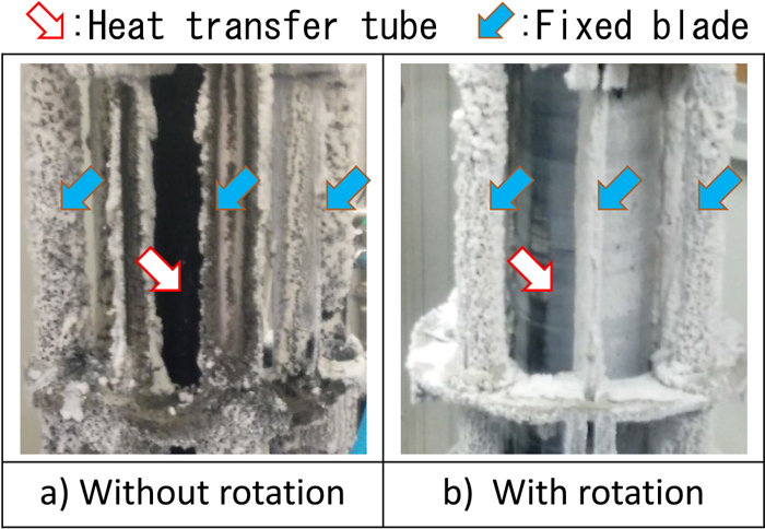
Figure 11 shows photographs of the heat exchanger after a one-month heat-exchange experiment. The scale was adhered onto the heat exchanger surface. The outer fixed blades, including the support parts, were covered by a white scale, regardless of the rotation. XRF analysis showed that the main components of the white scale were Si and Mg. According to Morita et al., this phase indicates amorphous magnesium silicate.10) Black scale appeared under the white scale, and it was a Si–Mg-based scale with 5–10 mass% Fe and S according to XRF analysis. The heat-transfer tube without rotation was fully covered with black scale. Meanwhile, the heat transfer tube with rotation was covered with gray scale, which may be a mixture of white and black scales. The thickness of the scale on the heat exchange wall with rotation was substantially thinner than that on the non-rotation wall, and the heat exchange wall was partially exposed to the hot spring in the case with rotation. The scale adhesion could be suppressed by the mechanism proposed above.
3.3. Estimation of Scale Thickness
The resistance of heat transfer is defined as follows:
|
1
U
=
1
h
h
+
x
scale
λ
scale
+
x
w
λ
w
+
1
h
c
,
| (5) |
where
h is the heat-transfer coefficient of the thermal boundary layer;
λ and
x are the thermal conductivity and thickness of each phase, respectively. The subscripts h, c, w, and “scale” represent the higher temperature fluid (hot spring water in this study), lower temperature fluid (tap water in this study), heat exchange wall, and adhered scale, respectively. Left term represents the thermal resistance of overall heat transfer, and right terms represents the thermal resistances of boundary layer in high temperature side, scale, heat exchange wall, boundary layer in low temperature side, respectively. If the thermal resistance of both the boundary layer and the heat exchange wall does not change when the scale is attached to the heat exchange wall, then
Eq. (5) can be simplified as follows:
|
1
U
=
1
U
0
+
x
scale
λ
scale
,
| (6) |
where
U0 is the overall heat transfer coefficient before scale adhesion, as shown in
Fig. 8.
Figure 12 shows the comparison of thermal resistance in the scale layer and the other part with/without rotation for one-month experiment. In this figure, the thermal resistances of scale (=
xscale/
λscale) and other parts (=1/
U0) except for the scale layer were compared. The thermal resistances in the other part were assumed to be the initial whole thermal resistance because the scale layer did not exist in the initial condition. We also assumed that the thermal resistance of other part is unchanged regardless of scale layer condition. In this experimental condition (100 rpm), the thermal resistance of the other part decreased to half by rotation. The thermal resistances of scale with/without rotation showed similar value at earlier period. After 10 days lapsed, the difference of thermal resistance in the scale layer with/without rotation increased. After 30 days lapsed, the thermal resistance with rotation showed almost same value as that in the initial condition, though the thermal resistance of scale exceeded to the resistance of initial heat exchanger. As mentioned in
Fig. 8, overall heat transfer coefficient increased with rotation rate,
i.e. the thermal resistance of heat exchanger decreased with rotation rate. Thus, the negative impact of scale for heat transfer becomes relatively large by increasing rotation rate.

The scale used in this study was a Si–Mg-based wet material. The thermal conductivity of the scale was assumed to be 1.0 W/m K because the thermal conductivity of amorphous silica and sea water are 1.418) and 0.6719) W/m K, respectively. Figure 13 shows the time variation in the estimated scale thickness with and without rotation for the one-month experiment. The thickness of the scale without rotation increased linearly with time, and approximately 2.0 mm of the scale adhered to the heat transfer tube one month later. Although quantitative measurements of scale thickness could not be performed owing to technical difficulties, this value was consistent with the visual observation results. Meanwhile, the scale thickness with rotation increased with time, and the rate of increase was similar to that without rotation until day 10. However, after day 10, the increase in thickness stagnated at approximately 0.3 mm. This indicates that the proposed heat exchanger can reduce solid precipitation on the heat exchange wall and maintain a stable performance for an extended period. This mechanical system may be applied to hot springs (scale), waste heat from iron-steelmaking industry and the others (dust, sludge), river and seawater (biofilms), latent heat storage (solidified phase), etc., which may potentially facilitate the development of a sustainable society.20)

4. Conclusion
A new heat exchanger with a rotating cylindrical tube and a fixed blade was developed to remove the solid layer on a heat transfer tube. To perform a long-term evaluation of the heat release characteristics of the rotating heat exchanger in a hot spring, a heat exchange experiment was conducted in the Obama hot spring in Nagasaki, Japan. The findings obtained were as follows:
(1) The heat transfer rate and overall heat transfer coefficient of the developed heat exchanger increased with the rotation rate of the heat transfer tube.
(2) The heat transfer rate and overall heat transfer coefficient decreased with time in the case without rotation, which corresponded to the conventional heat exchanger. The heat transfer tube was fully covered by scale after 30 d of the experiment.
(3) The heat transfer rate and overall heat transfer coefficient first decreased (for approximately 10 d) and remained almost constant when the developed rotating heat exchanger was used. The scale thickness of the heat transfer tube was smaller than that without rotation.
(4) The proposed mechanism may be applied not only to hot springs (scale), but also to waste heat from iron-steelmaking industry and the others (dust, sludge), river and seawater (biofilms), latent heat storage (solidified phase), etc., which may facilitate the development of a sustainable society.
Acknowledgments
The results reported herein are based on results obtained from a project commissioned by the New Energy and Industrial Technology Development Organization (NEDO).
We would like to thank the following members of the NEDO project committee: Tadashi Takashima at Tokyo Technology University, Keiichiro Maeda of the Japan Sustainable Free Powered Energy System Exploit & Promotion Association (JASFA), Takashi Sekiba of the Miyagi Prefectural Government, Masanori Konno, Keisuke Ura and Nobuhiro Ito of the Industrial Technology Institute Miyagi Prefectural Government, Hiroshi Asanuma of the National Institute of Advanced Industrial Science and Technology (AIST), Koushi Numazawa of Tohoku TECHNO ARCH, Naofumi Nishimura and Yurie Iino, and Hiroshi Nogami at Tohoku University.
The authors would like to thank the “Dynamic Alliance for Open Innovation Bridging Human, Environment and Materials” from the Ministry of Education, Culture, Sports, Science and Technology of Japan (MEXT).
References
- 1) N. Maruoka and T. Akiyama: ISIJ Int., 42 (2002), 1189. https://doi.org/10.2355/isijinternational.42.1189
- 2) N. Maruoka, T. Mizuochi, H. Purwanto and T. Akiyama: ISIJ Int., 44 (2004), 257. https://doi.org/10.2355/isijinternational.44.257
- 3) B. Eppinger, D. Steger, C. Regensburger, J. Karl, E. Schlucker and S. Will: Appl. Energy, 288 (2021), 116650. https://doi.org/10.1016/j.apenergy.2021.116650
- 4) T. Okazaki: Renew. Energy, 151 (2020), 563. https://doi.org/10.1016/j.renene.2019.11.051
- 5) M. Wang, Y. Wang, C. Zhang and F. Yu: J. Energy Storage, 45 (2022), 103771. https://doi.org/10.1016/j.est.2021.103771
- 6) W. Liu, Y. Bie, T. Xu, A. Cichon, G. Królczyk and Z. Li: J. Energy Storage, 46 (2022), 103727. https://doi.org/10.1016/j.est.2021.103727
- 7) N. Maruoka, H. Purwanto and T. Akiyama: ISIJ Int., 50 (2010), 1311. https://doi.org/10.2355/isijinternational.50.1311
- 8) R. Hashimoto, M. Morita, O. Umezawa and S. Motoda: J. Jpn. Inst. Met., 81 (2017), 89. https://doi.org/10.2320/jinstmet.J2016045
- 9) N. Honma, H. Hayashi, T. Takase, M. Morita and T. Fuzino: Proc. Mechanical Engineering Cong., Japan, Vol. 2015, The Japan Society of Mechanical Engineers, Tokyo, (2015), J0530201. https://doi.org/10.1299/jsmemecj.2015._J0530201-
- 10) M. Morita, Y. Goto, S. Motoda and T. Fujino: J. Geotherm. Res. Soc. Jpn., 39 (2017), 191. https://doi.org/10.11367/grsj.39.191
- 11) N. Maruoka, T. Tsutsumi, A. Ito, M. Hayasaka and H. Nogami: Energy, 205 (2020), 118055. https://doi.org/10.1016/j.energy.2020.118055
- 12) L. Liu, X. Zhang, X. Xu, X. Lin, Y. Zhao, L. Zou, Y. Wu and H. Zheng: Renew. Energy, 179 (2021), 2348. https://doi.org/10.1016/j.renene.2021.07.096
- 13) S. Jegadheeswaran, A. Sundaramahalingam and S. D. Pohekar: Int. J. Thermophys., 42 (2021), 171. https://doi.org/10.1007/s10765-021-02921-x
- 14) A. Egea, A. García, R. Herrero-Martín and J. Pérez-García.
- 15) H. Nogami, K. Aonuma and Y. Chiba: ISIJ Int., 50 (2010), 1276. https://doi.org/10.2355/isijinternational.50.1276
- 16) N. Maruoka, T. Yamamoto, S. Endo, T. Aizawa, T. Ono, H. Sasaki, K. Ura, N. Ito, K. Oyama and K. Maeda: The Iron and Steel Institute of Japan, Tokyo, 140.
- 17) H. Hayashi, T. Takase, K. Umakoshi, T. Fujino, S. Kaji and H. Sasaki: Rep. Grad. Sch. Eng., Nagasaki Univ., 44 (2014), 7.
- 18) J. M. Larkin and A. J. H. McGaughey: Phys. Rev. B, 89 (2014), 144303. https://doi.org/10.1103/PhysRevB.89.144303
- 19) D. T. Jamieson and J. S. Tudhope: Desalination, 8 (1970), 393. https://doi.org/10.1016/S0011-9164(00)80240-4
- 20) N. Maruoka, T. Tsutsumi, T. Kanai and H. Nogami: 3rd Japanese-German Workshop on Renewable Energies (JGW 2018), (Tokyo), (2018), 2.


