Fundamentals of High Temperature Processes
Simulation of Thermal Decomposition of Partially Calcined Spherical Limestone Injected into a Molten Iron Bath
2022 Volume 62 Issue 3 Pages 602-605

Details
2022 Volume 62 Issue 3 Pages 602-605
To reduce the consumption of energy and materials, it is necessary to develop a more efficient method for refining iron. The use of partially calcined limestone as a refining flux is expected to increase the mass transfer and reaction area via thermal decomposition of CaCO3 and violent CO2 generation. A model was developed to simulate the decomposition of the limestone particles in molten iron using multi-physics analysis, in which the equations for multiphase flow, heat transfer, and chemical reactions were solved simultaneously. The particle penetration behavior and the temperature and mass distributions of CaCO3 were calculated as a function of time. A large amount of CO2 is generated in a short period, which is expected to generate a strong stirring effect and destroy the flux particles.
In the process of steelmaking, it is important to increase the reaction area between the flux particles and molten iron to remove impurities efficiently. To increase the rate and efficiency of the refining process, techniques that provide a larger reaction interface for the flux particles are required.
Maruoka et al.1) utilized the presence of residual CaCO3 in calcined limestone, which is used as a flux, to show that the generation of CO2 from the thermal decomposition of CaCO3 accelerates the slagging of the flux. Hara et al.2) also investigated the effect of gas generation from the limestone (CaCO3) on the process efficiency. Based on these reports, it was postulated that the use of partially calcined calcium carbonate could increase the reaction area and rate of mass transfer through the breakdown and dispersion of the flux particles, driven by CO2 generation.
In this study, a model was developed to analyze the decomposition of the limestone particles in a molten iron bath using multi-physics analysis, in which the equations for multiphase flow, heat transfer, and chemical reaction were simultaneously solved. Calculations were performed for limestone spheres and partially calcined spheres.
In this study, the particle injection model developed by Nakano et al.3,4) was used. The governing equation (Navier-Stokes) is given by Eq. (1):
| (1) |
Equation (2) defines the potential function φ, which provides the interfacial tension:
where d is the initial distance between the particles, and C is the potential coefficient. The dimensionless distance q is equal to r/h, where r is the position vector, r is its norm, and h is the effective radius. Differentiating the potential yields the force acting on each particle. Therefore, the interfacial tension force Finter is given by Eq. (3), where θ is the equilibrium contact angle. 2.2. Heat Transfer ModelIn this study, we modeled a single sphere of flux injected into a molten iron bath from above. The radiative heat transfer from the bath surface was assumed to remain dominant until the particle entered the bath. After entering the bath, heat conduction between the particle and molten iron was assumed to be the dominant mode of energy transfer.
2.2.1. Radiation ModelThe radiation heat transfer Q12 from surface 1 (temperature T1 and surface area A1) to 2 (temperature T2) can be described by the Stefan-Boltzmann law:
| (4) |
Only the iron bath and flux particle were modeled because the distance between the particle and furnace wall, along with other factors, was not clear. Therefore, the inner wall of the furnace was assumed to behave as a black body, and the radiation from the surface was calculated by replacing the morphology factor G12 with the effective morphology factor C12 (Eq. (5)), which was proposed by Hottel et al.5) under the assumption of a gray body.
| (5) |
To verify the validity of this model, a benchmark test of radiation heat transfer reported by Kim et al.6) was conducted, and the results showed good agreement with the analytical solution.
2.2.2. Heat Conduction ModelThe unsteady heat conduction equation can be expressed as follows:
| (6) |
| (7) |
| (8) |
When Eq. (8) is applied to the particles separated by the interface, it is necessary to use Eq. (9), which accounts for the continuity of the heat flux at the interface.
| (9) |
When the above-mentioned scheme was applied to the semi-infinite solid problem, we confirmed that the results calculated using Eq. (9) agreed well with the analytical solution.
2.3. Reaction Rate ModelSawamura et al.8) developed a mixed-rate Eq. (10) for the thermal decomposition of CaCO3, which consisted of the following processes: (a) CO2 generation by chemical reaction, (b) gas flow in the reaction layer, and (c) heat transfer between the sphere surface and the reaction layer. Equation (10) can be used to calculate the chemical reaction rate using the unreacted core radius rc as a variable. In practice, the change in the sphere radius during the reaction should be considered. However, the simulations with volume changes are quite difficult for the current SPH method, so the sphere radius was assumed constant in this study.
| (10) |
| (11) |
| (12) |
The simulation was carried out by coupling Eq. (10) with the heat transfer and Navier-Stokes equations (Eqs. (9) and (10), respectively). Since the thermal decomposition of CaCO3 is endothermic, it is necessary to take the heat balance into account in the heat transfer calculation. The absorbed heat was calculated from the number of moles of decomposed CaCO3 for each step using Eq. (10). The new particle temperature for the next step was calculated from the heat balance.
The system used in the calculations is shown schematically in Fig. 1. The flux sphere was assumed to fall vertically downward from 3 m above the bath with an initial velocity of 8.0 m/s. The thermal conductivity of CaO was assumed to be 2.0 W‧m−1‧K−1. The temperature profile during the descent was calculated using Eq. (9). The surface of the flux particle facing the iron bath surface heated up to the maximum temperature 468 K, therefore, the decomposition reaction did not occur before the penetration into the bath. This result was used for the initial temperature profile of the sphere in the next step. When the flux sphere reached the surface of the bath, the next calculation was performed considering only the conduction heat transfer from the iron bath.

Schematic drawing of the calculated system. (Online version in color.)
To investigate the effects of the particle size and ratio of the remaining uncalcined core, we modeled the following three conditions: 1) a limestone sphere with a diameter of 2 mm, 2) a limestone sphere with a diameter of 6 mm, and 3) a partially calcined limestone sphere with a diameter of 6 mm, whose core contained 50 mol% CaCO3. The calculation condition is presented in Table 1. Since the available data were limited and the properties of the samples differed greatly in each reported value, the thermal conductivities of CaCO3 and CaO were assumed equal. Although this assumption may lead to an overestimation of the heat transfer, the development of a model for the shrinkage and the formation of vacancies is needed for an accurate estimation of the thermal conductivity. The physical properties of molten steel were assumed to be the same as that of pure iron.3,4) The particle penetration behavior, temperature distribution, and change in CaCO3 mass distribution were calculated.
| Fe | CaCO3 | |
|---|---|---|
| Particles | 300763 | 30 (2.0 ϕ) |
| 4148 (6.0 ϕ) | ||
| Temperature [K] | 1873 | 300 |
| Size [mm] | 50 × 50 × 50 | 2.0 ϕ, 6.0 ϕ |
Figure 2 shows the temperature and mass distributions of the 6 mm diameter limestone sphere. The color changes from blue to red as the calculated value increases. The decomposition of CaCO3 started soon after penetration, and the reaction proceeded almost isotropically towards the center. The flux spheres shifted from near the center of the bath after penetration because the forces acting on each of the solid particles were not completely isotropic when they hit the bath surface.
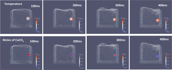
Snapshots of the limestone sphere injected into iron bath (1873 K). (Online version in color.)
Figure 3 shows the results for a 50 mol% calcined flux with a diameter of 6 mm. The decomposition of the flux started ~50 ms after its penetration in the bath, which was due to the thermal resistance of the peripheral CaO layer. The maximum penetration depths of the spheres in Figs. 2 and 3 were almost the same, suggesting that the influence of the wall on the behavior might be significant. In order to clarify the effect of the particle density change by the decomposition, a larger scale calculation with a smaller effect of the wall will be needed.

Snapshots of the 50% calcined limestone sphere injected into iron bath (1873 K). (Online version in color.)
Figure 4 shows the time variation of the residual CaCO3 mole fraction. The volume of generated CO2 gas was significantly larger (200 times or more) than that of the flux sphere when the residual CaCO3 mole fraction was reduced by 0.1. Therefore, a large amount of gas was produced in a short time, which would have generated a strong stirring effect. If CO2 was enclosed within the flux particle, the high pressure would have caused the flux particle to explode, which would have dispersed the fragments of the flux particles throughout the iron bath.
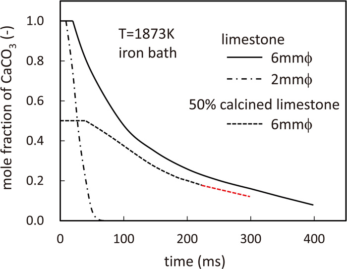
CaCO3 fraction in the flux sphere injected into iron bath (1873 K). (Online version in color.)
The same model was used for the hot metal treatment process. The temperature, density, and viscosity of the hot metal were 1573 K, 7.0 g‧cm−3, and 0.07 Pa‧s.9) The other conditions were the same as those at 1873 K.
Figure 5 shows the variation in the residual CaCO3 mole fraction over time. The behavior was similar to molten steel, but the time lag until the start of decomposition was longer because of a 200 K decrease in the temperature of the bath. It took 1.5–2 times longer to reach the same decomposition ratio as that of the molten steel bath.

CaCO3 fraction in the flux sphere injected into hot-metal bath (1573 K).
In practice, the gas phase is expected to influence the reaction between the molten iron and flux particles. Hence, the thermal resistance at the interface must be considered in the calculations. However, it is necessary to consider the effect of radiation, which increases the computational cost significantly. Therefore, instead of an exact numerical calculation, a simple estimation was performed in this study. Since the temperature of the bath was assumed to be constant, Eq. (13) was applied to the interfacial SPH particles (instead of Eq. (9)) to account for the reduced energy flux between the molten iron bath and spherical flux particles. The reduction was because of the presence of a gas phase along the spherical interface.
| (13) |
Here, f is the heat conduction impedance factor; f = 0 indicates that there is no interfacial thermal resistance. Figure 6 shows the calculation results for all cases. The decomposition time increased by a factor of 2 when the energy flux was reduced by 50% compared to the energy flux without interfacial thermal resistance. The decomposition time increased significantly (more than 10 times) when the energy flux was reduced to 10% of the energy flux without any interfacial thermal resistance. An accurate evaluation of the interfacial thermal resistance between the flux and molten iron in a practical system is a topic for future research and experimental confirmation.

Effect of the surface heat conduction impedance on the decomposition of limestone.
If the radiation heat transfer through a gas film is predominant, the energy flux may overcome the conduction heat transfer, however, the current SPH method requires a large number of particles to describe liquid-gas-solid system. The precise SPH simulation of the energy transfer will be another topic of future research.
A simulation model was developed to analyze the decomposition of limestone flux in molten iron and hot metal by coupling the heat transfer and chemical reaction phenomena with the solid-liquid two-phase flow using the SPH method. The following conclusions were obtained:
(1) A heat transfer analysis program covering heat conduction and radiation was developed using the SPH method. The program exhibited good agreement with the analytical solution.
(2) The injection of calcium carbonate spheres into the molten iron bath was simulated at 1873 K. The particle penetration behavior, temperature distribution, and mass distribution of CaCO3 were modeled over time. Because a large amount of CO2 was generated in a short time, a strong stirring effect can be expected along with the destruction of the flux particles.
(3) The calculation was performed at 1573 K for the hot metal treatment. Because of a 200 K decrease in the temperature of the iron bath, the time required for decomposition at 1573 K was 1.5–2 times greater than that at 1873 K.
(4) The effect of the interfacial thermal resistance was estimated. The decomposition time increased by a factor of 2 when the energy flux was reduced by a factor of 50%.
The authors are grateful to the JSPS Grant-in-Aid for Scientific Research Programs (Grant No. 17K06881) and the Waseda University Grant for Special Research Projects (Grant No. 2018 K-206) for financial support.