Abstract
In previous studies, we reported a cryo-annealing process consisting of subzero treatment and subsequent annealing as a novel heat treatment to overcome the low rigidity and strength caused by the coarse solidified <100> texture in super invar cast steel. In the present study, aging was added to the cryo-annealing process of Ti and Si-bearing super invar cast steels for further strengthening. By aging at 723 K after the subzero treatment, the intermetallic compounds L12–Ni3Ti and Ni3Si were finely precipitated within lenticular martensite, but not within untransformed austenite. This is because of the higher driving force for precipitation and faster atomic diffusion in the body-centered cubic matrix of martensite, as well as the high-density lattice defects that acted as preferential nucleation sites. The precipitated intermetallic compounds remained even after the matrix reverted from martensite to austenite, which led to significant strengthening of the reversed austenite. The high-strength reversed austenite contributed to the enhanced strain hardenability in the duplex structure composed of untransformed and reversed austenite, and consequently, the tensile strength was enhanced to over 800 MPa while maintaining an excellent low thermal expansion coefficient. Furthermore, an analysis of the strength mechanism based on the Orowan and Ashby-Orowan models reveals that the intermetallic compounds precipitated in reversed austenite acted as weak obstacles against dislocation motion.
1. Introduction
Super invar cast steel, which has a composition of Fe-32%Ni-5%Co (mass%), exhibits an extremely low coefficient of thermal expansion and is thus used in large-scale precision frameworks in devices for semiconductor and liquid crystal exposure and in molds for carbon fiber-reinforced plastics. However, the development of a coarse columnar austenitic structure with a <100> texture during the solidification process leads to the degradation of the Young’s modulus and strength.
To overcome this, a novel heat treatment called cryo-annealing was proposed. The treatment consists of a subzero treatment and subsequent annealing, as shown in Fig. 1.1,2) The subzero treatment partially promotes the formation of martensite, which is fully reversed into austenite by subsequent annealing above the reversion finish temperature Af (Fig. 1(a)). Because austenite reversion occurs via martensitic transformation (martensitic reversion) due to the high Ni content, the newly formed austenite contains high-density dislocations, which leads to a significant strengthening. The martensitic reversion results in the formation of an austenitic structure with the same orientation as the original austenite because of the reversibility of the crystal orientation;3,4) therefore, the low Young’s modulus cannot be improved by only martensitic reversion. However, when the annealing temperature becomes sufficiently higher than Af (Fig. 1(b)), the coarse reversed austenite becomes a randomly oriented fine-grained structure because the high-density dislocations in the reversed austenite drive recrystallization.1) As a result, the low Young’s modulus is markedly improved by recrystallization induced by martensitic reversion. Furthermore, the degradation of the Young’s modulus and strength are simultaneously suppressed by martensitic reversion after austenite recrystallization when cryo-annealing is performed twice in the sequence Fig. 1(b)→Fig. 1(a). The resulting improved super invar cast steel has a high tensile strength of over 540 MPa, which is approximately twice as large as that of non-heat treated cast steel.2) Unfortunately, further improvements in strength are required for super invar cast steel used in movable shafts and gears in ultra-precision machine tools. Therefore, it is necessary to strengthen super invar cast steel by an alternative strengthening mechanism to grain refinement strengthening and dislocation strengthening.

In previous studies, particle dispersion strengthening by carbides was investigated for strengthening super invar alloys.5,6) Considering the very slow atomic diffusion within the face-centered cubic (fcc) lattice of the austenite matrix, carbide precipitation is appropriate for particle dispersion strengthening because of the high diffusivity of interstitial carbon. However, carbon has a large influence on the thermal expansion coefficient, and the addition of even a small amount of carbon degrades the low thermal expansion coefficient of invar alloys.7) In contrast, in maraging steels that contain a large amount of Ni similarly to invar alloys, high strength is achieved by the precipitation of fine intermetallic compounds (IMCs) consisting of Ni, Ti, and Nb.8,9) The matrix of maraging steels is constituted by body-centered cubic (bcc) martensite in which atomic diffusion occurs at a much faster rate than in austenite. Considering the temporary formation of martensite during cryo-annealing, it is expected that IMCs can precipitate within the martensite and then remain within austenite after the reversion, as shown in Fig. 1(c).
In this study, the effects of aging treatment during cryo-annealing on the microstructural evolution and tensile properties of super invar cast steels bearing IMC-forming elements were investigated. In addition, the strengthening mechanism of the IMC precipitation is discussed.
2. Experimental Procedures
The super invar cast steels bearing Ti and Si (Ti-added and Si-added alloys) with the chemical compositions listed in Table 1 were used in this study. As mentioned later, to prevent a decrease in the martensitic start temperature Ms10) and increase the thermal expansion coefficient,7) only 2% Ti and 3% Si were added. These alloys were initially melted in vacuum using a 30 kg high-frequency induction heating furnace, followed by casting in a sand mold with a Y-shape. In addition, a standard super invar cast steel without Ti or Si (Base alloy) was also prepared as a comparison material. The transformation temperatures were evaluated through cryo-annealing without aging by dilatometer testing (DIL-402C, NETZECH) using cylindrical pieces (φ 6.0 mm × 25 mm) taken from the cast ingots; the start temperature Ms for the fcc-bcc martensitic transformation and the start temperature As and finish temperature Af for the bcc-fcc martensitic reversion. The transformation temperatures and volume fractions of martensite (VM) after subzero treatment are summarized in Table 1.
Table 1. Chemical compositions of three super invar alloys used in this study.
| Composition (mass%) | Ms (K) | As (K) | Af (K) | VM (%) |
|---|
| C | Si | Mn | Ni | Co | Ti | Fe |
|---|
| Ti-added alloy | 0.005 | 0.27 | 0.23 | 32.18 | 4.81 | 2.35 | Bal. | 215 | 826 | 953 | 56 |
| Si-added alloy | 0.005 | 3.25 | 0.26 | 32.39 | 4.98 | – | Bal. | 194 | 825 | 855 | 50 |
| Base alloy | 0.017 | 0.10 | 0.23 | 31.88 | 5.14 | – | Bal. | 224 | 741 | 860 | 87 |
To obtain a starting structure with a relatively fine-grained austenitic structure, cylindrical specimens with the dimensions of φ 20.0 mm × 190 mm were taken from a cast ingot that was fully recrystallized by single cryo-annealing with 1273 K annealing. These specimens were subjected to subzero treatment at 77 K in liquid nitrogen for 3.6 ks. Subsequently, the subzero-treated materials were aged at 723 K, which is below As, for 7.2 ks and then cooled in air. The subzero-treated materials were then heated to a temperature higher than Af by 20 K at a constant heating rate of 15 K/s using an induction heating machine (Fuji Electronics Industry), followed by water quenching. The heat treatment process described above is illustrated in Fig. 2.

The microstructural observations were performed using a field-emission scanning electron microscope (FE-SEM, JSM-7001F developed by JEOL) and a transmission electron microscope (TEM, JEM-2100 PLUS developed by JEOL). The FE-SEM specimens were mechanically polished with emery papers of up to #1200 and diamond abrasives. To remove the damaged layer due to the polishing, the specimens were electrolytically polished at 30 V in a mixed solution of 4% perchloric acid, 19% glycerol, and 77% ethanol. Electron backscatter diffraction (EBSD) measurements using FE-SEM were performed at an accelerating voltage of 15 kV and working distance of 15.0 mm, and the step size was set to 0.5 μm. The EBSD patterns obtained by FE-SEM were analyzed using an orientation image microscopy (OIM) package developed by TSL Solutions. The analyzed data were displayed as an inverse pole figure (IPF) map, a phase map, and a kernel average misorientation (KAM) map. In addition, quantitative chemical analysis for the element distribution in the same region as the EBSD analysis was performed by energy dispersive X-ray spectroscopy (EDS, JED-2300, JEOL). The chemical compositions of the martensite and austenite phases were analyzed at three different points chosen randomly, and the average compositions were evaluated as the mean values. Disc samples of φ 3 mm for the TEM specimens were cut from the heat-treated samples and prepared by electronic polishing with a mixed solution of 10% perchloric acid and 80% ethanol. The TEM observations were performed at an acceleration voltage of 200 kV. The hardness was evaluated using a micro Vickers hardness tester (HM-211, Mitutoyo) under a load of 1.961 N. Tensile testing was performed using an Instron testing machine (AG-X, SHIMADZU) at an initial strain rate of 1.7 × 10⁻³ s−1 using a plate test piece with a gauge volume of 1.0 × 10 × 25 mm3. The Young’s modulus was measured using a resonance frequency measuring device (JE2-RT developed by Nihon Techno-Plus Corp.) in a 2.0 × 10 × 60 mm3 sample. The thermal expansion coefficient was evaluated by dilatometry using a cylindrical piece with the dimensions of φ 6.0 mm × 25 mm in the temperature range of 273–343 K. In addition, thermodynamic calculations were performed using Thermo-Calc with the TTNI8 database.
3. Results
3.1. Precipitation of IMCs within Martensite
Figure 3 and 4 show the microstructures of Ti-added and Si-added alloys treated at 77 K, respectively. (a), (b), (c), and (d–f) in the two figures respectively show the SEM images, phase maps, IPF maps for the fcc and bcc phases, and EDS maps indicating the relative intensities of each element. The subzero treatment stimulated partial martensitic transformation. All alloys therefore exhibited mixed microstructures consisting of lenticular martensite and untransformed austenite. The EDS maps reveal that the concentrations of Ni, Ti, and Si were lower in martensite. The depletion of these elements in the dendrites during the solidification process preferentially promoted martensitic transformation along the dendrites because of the higher Ms. To quantitatively evaluate the partitioning of the elements between martensite and untransformed austenite, the average composition of each phase is listed in Table 2.

Table 2. Chemical compositions of martensite (bcc) and untransformed austenite (fcc) in subzero treated Ti- and Si-added alloys.
| Phase | Ni mass% | Ti mass% | Si mass% |
|---|
| Ti-added alloy | fcc | 33.41 | 2.59 | – |
| bcc | 29.11 | 1.38 | – |
| Si-added alloy | fcc | 36.75 | – | 4.29 |
| bcc | 28.89 | – | 2.28 |
Figure 5 shows the change in hardness during aging at 723 K after subzero treatment. The hardness of the untransformed austenite region remained unchanged even after long-term aging in all the alloys. However, the hardness of the martensite region increased rapidly over a relatively short period, and the hardness was maintained even after aging for more than 80 ks. The increase in hardness due to aging was largest in Ti-added alloy, followed by Si-added alloy, and smallest in Base alloy. This result clearly demonstrates that the addition of Ti and Si causes significant age-hardening in martensite, but not in austenite. Figure 6 shows TEM images of the untransformed austenite region in Si-added and Ti-added alloys aged at 723 K for 7.2 ks. Although a few dislocations were observed, second-phase precipitation could not be confirmed in the selected area diffraction patterns (Figs. 6(b), 6(d)). In contrast, fine particles were uniformly and densely precipitated in the martensite regions of the two alloys (Fig. 7). The precipitates have a needle-like shape with a width of 4.0 nm and length of 17.8 nm in Ti-added alloy (Fig. 7(b)), and a spherical shape with an average diameter of 3.9 nm in Si-added alloy (Fig. 7(e)). These precipitates were respectively identified as Ni3Ti and Ni3Si IMCs with the L12 crystal structure through the crystallographic analysis of the selected area diffraction patterns. In addition, it is suggested that the IMCs obey the Nishiyama-Wasserman orientation relationship ((011)α//(111)IMC, [001]α//[−101]IMC) with respect to the martensite matrix. Further TEM observations in Ti-added alloy confirmed the precipitation of Ni3Ti with the D024 crystal structure, which has been reported to be a stable IMC in maraging steels in previous research.11) Although the volume ratio of D024–Ni3Ti to L12–Ni3Ti was not analyzed accurately, these TEM observations clearly prove the high-density precipitation of IMCs within the martensite region formed by subzero treatment, which leads to significant age-hardening.

The precipitation of IMCs in the martensite region confirms that age-hardening occurred even in Base alloy, which did not contain Ti or Si. This may be because Co contained in the super invar alloy was slightly precipitated as Ni3Co. Therefore, it is suggested that Ni3Ti and Ni3Si were precipitated together with Ni3Co in Ti-added and Si-added alloys, respectively.
3.2. Austenite Reversion Accompanied by IMCs in Super Invar Cast Steel
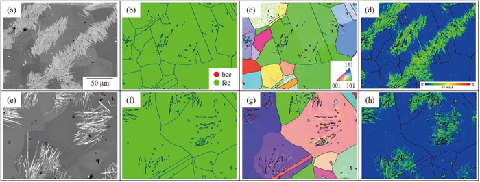
Figure 8 shows the SEM images and EBSD-based maps of (a–d) Ti-added and (e–h) Si-added alloys that were subjected to annealing after aging at 723 K for 7.2 ks, which are henceforth referred to as aging-reversion material. In the EBSD based maps, the high-angle grain boundaries with misorientations higher than 15° are indicated by black solid lines. To avoid the redissolution of IMCs after reversion, the annealing temperatures for Ti-added and Si-added alloys were selected as 973 K and 873 K, respectively, which were slightly higher than Af. In the SEM images in Figs. 8(a) and 8(e), both aging-reversion materials exhibited a mixed structure similarly to the subzero-treated materials consisted of lenticular martensite and untransformed austenite shown in Figs. 3 and 4. However, the phase maps in Figs. 8(b) and 8(f) reveal that the lenticular martensite was fully reversed to austenite by annealing. In addition, the EBSD-based images indicate that the needle-like structure in the aging-reversion materials tend to have the same orientation as the adjacent untransformed austenite (Figs. 8(c), 8(g)) and higher KAM values (Figs. 8(d), 8(h)). These are called the ghost images of lenticular martensite1,2,3,12,13,14) and are characteristic of austenite formed via martensitic reversion. Because a similar microstructure was also developed in Base alloy,1,2) it is suggested that Ni3Ti and Ni3Si precipitates within the martensite have no influence on the austenite reversion behavior.
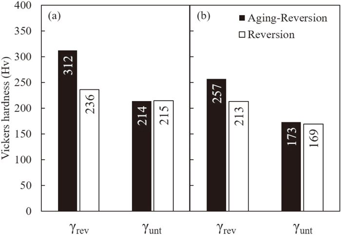
The hardness values of the reversed austenite (γrev) and untransformed austenite (γunt) in the aging-reversion Ti-added and Si-added alloy materials are shown in Fig. 9. The hardness values of the alloys annealed directly after subzero treatment without aging (i.e., reversion material) are also shown for comparison. The value of γunt remained constant regardless of aging, while that of γrev was significantly increased by aging, especially in Ti-added alloy where it increased by 70 Hv. Although the existence of IMCs had not been observed yet in the aging-reversion materials, this result strongly suggests that the IMCs, which had precipitated within the martensite region in the aging state, did not dissolve and remained within austenite even after the completion of martensitic reversion.
3.3. Tensile Properties of Super Invar Cast Steel with IMCs
To clarify the effect of aging on the mechanical properties, Fig. 10 shows the nominal stress-strain curves of aging-reversion and reversion materials in Ti-added and Si-added alloys. The curve for reversion material in Base alloy is also shown in this figure. The obtained tensile properties, 0.2% proof stress, tensile strength, and yield ratio are summarized in Table 3. It was previously confirmed that both aging-reversion materials exhibited low coefficients of thermal expansion lower than 5.0 × 10⁻⁶ K−1 and Young’s modulus larger than 150 GPa. The three reversion materials had almost the same tensile strengths of 540–600 MPa. In contrast, the tensile strength of the aging-reversion materials was dramatically higher in Ti-added and Si-added alloys, especially in Ti-added alloy where it exceeded 800 MPa. It should be noted that the yield ratio was reduced by aging in both Ti-added and Si-added alloys. The high tensile strength is therefore attributed to enhanced strain hardenability. Park et al.15) investigated the development of microscopic plastic strain partitioning between soft ferrite and hard martensite in dual-phase carbon steels using a digital image correlation technique. They reported that the yield strength of dual-phase steel is dominated by soft ferrite, while the plastic strain gradually accumulates during the work-hardening stage, even in hard martensite, and results in sufficient strain hardenability. The strain partitioning trends in the duplex microstructure suggests that the strength of untransformed and reversed austenite contributes to the 0.2% proof stress and tensile strength (strain hardening), respectively, although the strain partitioning behavior is affected by the connectivity of the duplex microstructure.16) Therefore, it can be understood that the precipitation of IMCs due to the addition of aging in the cryo-annealing process leads to the strengthening of reversed austenite and consequently contributes to the enhanced strain hardenability and tensile strength in super invar cast steel.

Table 3. Tensile properties of Ti- and Si-added alloys and Base alloy after cryo-annealing with and without aging at 723 K for 7.2 ks.
| Material | Process | 0.2% proof stress (MPa) | Tensile strength (MPa) | Yield ratio |
|---|
| Ti-added alloy | Aging-Reversion | 516 | 822 | 0.63 |
| Reversion | 442 | 607 | 0.73 |
| Si-added alloy | Aging-Reversion | 366 | 671 | 0.55 |
| Reversion | 332 | 555 | 0.60 |
| Base alloy | Reversion | 394 | 544 | 0.72 |
4. Discussion
4.1. Behavior of IMCs Precipitation in the Martensite and Austenite Phases
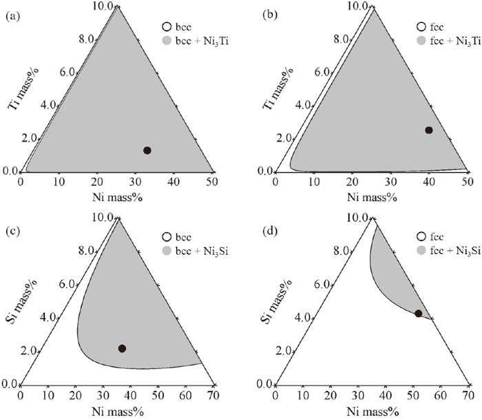
Figure 11 shows the Fe-rich region of the ternary isothermal phase diagrams of (a, b) the Fe–Ni–Ti system, and those of (c, d) the Fe–Ni–Si systems at 723 K calculated by Thermo-Calc. In this figure, the phase equilibria of L12–Ni3Ti or Ni3Si in the bcc (Figs. 11(a), 11(c)) and (Figs. 11(b), 11(d)) fcc matrices are shown for each system. Here, the black circles in each phase diagram indicate the average compositions of the martensite and untransformed austenite matrices, as shown in Table 2. Each phase diagram therefore indicates the equilibrium state in the martensite and untransformed austenite regions at the aging temperature under the assumption that there is no significant macroscopic diffusion of elements between the two regions. Comparing the phase diagrams for each alloy system (Figs. 11(a)–11(b); Figs. 11(c)–11(d)), it can be seen that the solubility of the IMCs in martensite is much smaller than that in austenite. This suggest that the driving force for the precipitation of IMCs is higher in the martensite region. Furthermore, a larger volume of L12–Ni3Ti might be precipitated compared with L12–Ni3Si in the martensite region because the solubility of L12–Ni3Ti is markedly limited. Meanwhile, looking the solubility of the IMCs in the austenite region, the average composition is surely in the two-phase region of austenite and IMCs, especially in the Fe–Ni–Ti system. This means that the IMCs are in the super-saturated state not only within martensite but also within the austenite region, although the lower precipitation driving force in the latter. In general, the diffusion of solute atoms is significantly slower in fcc matrices compared to bcc matrices.17) Considering the absence of IMC precipitation in the austenite region in the experimental results (see Figs. 5 and 6), it is thought that the precipitation of IMCs was kinetically restricted. In addition, the existence of high-density lattice defects such as dislocations and twin interfaces in the martensite region may be promoted the nucleation of IMCs. From these results, it can be concluded that subzero treatment associated with bcc-martensite formation was required for the precipitation of IMCs in super invar cast steel.
The strengthening mechanism of the reversed austenite by IMCs are discussed. When dislocation motion on a slip plane is inhibited by fine dispersed particles that act as strong obstacles, the increment of applied stress for dislocation motion is discussed based on the Orowan and Ashby-Orowan mechanisms.18,19,20) They is fundamentally described by ΔσOR and ΔσAS-OR, respectively, which are given by the following equations:20)
|
Δ
σ
AS-OR
=
0.8Mμb
2π
1-ν
L
ln(
d
2b
)
| (2) |
where
M,
μ,
b,
ν,
L, and
d are the Taylor factor, shear modulus, Burgers vector, Poisson’s ratio of the matrix, average spacing between two particles, and particle diameter on the slip plane, respectively. The average value of
M is 3.06 in fcc metals with random textures, and the values of 55.8 GPa, 0.353 nm, and 0.29 for invar alloy were used for
μ,
b, and
ν, respectively.
21) L and
d can be calculated from the particle radius
r and volume fraction
f as follows assuming randomly distributed spherical particles:
|
L
=
2
3
(
π
f
-2
)
r,
| (3) |
Assuming that the IMCs hardly dissolve within the austenite matrix during the annealing process, the values of f of the IMCs were measured by TEM observation (Fig. 7). Assuming spherical particles, the values of r were calculated from f and number density of the IMCs. Those values were substituted into the Eqs. (3) and (4). The resulting particle dispersion strengthening estimated using Eqs. (1) and (2) were ΔσOR = 2296 MPa and ΔσAS-OR = 894 MPa for Ti-added alloy, and ΔσOR = 1996 MPa and ΔσAS-OR = 694 MPa for Si-added alloy. The relationship between the strength σ (MPa) and Vickers hardness Hv was established using the following empirical formula:22)
When the particle dispersion strengthening ΔσAS-OR was converted into the Vickers hardness using Eq. (5), the increase in hardness in Ti -and Si-added alloys were 275 Hv and 215 Hv, respectively. However, the increase in the hardness of reversed austenite γrev due to the precipitation of IMCs was 44–76 Hv (see Fig. 9), which was much lower than expected. This suggests that the IMCs in reversed austenite act as weak obstacles against dislocation motion and are sheared by dislocations in the so-called cutting mechanism. If the cutting behavior is solely dependent on the shear strength τ* of the particles without considering the effects of coherent strain around the particles, the differences in the shear modulus between the particles and the matrix, and the interfacial energy of the particles in the sheared plane, the critical particle diameter d* for cutting can be estimated as:19)
where
β is the line tension coefficient of dislocation and was assumed to be 0.3.
23) Takaki
19) proposed that
τ* can be estimated from the hardness and is approximately 1/3 of the strength converted from the hardness using
Eq. (5). Using this proposal,
τ* was estimated to be 1183 MPa and 552 MPa from the hardness of Ni
3Ti (1070 Hv
24)) and Ni
3Si (500 Hv
25)), respectively. By substituting these values into
Eq. (6), the
d* of Ni
3Ti and Ni
3Si were calculated to be 7.2 nm and 15.4 nm, respectively. From the TEM observations, the particle width of Ni
3Ti was 4 nm, and the average particle diameter of Ni
3Si was 3.9 nm, which is smaller than
d*. Therefore, it is expected that these precipitates were sheared by dislocations, even if these IMCs hardly dissolved after austenite reversion. The age-hardening behavior (
Fig. 5) reveals that the hardness of the martensite region was significantly increased at the early stage of aging, and the peak hardness was maintained even after long-period aging. In other words, it may be difficult for the IMCs to become coarser because of their high thermal stability, and thus, the volume fraction and shear stress are important factors for precipitation strengthening by IMCs. The higher the shear strength and volume fraction of the IMC precipitates, the higher is the tensile strength of super invar cast steel. From this consideration, Ni
3Ti is a good candidate for a high tensile-strength steel because its solubility in martensite is smaller and its shear strength seems to be higher compared with Ni
3Si. In addition to the IMCs, attention should be paid to the volume fraction of reversed austenite. As shown in
Figs. 3,
4, and
8, the volume fraction and distribution of reversed austenite are greatly affected by the segregation behavior during the solidification process. Therefore, to optimize the mechanical properties of super invar cast steel, it is important to control the precipitation of IMCs in the consideration of solidifying segregation.
5. Conclusion
To develop high-strength super invar cast steel by IMC precipitation, the microstructural evolution and corresponding tensile properties during cryo-annealing with aging were investigated in Ti-added and Si-added alloys. The following conclusions were obtained:
(1) When the duplex structure consisting of lenticular martensite and untransformed austenite phase formed by subzero treatment is aged at 723 K, IMCs (Ni3Ti and Ni3Si) are finely precipitated only within martensite, which results in remarkable age-hardening. The preferential precipitation of IMCs in martensite is caused by the large precipitation driving force, fast diffusion kinetics, and high-density lattice defects that act as preferential nucleation sites.
(2) Even after the aged martensite is reversed to austenite by subsequent annealing, the IMCs remain within the reversed austenite. The strengthening of the reversed austenite by IMC precipitation enhances the strain hardenability of the duplex austenitic steel and leads to a significant increase in tensile strength.
(3) The particle dispersion strengthening due to IMCs precipitation estimated by the Orowan and Ashby-Orowan mechanisms is much higher than that obtained in the experimental results. This suggests that the IMCs in the reversed austenite act as weak obstacles against dislocation motion and are sheared by dislocations.
References
- 1) N. Sakaguchi, K. Ona, R. Bao and N. Nakada: ISIJ Int., 60 (2020), 2609. https://doi.org/10.2355/isijinternational.ISIJINT-2020-254
- 2) N. Sakaguchi, H. Ohno and N. Nakada: ISIJ Int., 62 (2022), 586. https://doi.org/10.2355/isijinternational.ISIJINT-2021-478
- 3) G. Krauss, Jr.: Sc.D. thesis, Massachusetts Institute of Technology, (1961), http://hdl.handle.net/1721.1/11317, (accessed 2020-12-07).
- 4) N. Nakada: Mater. Lett., 187 (2017), 166. https://doi.org/10.1016/j.matlet.2016.10.056
- 5) K. Nakama: Ph.D. thesis, Kyoto University, (2014), https://doi.org/10.14989/doctor.k18276, (accessed 2020-04-06) (in Japanese).
- 6) H. Liu, Z. Sun, G. Wang, X. Sun, J. Li, F. Xue, H. Peng and Y. Zhang: Mater. Sci. Eng. A, 654 (2016), 107. https://doi.org/10.1016/j.msea.2015.12.018
- 7) M. Tsuda: Tetsu-to-Hagané, 80 (1994), 944 (in Japanese). https://doi.org/10.2355/tetsutohagane1955.80.12_944
- 8) R. F. Decker, J. T. Eash and A. J. Goldman: Trans. Am. Soc. Met., 55 (1962), 58.
- 9) S. Floreen: Trans. Am. Soc. Met., 57 (1964), 38.
- 10) K. Ishida and T. Nishizawa: Trans. Jpn. Inst. Met., 15 (1974), 217. https://doi.org/10.2320/matertrans1960.15.217
- 11) Y.-U. Heo, M. Takeguchi, K. Furuya and H.-C. Lee: Acta Mater., 57 (2009), 1176. https://doi.org/10.1016/j.actamat.2008.10.056
- 12) B. Hyatt and G. Krauss: Trans. Am. Soc. Met., 61 (1968), 168.
- 13) T. Maki, S. Nakagawa and I. Tamura: J. Jpn. Inst. Met., 44 (1980), 1164 (in Japanese). https://doi.org/10.2320/jinstmet1952.44.10_1164
- 14) B. Rui, N. Sakaguchi and N. Nakada: Materialia, 15 (2021), 100995. https://doi.org/10.1016/j.mtla.2020.100995
- 15) K. Park, M. Nishiyama, N. Nakada, T. Tsuchiyama and S. Takaki: Mater. Sci. Eng. A, 604 (2014), 135. https://doi.org/10.1016/j.msea.2014.02.058
- 16) N. Nakada, S. Kawasaki, Y. Kogakura, T. Tsuchiyama and S. Takaki: Mater. Sci. Eng. A, 690 (2017), 270. https://doi.org/10.1016/j.msea.2017.03.002
- 17) H. Oikawa: Tetsu-to-Hagané, 68 (1982), 1489 (in Japanese). https://doi.org/10.2355/tetsutohagane1955.68.10_1489
- 18) L. M. Brown: Strength of Metals and Alloys, Proc. 5th Int. Conf., (Aachen), ed. by P. Haasen et al., Pergamon Press, Oxford, UK, (1980), 1551.
- 19) S. Takaki: Bull. Iron Steel Inst. Jpn., 25 (2020), 277 (in Japanese).
- 20) N. Kamikawa, Y. Abe, G. Miyamoto, Y. Funakawa and T. Furuhara: ISIJ Int., 54 (2014), 212. https://doi.org/10.2355/isijinternational.54.212
- 21) W. S. McCain and R. E. Maringer: Mechanical and Physical Properties of Invar and Invar-type Alloys, Battelle Memorial Institute, Defense Metals Information Center, Columbus, OH, (1965), 46.
- 22) N. Hasegawa, J. Arai and T. Tanaka: J. Soc. Mater. Sci., Jpn., 39 (1990), 859 (in Japanese). https://doi.org/10.2472/jsms.39.859
- 23) S. Takaki and T. Tsuchiyama: Tetsu-to-Hagané, 104 (2018), 117 (in Japanese). https://doi.org/10.2355/tetsutohagane.TETSU-2017-053
- 24) V. Hoppe, A. Gibas, W. Grzegorczyk, M. Małecki and M. Hasiak: Interdiscip. J. Eng. Sci., 7 (2019), 1.
- 25) N. Hiraishi and K. Asabe: J. Jpn. Soc. Powder Powder Metall., 40 (1993), 947 (in Japanese). https://doi.org/10.2497/jjspm.40.947