Abstract
This study examined the fatigue crack propagation (FCP) behavior of three kinds of zero thermal expansion (ZTE) alloys. The specimens were manufactured by one of three processes, (casting, forging, and laser additive manufacturing: selective laser melting (SLM)). The FCP rates in the casted alloy were similar to SS400, which was used for comparison. In the SLM product, the FCP rates were higher than the casted alloy and slightly higher than forged alloy, particularly in the low ΔK region. The fracture surfaces were examined by scanning electron microscopy. A rough crack surface was observed in the casted alloy, but small marks along the crack propagation direction were observed in the SLM specimen. The crack opening load was measured to estimate the FCP behavior and consider the effective stress intensity factor range. In an evaluation by the effective stress intensity factor range, the FCP rates of the specimens produced using the three manufacturing processes were similar. Overall, the ZTE alloy manufactured by SLM showed good FCP behavior compared to the forged alloy. The difference in the results between the two products was attributed to the difference in the fracture surface due to the different microstructures.
1. Introduction
In the aerospace field, high accuracy and dimensional stability (low thermal expansion characteristics) are essential in structural products, including optical facilities and sensor stands, which are used in severe environments.1) For this reason, low thermal expansion alloys have attracted considerable attention as materials that suppress the deterioration of accuracy accompanying the thermal deformation of metal alloy products. Development has been carried out in pursuing alloys with a zero thermal expansion (ZTE) coefficient.2) The application of this type of alloy to precision mechanical equipment is progressing, and the importance of strength and other mechanical characteristics is also increasing.3)
As “additional processing,” additive manufacturing technology of alloy materials has been called the third processing method after “cutting technology” by machining and related techniques and “forming technology,” such as casting, forging, and press forming. Additive manufacturing is now applied in an increasing number of cases, firstly because it is possible to produce parts with shapes that cannot be obtained by conventional processes, and also because shortening of the delivery times when manufacturing products with complex shapes are also expected accompanying progress in process digitalization.4) Since practical metal 3D printers became available, it has become possible to use a diverse range of feedstock materials. The mechanical properties of additive-manufactured materials have been evaluated. Additive manufacturing is also suitable because aerospace parts are multi-type, small-lot products.5) On the other hand, equipment maintenance is frequently difficult or impossible in aerospace applications. Therefore, it is essential to evaluate the fatigue characteristics of structural members that will be subjected to fluctuating loads. With the development of 3D printers equipped with a Yb fiber laser, with a higher output and higher brightness than conventional 3D printers using a carbon dioxide laser, it has become possible to produce materials with static strength and elastic properties equal to those of products manufactured by casting and forging.6) However, there has been insufficient research on the FCP characteristics of materials formed by metal 3D printers.7) In particular, no studies have evaluated low thermal expansion materials or other high-performance materials.
The present research examined the FCP characteristics of extremely low thermal expansion materials (hereinafter called ultra-low thermal expansion materials). In addition, the differences in the FCP behavior due to differences in the manufacturing process (i.e., casting, forging or additive manufacturing) are clarified and discussed from the viewpoint of the crack opening and closure behavior.
2. Experimental
2.1. Test Material and Specimens
The test materials were casted, forged, or additive-manufactured products fabricated by selective laser melting (SLM) using an ultra-low thermal expansion alloy developed by Nippon Chuzo K.K. The SLM product was produced using a 3D printer (EOS M290, manufactured by EOS GmbH, Germany) equipped with a 400 W output class Yb fiber laser (beam spot diameter: approx. 0.1 mm). The test powder was an ultra-low thermal expansion alloy powder with a particle diameter of 10–45 μm, which is suitable for SLM. This powder was produced using the nitrogen gas atomizing method in air. In the laser scanning direction, printing was performed by rotating each layer by 67°, according to the method reported by Kimura et al.6) In this connection, anisotropic crack propagation behavior was observed in Inconel 718 produced by additive manufacturing when the laser scanning direction was rotated by 90° for each layer.7)
Table 1 lists the chemical composition of the ultra-low thermal expansion alloy used in this research and an example of the chemical composition of a powder for use in additive manufacturing. Table 2 presents the mechanical material properties of the test specimens prepared by each process when tested in accordance with JIS Z 2241.8) The forged product was press-forged uniformly from four directions. The basic static mechanical properties of the material prepared by additive manufacturing technology (SLM) were investigated. The material characteristics were similar to the forged product.8) The results for a rolled steel for general structural use (hereinafter, SS400) were used as a comparison because the elongation and reduction of the area of all the materials prepared in this experiment were significant in the static tensile test. SS400 was selected for comparison because it is a general steel material with similar ductility to that of the ultra-low thermal expansion alloy, while it is also a material with an ordinary thermal expansion coefficient. Therefore, it is possible to link with research comparing SS400 with other materials by comparing the crack propagation characteristics of the test materials in this study and this representative steel material.
Table 1. Chemical composition of ZTE alloy (mass%).
| C | Si | Mn | Ni | Co | Fe |
|---|
| SLM powder | 0.001 | 0.01 | 0.01 | 33.1 | 4.2 | balance |
Table 2. Mechanical properties of ZTE alloy.
8)| Process | Tensile strength MPa | 0.2% proof stress MPa | Elongation % | Reduction of area % | Young’s modulus GPa |
|---|
| SLM | 479 | 323 | 45 | 82 | 131 |
| Casting | 372 | 265 | 28 | 61 | 121 |
| Forging | 487 | 334 | 39 | 75 | 133 |
Test method: JIS Z2241 proportional test piece
original gage length Lo = 60 mm, diameter d0 = 10 mm
Figure 1 presents optical microscopy images of the microstructures of the test materials prepared by casting, forging, and additive manufacturing used in this experiment (hereinafter referred to as the casted product, forged product, and SLM product, respectively). After polishing the surface, etching with a dilute HF solution was performed to observe these specimens. The microstructures were then observed by optical microscopy. From the observation images, a dendritic structure was observed in the casted product, while twin crystals were confirmed in the forged product. When the specimen prepared by SLM was observed from the building direction (z direction), as observed previously,9,10) melt pools in the building direction (z direction) were observed in the xz and yz planes. Moreover, granular isotropic organization was observed in the xy plane, as observed from the building direction. Hence, matrix directional dependency (i.e., anisotropy) was confirmed. However, no defects, such as voids or inclusions, were found in the matrix of the built material at the magnification used.

Test specimens used in the FCP test (CT specimens) with the geometry shown in Fig. 2 were prepared by wire electric discharge machining. The specimen thickness t was 10.0 mm, 11.54 mm, and 6.73 mm for the casted, forged product, and SLM products, respectively. A strain gage was attached to the back of the specimens to monitor the state of crack opening and closure during the FCP test. The specimen of the SLM material was built in the sheet thickness direction, as illustrated in Fig. 3.
2.2. Experimental Method
A FCP test was conducted in the atmosphere (air) at room temperature using an electrohydraulic servocontrol fatigue test machine (Servopulser, manufactured by Shimadzu Corporation, Japan; capacity: 100 kN) under the following test conditions: a stress ratio R = 0.05 and repeat speed f = 20 Hz. The stress intensity factor (K) was calculated using the Srawley’s equation,11) as shown below:
|
F=(
(
2+ξ
)
/
(
1-ξ
)
3/2
)
×(
0.886+4.64ξ-13.32
ξ
2
+14.72
ξ
3
-5.6
ξ
4
)
|
where,
ξ =
a/
W (
a: crack length,
t: sheet thickness,
W: sheet width)
In this experiment, a fatigue load of ΔK=2.0 MPa
m
, f = 20 Hz was applied to the specimens, and crack initiation was checked at intervals of N = 1000 cycles. A pre-crack was judged to have been introduced when crack initiation was confirmed on both sides of the specimen. After introducing the pre-crack, the fatigue load was applied with ΔK reduced by 0.1 MPa
m
, and a load was applied with ΔK reduced by an additional 0.1 MPa
m
when crack propagation was detected. The value of ΔK when crack propagation could not be observed at N = 20000 cycles was taken as the crack propagation lower limit value ΔKth. The FCP was started by increasing ΔK by 0.1 MPa
m
after which a cyclic load was applied at a constant value. The crack length was measured using the replica method at intervals of a set number of cycles (N = 2000–5000), and the crack propagation speed da/dN at ΔK during the experiment was obtained by dividing the increase in crack length growth da by the number of cycles dN up to that point. After fracture, the fracture surface was observed by scanning electron microscopy (SEM), and the relationship between the fracture surface and the crack propagation speed, and ΔK was discussed. Subsequently, the crack opening point was determined using the unloading elastic compliance method, and was arranged into ΔKeff and discussed.
3. Experimental Results and Discussion
3.1. Crack Propagation Characteristics
Figure 4 compares the crack propagation test results for the specimen prepared by casting and the results for SS400 obtained experimentally, as expressed by the da/dN–ΔK curve. From this figure, when ΔK was reduced to approximately 2.0 MPa
m
, the crack propagation rate was lower than the linear relationship da/dN vs. ΔK observed in ΔK > 2.0 MPa
m
. The threshold value for crack propagation ΔKth was close to this value. These tendencies were common in the two materials. The crack propagation characteristics obtained with the casted product of the ultra-low thermal expansion alloy were similar to those of SS400, even though ΔK was on the high-speed side in the region above 10 MPa
m
. The lower limit stress intensity factors were ΔKth= 2.0 MPa
m
for SS400 and ΔKth=1.8 MPa
m
for the casted product. The exponent m12) given by the Paris law in the IIb region (da/dN = CΔKm) was m = 2.0 for the SS400 specimen and m = 2.6 for the casted specimen, with SS400 displaying a smaller value.
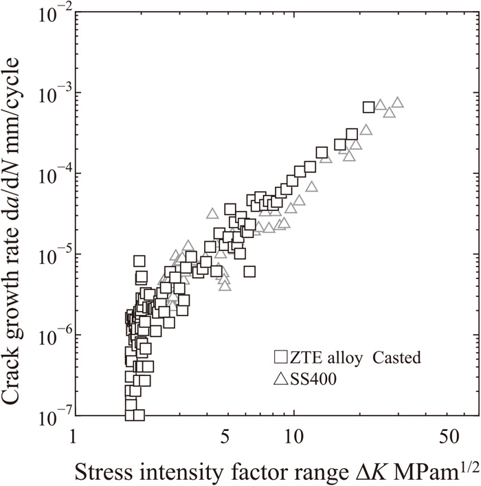
Figure 5 presents the crack propagation results of the casted, forged, and SLM products of the ultra-low thermal expansion alloy expressed by the da/dN - ΔK curve. The crack propagation speeds of the forged and SLM products were both on the higher speed side than the casted material in the low ΔK region. A comparison of the forged product with the SLM product showed that the SLM product tended to have a faster crack propagation speed in the region where ΔK=2.0–5.0 MPa
m
. The lower limit stress intensity factors were ΔKth=2.0 MPa
m
for the forged product and ΔKth=1.6 MPa
m
for the SLM product. Based on these facts, crack propagation occurs at a smaller ΔK in the SLM product compared to the other manufacturing processes. The exponent m of the Paris law in the region where the increase in the crack propagation speed was constant was m = 1.8 for the forged product and m = 1.6 for the SLM product, which was smaller than the m value of the casted product in both cases.
3.2. Crack Shape
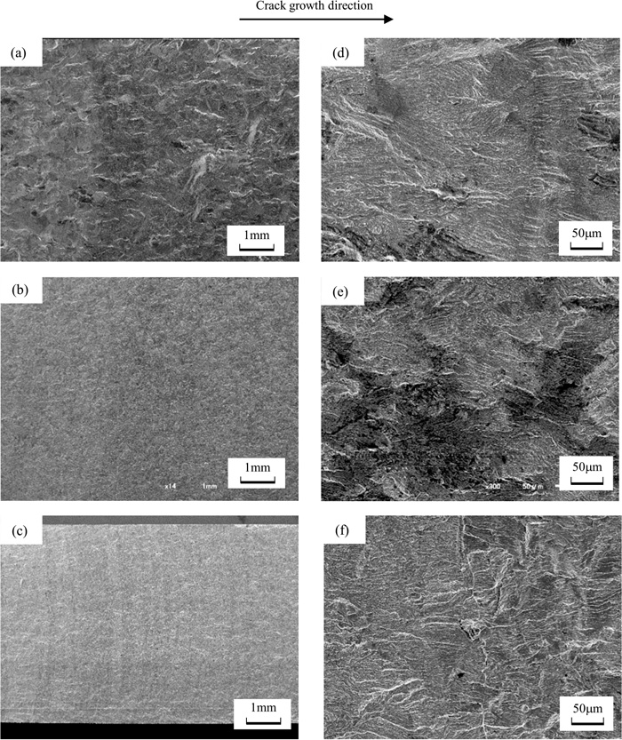
One probable cause of the difference in the crack propagation characteristics observed in the previous section was a difference in the shape (curvature) of the crack path. Figure 6 presents the optical microscopy observations of the crack paths of ΔK ≈ 2.5 MPa
m
in the specimens before fracture. The results suggest that the propagation path of the crack in the casted product was much more curved than the products of the other manufacturing processes. Therefore, the fracture surfaces of the fractured specimens prepared by each manufacturing process were observed by SEM (Fig. 7). First, the low magnification observation showed that unevenness of the fracture surface of the casted product was remarkable compared to the other manufacturing processes. This is a distinctive feature of the casted product, as shown in Fig. 6. The other two types of specimens displayed smooth crack surfaces. In addition, a thin vertical stripe pattern perpendicular to the crack propagation direction could be seen, particularly in the SLM product. Similar propagation occurred in all parts of the crack, without bias at any particular part. From the high magnification images, the casted and forged products displayed uneven fracture surfaces, while the fracture surface of the SLM product was comparatively smooth and had the distinctive feature of a linear step-like formation along the crack propagation direction. The three test materials each had unique crack (fracture) surface features. In addition, no defects in the matrix were observed in the observation of the fracture surface.

From the load-strain curves obtained from an investigation of the relationship between the load and the strain measured by a strain gage attached to the back of the test piece, an inflection point could be observed in the load-strain curves under many conditions. As one example, Fig. 8 shows the load-strain curve of the casted product at ΔK=1.94 MPa
m
. The inflection point observed in this figure indicated the load Pop at which crack opening occurs, i.e., the crack opening point, while loads lower than Pop represent the crack closure range, where a crack does not open. Figure 9 shows the relationship between the load ratio Pop/Pmax (ratio of the crack opening load Pop to the maximum load Pmax) and the change of the stress intensity factor ΔK for the three test materials and the comparison material SS400. The specimens showed comparatively large load ratios in the initial period of the test, after which Pop/Pmax decreased gradually and reached 10% or less when ΔK exceeded 10 MPa
m
. Moreover, the figure also showed that SS400 and the casted product have higher ratios of the crack opening load Pop to the total load Pmax in the region where ΔK does not exceed 10 MPa
m
compared to the other ultra-low thermal expansion alloy products. This means that crack opening is difficult in SS400 and the casted product. Even under the same load, it is predicted that that load will not act effectively in crack propagation in compared to the forging and SLM products. Crack opening and closing also include crack closure induced by plastic deformation, in addition to crack closure induced by the fracture surface roughness.13) Therefore, it is necessary to consider the crack opening and closure behavior based on the differences due to the manufacturing processes of the materials used in this experiment. Regarding crack closure induced by plastic deformation, the possibility that this may affect the crack opening and closing characteristics of the casted product is conceivable because the plastic deformation region was large in the casted product, which has a low Young’s modulus or 0.2% proof stress (Table 2). However, the material properties of the forged product and SLM product were similar to those of the casted product. Hence, it is reasonable to think that the region of plastic deformation is similar. Accordingly, crack closure induced by fracture surface roughness will be considered.

The smoothness of the crack (fracture) surfaces shown in Figs. 6 and 7 affects the crack opening load ratio Pop/Pmax. Pop/Pmax decreased in the order of casted product, forged product, and SLM product (Fig. 9). In particular, in the SLM product, Pop/Pmax decreased to approximately 10% from ΔK ≈ 3.0 MPa
m
, suggesting that the linear step-like formation along the direction of crack growth did not become an obstacle to crack opening, which was observed in Fig. 6(e). Hence, a crack surface with comparatively smooth crack opening and closing is formed because the interfaces between the layers of the built SLM product shown by the dashed lines in Fig. 3 do not cross the growth direction (x direction) of the crack.
Next, the effective stress intensity factor range ΔKeff considering the crack opening point obtained by the unloading elastic compliance method14) in Chapter 2 was calculated, and its relationship with the crack propagation speed is expressed by the da/dN-ΔKeff curve, as shown in Fig. 10. When the effective stress intensity factor range ΔKeff was considered, the results for the forged product and the SLM product showed better agreement with near ΔK=2.0 MPa
m
than the results in Fig. 5, where ΔKeff was not considered. The crack opening point of the forged product was higher than the opening point of the SLM product (Fig. 9), but good agreement was observed between the da/dN-ΔKeff curves shown in Fig. 10 when the difference between the two crack opening points was considered. Similarly, the exponent m of the Paris law in the range where the increase in crack propagation speed is constant was m = 1.6 for both the forged product and SLM products, showing good agreement between the two products. Furthermore, the exponent obtained for the casted product was m = 1.7. Its crack propagation characteristics were also similar to those of the materials prepared by the other manufacturing processes when the crack opening and closing behaviors were considered. For SS400, this difference may originate from the differences in the material properties of the SS400 and the ultra-low thermal expansion alloy materials (e.g., differences in the plastic region formed in front of the crack due to differences in the Young’s modulus and the yield point) because m = 1.4 and this material is generally on the low speed side. From the results up to this point, the FCP behavior of the ultra-low thermal expansion alloys differs according to their manufacturing processes, and the crack propagation speed of the forged product and SLM product is faster than that of the casted material. On the other hand, the possibility that this difference originates from the characteristics of the crack surface due to differences in the matrix was suggested. Compared to the forged product, the crack propagation speed of the additive-manufactured material produced using a 3D printer was on the slightly high side when crack opening and closing behavior was not considered. However, this difference was attributed to the smooth fracture surface of the material produced by additive manufacturing, and not defects in the matrix. Nevertheless, it is unclear if the FCP behavior of the SLM product used in this study was inferior to that of the forged material because there was no obvious anisotropy or defects observed on the crack surface, and the difference in the crack propagation rate with the forged product was also slight. Thus, this product has reached a stage where it can be actively used with confidence. However, the lower limit stress intensity factor of ΔKth=1.6 MPa
m
of the object built with the 3D printer was lower than that obtained with the other manufacturing processes. Experiments with additive-manufactured products using test specimens prepared using other building directions will also be conducted in future experiments.

4. Conclusion
Test specimens were prepared from casted, forged, and SLM products using an ultra-low thermal expansion alloy. The crack propagation behavior was examined by conducting FCP tests using these specimens. The results obtained are summarized below.
(1) The crack propagation characteristics of the casted product were similar to those of SS400.
(2) Compared to the crack propagation characteristics of the casted product, the crack propagation characteristics of the forged product were on the high crack propagation speed side in the low ΔK region.
(3) The crack propagation characteristics of the SLM product were slight faster than those of the forged product.
(4) The fracture surface of the test specimen prepared by casting displayed considerable roughness, while the fracture surface of the SLM product showed a linear step-like formation oriented along the direction of crack growth.
(5) The ratio of the crack opening load to the maximum load increased in the order of the SLM product, forged product, and casted product. The largest ratio was obtained with SS400 used as a comparison material.
(6) The crack opening and closing behavior was considered in terms of the effective stress intensity factor range ΔKeff, the crack propagation speed-ΔKeff relationships of the materials prepared by the various manufacturing processes were similar but the casted product showed lower rates in the smaller ΔK region.
Acknowledgment
In carrying out this research, the authors received cooperation in the experiments from Mr. Toshiki Ue of Toyoda Iron Works Co., Ltd. and Mr. Takuma Arimoto of the Toyota Technological Institute Graduate School. The authors also received guidance from Mr. Masaki Nakajima in preparing the manuscript. The authors wish to express their appreciation to all concerned for their valuable assistance.
References
- 1) S. F. Jacobs: Opt. Acta, 33 (1986), 1377. https://doi.org/10.1080/713821886
- 2) T. Handa and N. Kurusu: Sokeizai, 55 (2014), 28 (in Japanese).
- 3) M. Kishida and T. Masumoto: Materia Jpn., 36 (1997), 1080 (in Japanese). https://doi.org/10.2320/materia.36.1080
- 4) H. Kyogoku and T.-T. Ikeshoji: Mech. Eng. Rev., 7 (2020), 19-00182. https://doi.org/10.1299/mer.19-00182
- 5) H. Ikeda and T. Masuoka: J. Jpn. Soc. Precis. Eng., 82 (2016), 639 (in Japanese). https://doi.org/10.2493/jjspe.82.639
- 6) T. Kimura and T. Nakamoto: J. Jpn. Inst. Light Met., 66 (2016), 167 (in Japanese). https://doi.org/10.2464/jilm.66.167
- 7) J. Denny, A. N. Jinoop, C. P. Paul, R. Singh and K. S. Bindra: Mater. Lett., 276 (2020), 128241. https://doi.org/10.1016/j.matlet.2020.128241
- 8) N. Oyama, K. Kitamoto, T. Handa and M. Asahina: Proc. SPIE, 11451 (2020), 1145116. https://doi.org/10.1117/12.2560758
- 9) H. Choo, K.-L. Sham, J. Bohling, A. Ngo, X. Xiao, Y. Ren, P. J. Depond, M. J. Matthews and E. Garlea: Mater. Des., 164 (2019), 107534. https://doi.org/10.1016/j.matdes.2018.12.006
- 10) T. M. Rodgers, J. D. Madison and V. Tikare: Comput. Mater. Sci., 135 (2017), 78. https://doi.org/10.1016/j.commatsci.2017.03.053
- 11) J. E. Srawley: Int. J. Fract., 12 (1976), 475. https://doi.org/10.1007/BF00032844
- 12) P. Paris and F. Erdogan: J. Basic Eng., 85 (1963), 528. https://doi.org/10.1115/1.3656900
- 13) H. Kobayashi: Trans. Jpn. Soc. Mech. Eng. A, 49 (1983), 771 (in Japanese). https://doi.org/10.1299/kikaia.49.771
- 14) M. Kikukawa, M. Jono, K. Tanaka and M. Takatani: J. Soc. Mater. Sci., Jpn., 25 (1976), 899. https://doi.org/10.2472/jsms.25.899