Abstract
Tensile shear test specimens were fabricated by a resistance spot welding (RSW) procedure using electrodes with two different tip diameters. The tip diameter was changed to adjust the corona bond length with keeping the nugget sizes the same. Furthermore, the nugget sizes were changed by controlling the welding process parameters, resulting in the nugget sizes of 3√t, 4√t and 4.7√t, where t was the sheet thickness. Microstructural analyses revealed that the corona bond length increased with increasing tip diameter at a given nugget size. Subsequently, tensile shear static and fatigue tests were conducted to investigate the effects of corona bond lengths and nugget sizes on the mechanical properties of the welds. The tip diameter had little effect on the tensile strength of the welds, while the strength increased with increasing nugget size and the strength level of steel sheet. However, the effects of the tip diameters, nugget sizes and strength levels of steel sheets on the fatigue strengths were hardly seen. That was because the fatigue crack propagation life was dominant in the total fatigue life of the welds. Under fatigue loading condition, fatigue crack tended to grow along the corona bond, which could be attributed to the lower bonding strength along the corona bond in the high strength steel. However, the fatigue crack propagation life along the corona bond was negligible in comparison with the total fatigue life.
1. Introduction
In the field of the automobile industry, there is a strong demand for weight reduction of the vehicle body structures from the viewpoint of improving fuel efficiency. Therefore, light-weight materials such as aluminum or magnesium alloys are attractive for weight reduction. However, high impact resistance is highly required for car bodies to ensure the safety in the collision accidents. Therefore, high rigidity and high strength are also important selection factors for the materials of car bodies. Because of the lower absolute strengths of light-weight alloys, high strength steel sheets have been increasingly used for automobiles to meet the demands of weight reduction and high impact resistance. Therefore, resistance spot welding (RSW) has been widely used for the joining of mild, high-strength and ultra-high-strength steel sheets including galvanized ones.1,2,3) Furthermore, RSW can even join dissimilar alloys such as steel and aluminum alloy.4,5,6) To use RSW joints for car bodies, fatigue properties of the joints should be evaluated, thus many studies on the fatigue strength of RSW joints have been conducted7,8,9,10,11,12,13,14,15,16,17) including ultra-high-strength steels. In those studies, it has been reported that the static tensile shear strength of RSW joint increased with increasing yield strength of steel, while fatigue strength was insensitive to the yield strength of steel. In addition, the fatigue strength of RSW joints is as good as or slightly lower than that of laser spot welds.18) In some reports,19,20) fracture mechanics parameter, namely stress intensity factor, of the crack around the nugget was numerically calculated to predict fatigue lives of RSW joints. Wu et al.20) successfully predicted fatigue lives based on the crack propagation rates, while predicted lives were slightly longer than the experimental ones. Non-destructive observation of a real fatigue crack shape around the nugget21) will be able to contribute to the better prediction method in the future.
In our previous study,22) the effects of nugget sizes and strength levels of steels on the tensile properties of RSW joints were investigated using tensile shear specimens under monotonic and fatigue loading conditions. It has been reported that the tensile strength under monotonic loading condition linearly increased with increasing nugget size or strength level of steel, while the dependence of tensile strength on the nugget size was more clearly seen in 980 MPa class ultra-high-strength steel than in 270 MPa class mild steel. However, the fatigue strengths of joints were insensitive to the nugget sizes and strength levels of steels when the nugget size was larger than 4
t
, where t was the thickness of the plates. Fatigue crack observation from the sheet separation revealed that the fatigue life of joint was mainly occupied by fatigue crack propagation life, which resulted in the insensitivity of fatigue lives of the joints to the nugget sizes and strength levels of steels. However, when the nugget size was 3
t
, 980 MPa class steel showed lower fatigue strength than that of 270 MPa class steel. It was attributed to the lower interface strengths along the corona bond in 980 MPa class steel. Those results showed that the corona bond strength could be one of the controlling factors of the fatigue strength of joints. Actually, it has been proved that the corona bond strength was lower than that of nugget by Nakayama23) and Matsuda24,25) et al. using small tensile specimens sampled from the nugget and corona bond. However, the effect of corona bond on the fatigue strength of RSW joints is not clear.
In the present study, RSW joints were fabricated using 270 and 980 MPa class steels, and the nugget sizes were controlled to be 3
t
, 4
t
and 4.7
t
. Furthermore, the electrodes with different tip diameters were used for the fabrication to change the corona bond length with keeping the nugget sizes the same. Subsequently, tensile shear fatigue tests were performed to investigate the effect of corona bond lengths on the fatigue properties of joints.
2. Experimental Procedure
2.1. Material and Welding Conditions
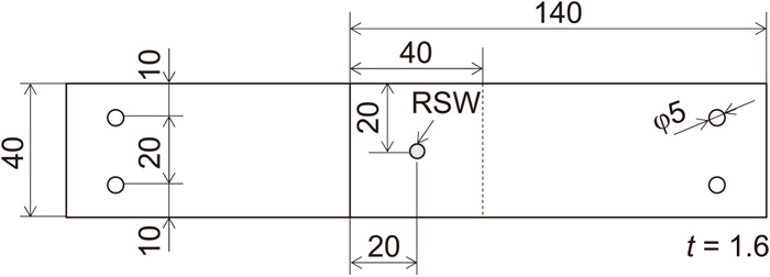
The test materials are 270 and 980 MPa class steel sheets, whose thickness, t, is 1.6 mm. The tensile shear specimens shown in Fig. 1, whose shape was in accordance with JIS Z3138 standard, were fabricated by RSW. The width and length of the plate are 40 and 140 mm, respectively. RSW was performed at the center of 40 × 40 mm overlap area. Tabs with the thickness of 1.6 mm were welded on both ends of the specimens for the axial alignment based on JIS Z3138 standard.
Inverter DC resistance spot welding device and Cr–Cu DR type electrode were used for the welding. The geometries of electrodes are shown in Fig. 2, in which the tip diameters, d, are φ6 and φ12 mm, and tip radiuses of curvature are 40R and 100R. As schematically shown in Fig. 3, by increasing the tip diameter, corona bond length could be increased with keeping the nugget size the same. The tip shown in Fig. 2(a), φ6–40R, is the mostly-standardized geometry, and most widely used in the fabrication processes. However, electrode wearing generally occurs,26,27) which results in the change of tip geometry.28,29,30) It is known that the change of tip geometry due to wearing is more prominent when galvanized steel sheets are welded, because intermetallic compounds are easily formed at the tip of electrodes. In many cases, flattening of the tip of electrodes occurs due to the wearing.28,29,30) The tip shown in Fig. 2(b), φ12–100R, is designed to increase corona bond length with keeping nugget size the same as mentioned above (Fig. 3), and in addition, that geometry is simulating worn tip of electrode. Consequently, the reliability of RSW joints fabricated by worn electrodes can be simultaneously evaluated in the present study, which is important from the viewpoint of welding engineering. The welding conditions are shown in Table 1. When the tip diameters and radiuses of curvature are larger, higher welding pressure is needed to ensure contact of the weld part. In this study, the higher welding pressure conditions are applied for the joints using φ12–100R tip. The welding currents are controlled to obtain the nugget sizes of 3
t
, 4
t
and 4.7
t
. The actual nugget size was proved by the peeling test using the specimens fabricated at several welding conditions. The thickness of weld parts is about 3.1 mm and almost the same in each condition.

Table 1. Wedding conditions.
| 270 MPa-φ6 | 270 MPa-φ12 | 980 MPa-φ6 | 980 MPa-φ12 |
|---|
| Welding pressure | 3.5 kN | 5.0 kN | 3.5 kN | 6.5 kN |
| Weld time | 320 ms |
| Hold time | 20 ms |
Samples for microstructural observation were sequentially polished from No. 80 to No. 4000 emery paper, and mirror finished by buffing. 5% picral (etching time 15 sec) was used for the macroscopic observation of nugget, and 1% nital (etching time of 3 sec) was used for the microstructural observation. The hardness in the nugget was measured by a Micro Vickers hardness tester (MVK TYPE C, Akashi Seisakusho), where the test force of 2.942 N and dwell time of 30 sec.
An electric-hydraulic servo testing machine with the capacity of 20 kN was used for the static tensile shear tests at the crosshead speed of 0.3 mm/min. Fatigue tests were conducted using an electric-hydraulic servo testing machine with the capacity of 50 kN, where the frequency f = 10 Hz and load ratio R = Pmin/Pmax = 0.1 at ambient temperature. The fatigue limit was defined as the maximum load, Pmax, at which fatigue failure did not occur until 107 loading cycles.
3. Results
3.1. Nugget Structure with Corona Bond
Figure 4 shows the typical cross sectional views of the nugget of 980 MPa class steel with the nugget size of 4
t
. Figures 4(a) and 4(b) are the welds made by the electrodes with the tip diameters of 6 and 12 mm, respectively. It should be noted that the corona bond length increased with increasing the tip diameter as schematically shown in Fig. 3. The corona bond lengths of all welds are summarized in Table 2, showing that larger tip diameter resulted in the longer corona bond irrespective of nugget sizes and strength levels of steels. The detailed microstructures of nuggets were described in the previous study,22) where equiaxed ferrite in 270 MPa class steel and full martensite in 980 MPa class steel. It was confirmed from the microstructure observation that the tip diameter did not have any effect on the microstructures in the nuggets.
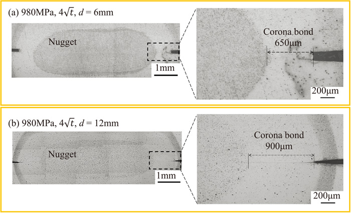
Table 2. Relationship between tip diameter and corona bod length.
| Joint | Tip diameter d (mm) | Corona bond length (mm) |
|---|
| 270 MPa-3
t
| 6 | 1.2 |
| 12 | 1.4 |
| 270 MPa-4
t
| 6 | 0.7 |
| 12 | 1.4 |
| 270 MPa-4.7
t
| 6 | 0.7 |
| 12 | 0.8 |
| 980 MPa-3
t
| 6 | 0.9 |
| 12 | 1.3 |
| 980 MPa-4
t
| 6 | 0.65 |
| 12 | 0.9 |
| 980 MPa-4.7
t
| 6 | 0.6 |
| 12 | 0.8 |
Figure 5 shows typical hardness profiles measured on the cross section of the nugget (4
t
). The profiles were measured along the line 0.4 mm below the mid thickness of the nugget as schematically shown in the figure. The hardness was higher in 980 MPa class steel due to the martensitic structure in the nugget. The larger tip diameter resulted in slightly wider hardened area depending on the welding conditions, while the difference was small. Similar hardness profiles were obtained in the other nugget sizes of 3
t
and 4.7
t
. It seems that the lager tip diameter resulted in the slightly higher hardness near the center of the nugget in 270 MPa class steel. But the dependence of hardness near the center of the nugget on the tip diameter was hardly seen in the other nugget sizes of 3
t
and 4.7
t
. Therefore, the difference of hardness near the center of the nugget of 270 MPa crass steel in Fig. 5 is within a scatter band of hardness. Figure 6 shows the maximum tensile shear loads of joints. Larger nugget sizes resulted in the higher tensile shear loads. The dependence of tensile shear loads on the nugget sizes is larger in 980 MPa class steel, while the tensile shear load seems to be insensitive to the nugget sizes in 270 MPa class steel. It is considered that the plastic deformation around the nugget is much larger in 270 MPa class steel than in 980 MPa class one. The rotation around the nugget generally occurs under tensile shear load depending on the asymmetricity of specimen geometry. The larger plastic deformation around the nugget led to the lager rotation, which resulted in the lower sensitivity of tensile shear load to the nugget sizes in 270 MPa class steel as described in the previous study.22) It should be noted that the effect of tip diameter on the tensile shear loads was not clearly recognized.

Figures 7(a) and 7(b) show the relationships between maximum load in the fatigue tests, Pmax, and number of cycles to failure, Nf, of 270 and 980 MPa class steels, respectively. 270 MPa class steel showed slightly higher fatigue limit at 107 cycles. The results are summarized in Fig. 7(c) for the comparison of all welds. As shown in the figure, when the nugget sizes are 4
t
and 4.7
t
, all results are in a narrow band of P-N relationship, which means that the effects of the nugget size (4
t
or 4.7
t
,) and strength level of steel (270 or 980 MPa) on the fatigue strengths were small. The joints with the nugget size of 3
t
showed lower fatigue strength in the finite life region. 980 MPa class steel showed the lowest fatigue strength, while the fatigue limits at 107 cycles are nearly the same with the other nugget sizes. The fatigue fracture modes were classified into three types as typically shown in Fig. 8, namely interface fracture, plug type fracture and base metal fracture. The failure modes of 270 MPa and 980 MPa steel joints are summarized in Table 3, which shows that the fracture modes are dependent on the load level of fatigue test, nugget size and strength level of steel. Interface fracture tends to occur when the nugget size is small and applied load level is high. In the previous study,22) we have reported that the effect of nugget size on the fatigue strength was very small because fatigue lives of the joints were nearly fully occupied by the crack propagation life from the sheet separation. The larger tip diameter resulted in the longer corona bond as summarized in Table 2, but the effect of tip diameter on the fatigue strength was hardly seen in Fig. 7.

Table 3. Fatigue fracture modes of joints.
| Joint | Tip diameter (mm) | Pmax (kN) |
|---|
| 6.67 | 5.56 | 4.44 | 3.33 | 2.22 |
|---|
| 270-3
t
| 6 | Interface | Interface | Plug | Base metal | Base metal |
| 12 | Interface | Plug | Plug | Base metal | Run out |
| 270-4
t
| 6 | Plug | Plug | Base metal | Plug | Run out |
| 12 | Plug | Plug | Base metal | Base metal | Run out |
| 270-4.7
t
| 6 | Plug | Base metal | Base metal | Base metal | Run out |
| 12 | Plug | Plug | Base metal | Base metal | Run out |
| 980-3
t
| 6 | N/A | Interface | Interface | Interface | Base metal |
| 12 | N/A | Interface | Interface | Interface | Base metal |
| 980-4
t
| 6 | Interface | Plug | Base metal | Base metal | Base metal |
| 12 | Interface | Base metal | Base metal | Base metal | Base metal |
| 980-4.7
t
| 6 | Plug | Base metal | Base metal | Base metal | Base metal |
| 12 | Base metal | Base metal | Base metal | Base metal | Base metal |
4. Discussions
To investigate the effect of corona bond length on the fatigue failure mechanisms, a fatigue test was terminated at 10% of total fatigue life, which is evaluated from Fig. 7 (N/Nf = 10%). Subsequently specimen was cut in the longitudinal direction to observe fatigue cracks around the nugget as schematically shown in Fig. 9. The crack paths were observed only in the joints with the nugget sizes of 3
t
and 4
t
, because the fatigue fracture modes and fatigue lives were nearly the same between 4
t
and 4.7
t
. Figure 10 shows the fatigue crack paths of 270 MPa steel with the nugget sizes of 3
t
. Upper and lower figures correspond to the tip diameters of 6 and 12 mm, respectively. The fracture modes of 3
t
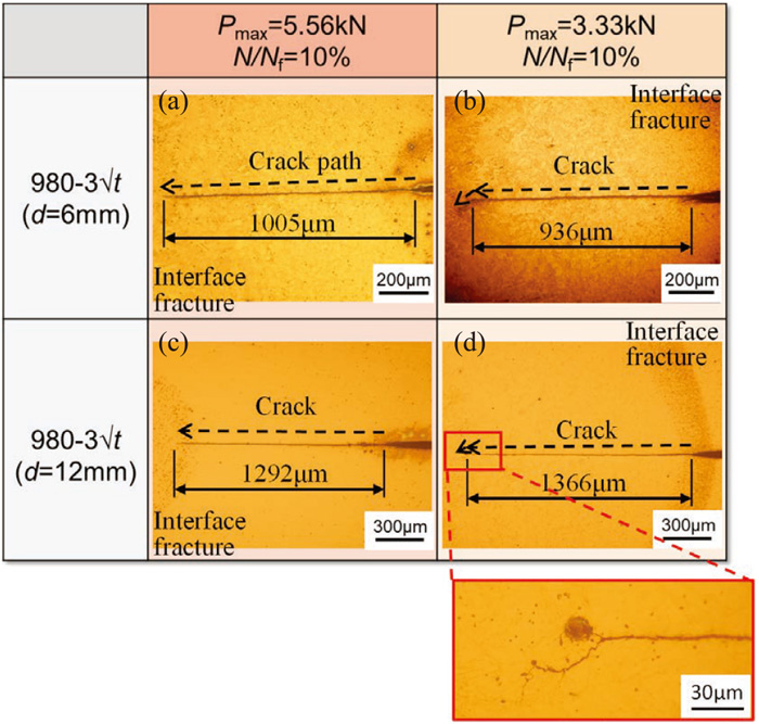
joints shown in Fig. 10 are interface (Fig. 10(a)), plug type (Fig. 10(c)) and base metal (Figs. 10(b) and 10(d)) fractures as summarized in Table 3. Irrespective of the fracture modes and tip diameters, fatigue crack initiated at the sheet separation and propagated some distance along the corona bond. However, it should be noted that the crack lengths along the corona bond were longer when the tip diameter is larger. The crack paths of 980 MPa steel are shown in Fig. 11 (3
t
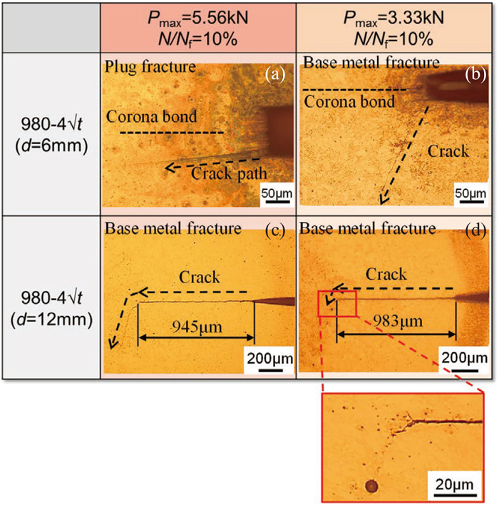
) and Fig. 12 (4
t
). When the nugget size was 3
t
(Fig. 11), interface fracture was dominant and long crack along the corona bond was recognized, where larger tip diameter resulted in the longer crack. In the case of the nugget size of 4
t
(Fig. 12), plug fracture (Fig. 12(a)) and base metal fracture (Figs. 12(b)–12(d)) occurred. When the tip diameter was 6 mm, crack did not grow along the corona bond but propagate into the thickness direction directly from the sheet separation. On the other hand, crack grew along corona bond when tip diameter was 12 mm. From the above observation results, two conclusions can be made. First, relatively long cracks were recognized at 10% of total fatigue life, revealing that the total fatigue life was mainly occupied by the crack propagation life irrespective of tip diameter. Second, increasing tip diameter could successfully induce longer fatigue crack propagation along the corona bond. Additionally, interface fracture was dominant in 980 MPa steel joints with the nugget size of 3
t
(Fig. 11), while fatigue cracks deflected toward thickness direction when the nugget size was 4
t
(Fig. 12). It is considered that when the nugget size is 3
t
, net cross section is too small to induce crack deflection toward thickness direction in 980 MPa steel joints with lower rotation around the nugget than 270 MPa steel ones. The transition nugget size from interface failure to crack deflection toward thickness direction would be between 3
t
–4
t
.


980 MPa steel joints with the nugget size of 3
t
showed the lowest fatigue lives as indicated in Fig. 7. It can be attributed to the lower bonding strength of corona bond, where 0.9–1.3 mm cracks along corona bond were mainly found in the nugget size of 3
t
(Fig. 11). The maximum loads of the fatigue tests of 980 MPa steel are normalized by the nugget circumferential length, and are shown in Fig. 13 by black symbols as a function of Nf, which reveals that the dependence of fatigue strengths on the nugget sizes becomes much smaller irrespective of tip diameter compared with Fig. 7(b). The red symbols in Fig. 13 also show the normalized maximum loads, but in this case, circumferential length was calculated using diameter of nugget size + corona bond length. Ignoring the results of 3
t
samples, the fatigue strengths are nearly the same irrespective of nugget sizes. Only 3
t
samples showed lower fatigue strengths similar to Fig. 7. However, it should be noted that the normalized results of 3
t
samples by nugget size, namely excluding corona bond length (black square symbols), correspond well with the normalized results of 4
t
and 4.7
t
by nugget size + corona bond length (red circular and triangular symbols). It implies that the interface strength of corona bond of 3
t
sample is too weak to contribute to the fatigue strength.

In the present study, lager tip diameter successfully induced crack growth along corona bond as discussed in Figs. 10, 11, 12, while the effect of tip diameter on the fatigue strength was hardly seen in Fig. 7. As summarized in Table 2, corona bond length became 100–700 μm longer when the tip diameter became larger. It is considered that the crack propagation along the longer part of corona bond occurred in very early stage of fatigue life, thus the effect of tip diameter was hardly seen in the total fatigue life. It should be noted that the interface strength of corona bond is the highest near the nugget, and the lowest near the sheet separation depending on the temperature gradient during welding. In the present study, the interface strength distribution along the corona bond was not taken into account. However, the effect of the interface strength distribution on the tensile shear fatigue strength can be neglected because the crack propagation along the longer part of corona bond occurs in very early stage of fatigue life as mentioned above.
Consequently, it can be concluded that when the weld nugget has reasonable size such as 4
t
, the fatigue strengths of welds can be certified from the design fatigue curves shown in Fig. 7, even if the different shapes of electrodes are resulting in the different corona bond lengths. It also means that even if worn electrode with flattened tip is used, fatigue life can be proved when the nugget size is reasonable.
5. Conclusion
Tensile shear fatigue tests were conducted using RSW joints fabricated by electrodes with different tip diameters. The effects of tip diameter, nugget size and strength level of steel were investigated. Cross sectional observation of nuggets revealed that the larger tip diameter resulted in the longer corona bond. The maximum loads in tensile shear tests increased with increasing nugget size and strength level of steel, while insensitive to the tip diameter. In the tensile shear fatigue tests, fatigue strengths were nearly the same when nugget size was larger than 4
t
, while 980 MPa steel joint with the nugget size of 3
t
showed the lowest fatigue strength. Crack growth path observation revealed that the larger electrode tip diameter could successfully induce crack growth along corona bond. However, the effect of tip diameter on the fatigue strength was hardly recognized. The fatigue crack growth along the longer part of corona bond occurred in very early stage of fatigue life, and thus the effect of tip diameter was not apparent. Consequently, a reasonable nugget size, such as 4
t
, is the most important controlling factor for a proper fatigue life, rather than tip diameter and strength level of steel.
References
- 1) N. T. Williams and J. D. Parker: Int. Mater. Rev., 49 (2004), 45. https://doi.org/10.1179/095066004225010523
- 2) N. T. Williams and J. D. Parker: Int. Mater. Rev., 49 (2004), 77. https://doi.org/10.1179/095066004225010541
- 3) M. Pouranvari and S. P. H. Marashi: Sci. Technol. Weld. Join., 18 (2013), 361. https://doi.org/10.1179/1362171813Y.0000000120
- 4) W. Zhang, D. Sun, L. Han, W. Gao and X. Qiu: ISIJ Int., 51 (2011), 1870. https://doi.org/10.2355/isijinternational.51.1870
- 5) I. Ibrahim, R. Ito, T. Kakiuchi, Y. Uematsu, K. Yun and C. Matsuda: Sci. Technol. Weld. Join., 21 (2016), 223. https://doi.org/10.1179/1362171815Y.0000000086
- 6) L. Shi, J. Kang, X. Chen, A. S. Haselhuhn, D. R. Sigler and B. E. Carlson: Fatigue Fract. Eng. Mater. Struct., 43 (2020), 2157. https://doi.org/10.1111/ffe.13256
- 7) K. Yamazaki, K. Satoh and Y. Tokunaga: Q. J. Jpn. Weld. Soc., 17 (1999), 553 (in Japanese). https://doi.org/10.2207/qjjws.17.553
- 8) K. Tohgo, R. Adomi, H. Araki, K. Syoko, H. Tanaka, S. Usuda and Y. Shimamura: J. Soc. Mater. Sci., Jpn., 55 (2006), 1095 (in Japanese). https://doi.org/10.2472/jsms.55.1095
- 9) X. Long and S. K. Khanna: Int. J. Fatigue, 29 (2007), 879. https://doi.org/10.1016/j.ijfatigue.2006.08.003
- 10) H. Gaul, G. Weber and M. Rethmeier: Sci. Technol. Weld. Join., 16 (2011), 440. https://doi.org/10.1179/1362171810Y.0000000031
- 11) T. K. Pal and K. Bhowmick: J. Mater. Eng. Perform., 21 (2012), 280. https://doi.org/10.1007/s11665-011-9850-2
- 12) R. Tanegashima, H. Akebono, M. Kato and A. Sugeta: Int. J. Fatigue, 51 (2013), 121. https://doi.org/10.1016/j.ijfatigue.2012.12.014
- 13) H. Fujimoto, H. Ueda, R. Ueji and H. Fujii: ISIJ Int., 56 (2016), 1276. https://doi.org/10.2355/isijinternational.ISIJINT-2016-043
- 14) T. Fujii, K. Tohgo, Y. Suzuki, T. Yamamoto and Y. Shimamura: Int. J. Fatigue, 87 (2016), 424. https://doi.org/10.1016/j.ijfatigue.2016.02.023
- 15) P. Eftekharimilani, E. M. van der Aa, M. J. M. Hermans and I. M. Richardson: Sci. Technol. Weld. Join., 22 (2017), 545. https://doi.org/10.1080/13621718.2016.1274848
- 16) M. Akita, T. Kakiuchi, M. Nakajima, T. Kawai, Y. Tsubai and Y. Uematsu: Q. J. Jpn. Weld. Soc., 37 (2019), 35 (in Japanese). https://doi.org/10.2207/qjjws.37.35
- 17) S. Ren, N. Ma, S. Tsutsumi, G. Watanabe, H. He, C. Cao and L. Huang: J. Mater. Process. Technol., 299 (2022), 117364. https://doi.org/10.1016/j.jmatprotec.2021.117364
- 18) S. Daneshpour, S. Riekehr, M. Koçak and C. H. J. Gerritsen: Sci. Technol. Weld. Join., 14 (2009), 20. https://doi.org/10.1179/136217108X336298
- 19) R. Tanegashima, H. Akebono and A. Sugeta: Eng. Fract. Mech., 175 (2017), 115. https://doi.org/10.1016/j.engfracmech.2017.01.031
- 20) G. Wu, D. Li, X. Su, Y. Peng, Y. Shi, L. Huang, S. Huang and W. Tang: Int. J. Fatigue, 103 (2017), 73. https://doi.org/10.1016/j.ijfatigue.2017.05.017
- 21) T. Kakiuchi and Y. Uematsu: J. Soc. Mater. Sci., Jpn., 69 (2020), 895 (in Japanese). https://doi.org/10.2472/jsms.69.895
- 22) Y. Uematsu, N. Kawabe, T. Kakiuchi, Y. Kato, Y. Okita, H. Matsuda and T. Tagawa: Q. J. Jpn. Weld. Soc., 37 (2019), 152 (in Japanese). https://doi.org/10.2207/qjjws.37.152
- 23) E. Nakayama: Weld. Int., 21 (2007), 255. https://doi.org/10.1080/09507110701411841
- 24) K. Matsuda and S. Kodama: Sci. Technol. Weld. Join., 25 (2020), 66. https://doi.org/10.1080/13621718.2019.1613010
- 25) K. Matsuda and S. Kodama: Sci. Technol. Weld. Join., 27 (2022), 132. https://doi.org/10.1080/13621718.2021.2023964
- 26) X. Q. Zhang, G. L. Chen and Y. S. Zhang: Mater. Des., 29 (2008), 279. https://doi.org/10.1016/j.matdes.2006.10.025
- 27) M. Kondo, T. Konishi, K. Nomura and H. Kokawa: Sci. Technol. Weld. Join., 15 (2010), 76. https://doi.org/10.1179/136217109X12577814486656
- 28) H. Matsuda, Y. Matsuda and M. Kabasawa: Q. J. Jpn. Weld. Soc., 14 (1996), 47 (in Japanese). https://doi.org/10.2207/qjjws.14.47
- 29) H. Matsuda, Y. Matsuda and M. Kabasawa: Q. J. Jpn. Weld. Soc., 15 (1997), 31 (in Japanese). https://doi.org/10.2207/qjjws.15.31
- 30) M. Kondo, T. Konishi, K. Nomura and H. Kokawa: Q. J. Jpn. Weld. Soc., 27 (2009), 230 (in Japanese). https://doi.org/10.2207/qjjws.27.230


