Abstract
One of the objectives for the development of high-strength dual-phase (DP) steel is improving the stretch-flangeability. Large-strained sheared edges are deformed and frequently cracked during stretch-flange formation. Considering shearing as the first deformation, the stretch-flange deformation may be regarded as a secondary deformation. To improve the stretch-flangeability of the DP steels, many researchers have analyzed the microvoid formation. However, in these analyses, the shearing process was not considered. With this background, ex-situ mini-bending tests combined with scanning electron microscopy (SEM) monitoring of microvoid formation were conducted during the secondary deformation. Prior to the secondary deformation, several microvoids were observed on the sheared surface and fine subgrains formed in the ferrite. During secondary deformation, the preliminary microvoids present at the ferrite-martensite interface propagated into the ferrite phase. In contrast, this behavior was not observed for the reamed surface deformation, which was formed without preliminary deformation. Furthermore, microvoids were initiated on ferrite grains that were not present at the ferrite-martensite interface, and martensite islands were not cracked during secondary deformation. This result is noteworthy because martensite cracking was the main factor involved in microvoid initiation, in the absence of shearing. Electron backscattering diffraction analysis revealed that the work hardening of ferrite, prior to the secondary deformation, caused a deviation in the strain concentration sites from those found in the reamed surface deformation. Therefore, this study elucidated microvoid formation on preliminary deformed surfaces via shearing and provided insights for material development considering deformations on the sheared surfaces of materials.
1. Introduction
Dual-phase (DP) steel is composed of martensite islands and a ferrite matrix. The hard martensite islands strengthen the material without deteriorating its ductility owing to the softness of the matrix. Thus, DP steel exhibits high tensile strength and elongation.1,2) Although steel is commonly used in fabricating automobile parts, its hole expansion ratio (HER) is smaller than that of single-phase steel.1)
The HER is evaluated using a hole expansion test (HET), and it is one of the parameters for quantifying the formability of the steel material. In the HET, a conical punch is used to expand the initial hole pierced on a specimen. When the cracks initiated on the hole surface propagate through the material thickness, the ratio of the initial hole diameter to the expanded hole diameter is calculated as the HER.3) For machined holes, the HER is qualitatively consistent with the material elongation evaluated using tensile tests.4) However, the HER of pierced holes is not related to the material elongation.5,6) Conversely, fracture strain, defined as the local plastic strain at material fracture, is strongly correlated with the HER.7)
Fracture strain is significantly affected by the microvoid nucleation and growth during material deformation.2,8) It is different from material elongation, which is affected by the necking behavior, i.e., the work-hardening ratio in tensile deformation. Owing to the stress and strain localization around the martensite island, the number and size of microvoids observed in DP steel tend to be large.8,9,10,11) Such microvoids induce lower fracture strains when compared with those of single-phase steels.12) To improve the fracture strain, i.e., HER, through the suppression of microstructural strain localization caused by the difference in hardness between ferrite and martensite, researchers have attempted to control the martensite volume fraction,13) tune the martensite morphologies,14,15) and temper the steel to reduce the difference in hardness.13,16,17) These efforts led to a microstructural design for improving the fracture strain. As an extension of these studies, multi-phase steels that include a residual austenite phase have also been investigated to identify the microstructural factors to improve the fracture strain.18,19,20)
As mentioned earlier, material design has been mainly developed based on the microstructural fracture related to the fracture strain evaluated using simple uniaxial tensile tests.21,22) The effect of piercing on the microstructural fracture has rarely been considered, despite the fact that the piercing conditions such as the punch–die clearance,23) punch-edge shape,24) and tool-surface conditions25) significantly affect the HER. The microstructure of DP steel near the sheared surface was observed and its features were discussed,13) but its deformation and damage behavior have not been examined owing to the difficulty in analysis due to the large primary plastic strain on the sheared surface. The plastic strain induced by the piercing is severe, and the value exceeds 4.0.26) The hole-edge deformation in HET is the secondary deformation subsequent to this severe primary deformation in the piercing process. The features of ferrite and martensite around the sheared surface, and the mechanism of nucleation and growth of microvoids during the secondary deformation in the HET remain unclear. Considering that the fracture strain of multi-phase steel exhibits high strain-path dependency,27) microvoid nucleation and growth after the primary and secondary deformations should be different. The elucidation of the different microvoid behaviors will guide material design from the perspective of ductility deterioration due to piercing.
In this context, this study presents the scanning electron microscope (SEM) observation of the sheared surface of laboratory-made 590-MPa-class DP steel, which was deformed by ex situ in-plane bending, to reveal the microstructure and microvoid nucleation and growth behavior. Although the stress and strain states around the fracture parts differed between in-plane bending and HET, the qualitative trends of the fracture limit in the two tests concurred.28) A small specimen that is suitable for SEM can be used in the ex situ test. Therefore, we adopted the in-plane bending test for SEM observation of the sheared surface. Additionally, the observation of the secondary deformation focused on the burnished surface formed by plastic deformation during the piercing process, because the microstructure of the fractured zone is difficult to observe owing to large concavities. The surface formed by machining and reaming (hereinafter called the reamed surface) was also analyzed through ex situ in-plane bending tests. The analysis focused on the hole-edge deformation condition without the primary deformation due to the piercing. We intended to identify the effect of piercing-induced microstructural damage (severe plastic strain and microvoids) on those during the secondary bending deformation. This finding clarified the microstructural features of the sheared surface under severe plastic strain, microvoid nucleation sites in the secondary deformation, and growth behavior of these microvoids.
2. Materials and Methods
2.1. Materials
A laboratory-made DP steel was used in this study. The steel was made to emulate the microstructure of the material with known microvoid behavior in a previous study.8) The chemical composition of the steel is summarized in Table 1. As illustrated in Fig. 1, the ingot was cast by vacuum melting and maintained at 1423 K for 60 min. Then, it was hot-rolled into a 25.0-mm-thick sheet and air cooled to room temperature. Next, the sheet was reheated to 1423 K, maintained at this temperature for 60 min, and hot-rolled to a thickness of 2.9 mm. The sheet was then air-cooled to 923 K and water-quenched.
Table 1. Chemical compositions [mass%].
Martensite islands embedded in the ferrite matrix constituted the DP steel microstructure (Fig. 2), in which the martensite area fraction (≅ volume fraction) was 4.3%. An isotropic distribution of martensite was observed on the surface parallel to the sheet surface (Fig. 2(a)), in contrast to the weak martensite banding observed on the cross section parallel to the rolling direction (Fig. 2(b)).
The mechanical properties are listed in Table 2. The laboratory-made DP steel exhibits mostly the same mechanical properties as the standardized 590-MPa-class DP steel, although its tensile strength was lower by 30 MPa than that of the reference steel.
Table 2. Mechanical properties.
| Initial yield stress [MPa] | Tensile strength [MPa] | Uniform elongation [%] | Total elongation [%] |
|---|
| 335 | 561 | 19 | 31 |
For the ex situ bending tests, the centers of the 50 mm × 50 mm rectangular sheets with a thickness of 2.9 mm were pierced to form a 10-mm-diameter hole. As mentioned in Sec. 1, we focused on the burnished zone of the sheared surface. Therefore, to decrease the fracture zone of the sheared surface, the punch edge was rounded to 0.1 radius, and the clearance between the punch and die was set to a minute value of 10 μm (Fig. 3). Furthermore, the punch was coated with TiCN to obtain a smooth burnished zone without galling and scratching.

The above piercing conditions resulted in the sheared surface shown in Fig. 4. The roundness of the punch edge caused a large rollover with a 10 μm micro-clearance. Moreover, the roundness induced bending of the sheet when the punch had just begun to penetrate the surface. This initial sheet bending caused the burnished surface to bend in the thickness direction (Fig. 4). The burr was also large in the sheared surface. A sheared surface, which was intended to be without a fracture zone, was obtained by means of the roundness of the punch edge, albeit with the abovementioned failures.
2.3. Ex situ Bending Test
The ex situ bending test specimens were formed such that the notch, which was processed by reaming (Fig. 5(a-1)) or piercing (Fig. 5(a-2)), was located at the longitudinal center. The longitudinal direction, i.e., the direction of deformation during bending, corresponded with the transverse direction of the DP steel. The reaming process removed the plastically deformed zone from around the hole edge. Therefore, the reamed surfaces were analyzed as the case that did not involve the primary plastic strain induced by the piercing (PPSP).

Furthermore, the reamed or pierced workpiece was machined to a thickness of 1.2 mm before shaping the ex situ bending specimen. For the pierced workpiece, a 0.2-mm-thick layer was removed from the rollover side, and a 1.5-mm-thick layer was removed from the burr side. The notch curvature for the reamed surface specimen was set to be small so that a larger plastic strain was imposed during the bending than that applied in the case of the sheared notch. The SEM observation of microvoid nucleation requires a larger plastic strain during the bending step of the reamed surface when compared with the case of the sheared surface, because the reamed surface does not involve PPSP. Hence, a smaller notch curvature, which induced strain localization at the bottom of notch, was introduced.
Finally, the specimens were chemically etched by soaking in hydrofluoric acid for revealing the microstructure on the notched surface, as the common methods of polishing cannot be used on a curved surface. Chemical etching removed another 10 μm from the surface, which was below the measurement resolution. Hence, the observed surface exhibited a nearly identical microstructure to the pristine unetched notched surface.
The ex situ bending tests comprised several sequences of bending deformation and SEM observation. In these sequences, bending deformation was induced by a hand-operated mini-bending machine shown in Fig. 5(b). The screw of the machine (on the left in Fig. 5(b)) was turned using a cam mechanism, which raised the V-shaped jig to a position right below the notch. The specimen, which was held by a φ1.0 pin at the top, was subjected to bending deformation.
The observation point was the center of the thickness of the burnished surface, excluding the inclined area at the top of the pierced specimen (Fig. 4). Electron back scattering diffraction (EBSD) revealed the details of the crystal orientations at the notched surfaces before the bending deformation.
3. Results
3.1. Deformation of and Microvoid Formation on the Reamed Surface (The Case without PPSP)
Figure 6(a) illustrates the SEM image and Fig. 6(b) depicts the inverse pole figure (IPF) and image quality (IQ) maps obtained through EBSD. Clear microstructure images were obtained to classify ferrite and martensite despite the additional band-shaped oxides attached to the observed surface; these oxides were not found on the polished and LePera-etched surfaces depicted in Fig. 2. The martensite islands observed in the SEM image (Fig. 6(a)) were recognized as the low-IQ parts in the IQ map (Fig. 6(b)).
Owing to the difficulty in displacement control of the hand-operated bending machine, ex-post elongation evaluation was conducted by using the change in the gauge length in the deformation direction. As shown in Fig. 2(a), the gauge was defined as the distance between two points with characteristic microstructural features.
The following paragraphs discuss the microstructural changes during the ex situ bending test. Figure 7(a) depicts small microvoids formed due to martensite fracture at 6.1% elongation. Three such microvoids are marked in circles with solid boundaries as examples. These groups of martensite fractures occurred under uniform elongation. The uniform elongation of DP steel is 19% (Table 2). Further bending deformation cycles elongated the microvoids, which were caused by martensite fracture along the deformation direction, as demonstrated in the case with 17.9% elongation, which is close to the uniform elongation (Fig. 7(b)). Additionally, strain localization was observed on the ferrite phase surrounding the martensite islands. However, no microvoids nucleated in this stage of deformation. Crack-like steep concavities caused by strain localization on the ferrite phase were initiated at the elongation of 30.3%, i.e., when the uniform elongation was exceeded (parts encircled in dotted and dashed lines in Fig. 7(c)). These crack-like steep concavities penetrated the neck shape of the martensite islands; nevertheless, the neck-shaped part did not fracture. The martensite fracture microvoids further elongated in the deformation direction. The strain-localization zone on the ferrite phase was also enlarged. Bending deformation was applied to the limit of the hand-operated mini-bending test machine (Fig. 7(d)), and the resulting gauge length elongation was 76.7%. Despite such a large deformation, few microvoids nucleated on the ferrite phase. Note that the elongation of 76.7% is closer to the fracture strain of the 590-MPa-class DP steel, reported as approximately 100% in a previous study.29) Hence, the reamed surface in Fig. 7(d) can be regarded as being in the penultimate state before the onset of final fracture. Nevertheless, the microvoid behavior was almost the same as that at smaller elongations. Only the elongation of the martensite fracture void was observed, which was nucleated at an elongation level lower than the uniform elongation, in the deformation direction. The development to the microvoid from the strain-localization zone on the ferrite phase was also observed at the positions circled by the dashed line.

Figure 8 illustrates the SEM image of the microstructure in the burnished zone of the chemically etched sheared surface (Fig. 8(a)) and IPF and IQ maps measured using EBSD (Fig. 8(b)). The SEM image shown in Fig. 8 clearly displays the martensite islands, some of which (e.g., left-most part in the SEM image) formed a banding distribution along the piercing direction, i.e., thickness direction. This tendency was different from the case of the reamed surface without the PPSP, shown in Fig. 6(a). The piercing direction was normal to the specimen surface, whereas the banding direction on the reamed surface was parallel to the sheet surface direction (Fig. 6(a) or Fig. 2(b)).

Another difference between the sheared and reamed surfaces was that several microvoids were formed during the piercing. Hereinafter, we refer to these as microvoids formed on the sheared surface (MFPs). The MFPs occurred as martensite fractures or decohesions near the ferrite/martensite interfaces. Many had crack-like shapes and were directed normal to the piercing direction. A few crack-like microvoids were formed and elongated along the piercing direction.
Notably, the SEM image of the sheared surface does not reveal grain boundaries unlike in the case of the reamed surface, which displayed a polygonal ferrite grain boundary, as shown in Fig. 6(a). These inconspicuous grain boundaries were attributed to grain refinement by the PPSP. Actually, as indicated in Fig. 8(b), the ferrite grains on the sheared surface are remarkably fine when compared with those on the reamed surface. The low IQ values due to the PPSP caused dark patches in the EBSD maps in Fig. 8(b), which complicated the ferrite/martensite classification.
The paragraphs below discuss the microstructural changes during the ex situ bending test, where the gauge length for elongation evaluation is defined in Fig. 8(a).
As indicated by the two points encircled by solid lines in the bending deformation at 2.7% elongation (Fig. 9(a)), microvoids nucleated around the ferrite/martensite interfaces and coalesced with the MFPs; alternatively, the MFP propagated to the ferrite/martensite interface to form new cracks. As shown in the two examples encircled by solid lines, many microvoids nucleated around the ferrite/martensite interfaces and the MFP surface, and the MFPs expanded to form cracks, even at the small elongation of 2.7%. Notably, martensite fractures were not found during the bending deformation, unlike in the case of the reamed surface (Section 3.1). A similar behavior was observed in the case of a larger bending deformation—6.2% elongation in Fig. 9(b). The SEM image depicted the further growth of the microvoids formed at 2.7% elongation. More importantly, several strain-localization regions on the ferrite, i.e., the crack-like steep concavities encircled by dotted lines, were observed at this deformation stage. The elongation of this strain-localization region was directed normal to the bending deformation direction. Thus, the angle between the directions of the strain-localization region and MFP elongation was 90°. The strain-localization region on the ferrite developed into definite cracks at 7.3% elongation (Fig. 9(c)), although the increment in the elongation from the previous bending deformation stage was marginal. Further bending deformation (20.7% elongation in Fig. 9(d)) caused a gaping crack (encircled in dotted line) that extended over half the SEM image. The crack propagated and subsequently coalesced with the other microvoids.

In summary, the PPSP and MFP remarkably altered the microvoid formation in the bending deformation stage. In fact, no microvoids from the ferrite phase were found on the reamed surface, even at 76.7% elongation.
4. Discussion
4.1. Deformation and Microvoid Formation of the Reamed Surface (The Case without PPSP)
The microvoid formation observed on the reamed surface is almost the same as that in the previously reported in situ tensile test of DP steel.
In our previous in situ tensile test on the same grade of DP steel, martensite islands were fractured at an early stage of tensile deformation and these martensite fractures developed to form microvoids.29) We also analyzed the kinematic conditions for such martensite fractures. These early-stage martensite fractures resembled the microvoid formation observed in the ex situ bending test for the reamed surface (Fig. 7(a)). Moreover, Azuma et al.17) conducted an in situ tensile test and SEM analysis; they reported that such microvoids on the martensite phase elongated in the tensile direction and did not propagate into the ferrite phase. These microvoid formations also concurred with the observation in Fig. 7(c).
Generally, it is difficult to observe the microstructure on a necked surface during in situ tensile tests. However, necking in the ex situ bending test did not pose this challenge. Large concavities were not found on the observed surface, whereas necking was observed as the specimen thickness reduced. Therefore, microstructures could be easily observed even at large elongations such as 76.7% (Fig. 7(d)). The observations in the ex situ bending tests revealed that the microvoid nucleation and growth behavior in uniform elongation, observed by Azuma et al.,17) continues at large strains, even after specimen necking.
The reamed surface observations revealed that martensite fractures at the necked parts along the tensile direction were the main mode of microvoid formation, which concurred with previous reports. Therefore, we recommend flattening the necked martensite islands to suppress microvoid formation and increase the fracture strain.
4.2. Deformation and Microvoid Formation of the Sheared Surface (The Case with PPSP)
The tensile specimens cannot be extracted from the sheared surface in an actual machining process. However, the ex situ bending tests successfully substituted the in situ tensile tests, as mentioned in Sec. 4.1. The microvoid formation behaviors during the bending tests were identical to that observed in the in situ tensile tests. Thus, the microvoid observation in the ex situ bending test has reference value for the in situ tensile tests of DP steels. This is the first study to clarify the effect of PPSP and MFP on microvoid formation during the eventual deformation of DP steel due to piercing by referring to the results of the conventional in situ tensile tests.
The microvoids formed on the sheared surface during the bending deformation were markedly different from those in the reamed surface or in situ tensile tests. The most notable difference was the existence of MFPs on the sheared surface. The microvoid expansion in the bending deformation was mainly attributed to MFP growth.
MFPs were observed around the ferrite/martensite interface, and martensite fractures were seldom found on the sheared surface before the bending deformation. In contrast, the deformation of the reamed surface seldom exhibited ferrite/martensite interfacial fractures, as shown in Fig. 7. Such microvoid formations initially observed on the sheared surface are similar to the observations of the inner part around the fractur surface of the tensile specimen.8,11) This similarity must have been caused by the chemical etching of the surface shown in Fig. 8(a), which exposed the interior fractures at the ferrite/martensite interface formed by piercing.
The absolute value of plastic strain on the sheared surface was uncertain. However, a previous report on piercing simulation26) suggested that a plastic strain exceeding 4.0 should be imposed. The change in the martensite morphology before (Fig. 2(a)) and after (Fig. 8(a)) piercing supported this suggestion. Considering that the original sheet surface, which formed the hole surface, was pushed into the hole edge, we concluded that the microstructure of the sheared surface was originally located on the sheet surface. Therefore, the rolling direction in Fig. 2(a) corresponds to the thickness (piercing) direction in Fig. 8(a). By comparing the SEM images in the two figures, it can be seen that the isotropic distribution of martensite islands in Fig. 2(a) changed to banding distribution along the piercing direction in Fig. 8(a). The severe plastic shear deformation, reported in the literature,26) caused this change in morphology.
The large plastic strain caused ferrite grain refinement and deterioration of the ductility of the sheared surface. As is commonly known, severe plastic shear deformation induces dense dislocations, which develop into cells that form new ferrite grain boundaries. Nakada et al.30) also observed the same type of ferrite around a sheared surface. They predicted the formation and propagation of ductile cracks in high-strain and fine-grained ferrites during hole expansion due to the low ductility of ferrite. The ex situ bending test in this study substantiated their prediction. Unlike in the case of the reamed surface (Fig. 7), ferrite fracture was primarily formed as microvoids during bending deformation of the sheared surface, whereas martensite fractures were rarely observed (Fig. 9). As shown in Fig. 7, ferrite fractures were seldom observed in the reamed surface deformation, whereas martensite fractures were conspicuous.
Furthermore, the strain localization sites that appeared during the bending deformation (Fig. 9) were different from those that appeared during piercing deformation. In the case without PPSP, the plastic strain was localized on the ferrite phase between plural martensite islands in DP steel.15) Especially, the plastic strain localized on the ferrite sandwiched by the martensite islands along the deformation direction was remarkably large, and microvoids formed on the highly strained ferrite, as observed inside the tensile fractured specimen.9,11) Likewise, numerous microvoids were found on the ferrite phase near the ferrite/martensite interface after piercing, where this region was sandwiched by two martensite islands along the piercing direction (Fig. 8(a)). However, these sites were altered during bending deformation so that the martensite sandwiching direction was along the bending deformation (Figs. 9(b) and 9(c)). Some microvoids were formed outside the ferrite/martensite interface; these are encircled in dotted lines in the figure. Such microvoid formations have never been observed in tensile deformation of DP steels without PPSP. Therefore, this microvoid formation is regarded as peculiar to DP steels with PPSP.
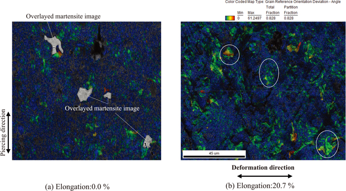
Despite the aforementioned difference in the strain-localization sites in the piercing and bending deformation processes, the strain-localization sites that appeared during piercing continued to deform during the bending deformation. The maps of the grain reference orientation deviation (GROD), which was calculated as the deviation from the average grain orientation and provided the qualitative distribution of the plastic strain,31) support this fact. Figure 10 illustrates the GROD maps before and after the bending deformation. As indicated, three martensite islands were overlayed on the sheared surface before the bending deformation (Fig. 10(a)). Figure 10(a) illustrates the dense GROD around the ferrite/martensite interfaces; the dense-GROD sections and martensite islands are aligned in the piercing (PPSP) direction. These tendencies prove the plastic strain localization behavior mentioned earlier. Although the overall GROD of the sheared surface increased after the bending deformation, its most remarkable increase occurred around the pre-existing high-GROD regions (Fig. 10(b)), encircled in solid lines in the figure. Of course, the concavities developed due to surface deformation increase the GROD. However, this expansion of the high-GROD region was so remarkable that the increase in GROD exceeded the effect of surface concavities. Hence, we can consider that the sites of strain localization due to piercing were the same as those in bending deformation despite the change in the deformation direction. This led to the inference that ferrites that were severely work-hardened by the strain localization in piercing deformation served as the hard phase, and additional strain localization was induced around them.
It can be concluded that the microvoids observed during the bending deformation (Fig. 9) were formed as the synergetic effect of three deformation factors—martensite islands, MFP, and significantly work-hardened ferrite region.
Hence, to improve the ductility of a sheared surface during the subsequent deformation, we recommend controlling the material properties for the piercing process by considering the behavior of plastic strain localization, MFPs, and the ferrite work-hardening in a large strain. The effects of additional factors, e.g., unevenness and pre-existent cracking on a fracture zone of a sheared surface, should be considered in an actual HET, because cracking is generally initiated on a fracture zone. The elucidation of these effects for an actual HET will facilitate the novel material design of high-HER DP steels for resistance against damage on the sheared surface.
Such analyses require evaluating the initial microstructural damage distribution on a sheared surface. Piercing induces a complex heterogeneous damage distribution, complicating the analysis of the sheared surface. The conventional method cannot numerically simulate such a complicated damage distribution. Therefore, instead of attempting to overcome this difficulty in numerical simulation, the initial microstructural heterogeneity can be utilized for easy morphological characterization before and after the piercing deformation. Heuristic models such as those based on deep learning can possibly predict the damage distribution according to the microstructural characters, e.g., martensite morphologies. We will adopt this approach in a future study.
5. Summary
The formation of microvoids during the bending deformation subsequent to piercing was investigated in this study. We used 590-MPa-class DP steel with 4.7 vol% martensite (the actual tensile strength was 560 MPa) for the investigation. For comparison, the microvoid formation on a reamed surface was also investigated as the case without piercing-induced plastic strain. Based on the results, the effect of piercing on microvoid formation during bending was elucidated. The aim of these investigations was to provide guidance for material design to realize high-HER DP steels.
To this end, an ex situ bending test was conducted using a hand-operated mini-bending machine. Miniature bending specimens were cut from pierced and reamed hole edges for the ex situ bending test. The ex situ test involved bending and SEM observation of the specimens.
The findings are as follows:
(1) Martensite fractures occur during the bending deformation of a reamed surface at an early stage of deformation under uniform elongation, where the martensite fractures develop to microvoids. The large deformation causes the surface to elongate by 76.7%. However, microvoids induced by the martensite fractures elongate only along the deformation direction and do not propagate into the ferrite phase. This behavior is almost the same as that reported in the previous in situ tensile tests.
(2) The sheared surface presents a remarkably different microvoid formation than the reamed surface. Microvoids appear on the ferrite phase or the pre-existing microvoids formed by piercing extend to the ferrite phase during the bending deformation. The low ductility of the fine-grained ferrite phase due to the piercing-induced strain causes the microvoid formation.
(3) The observation of the microvoids clarified the difference in the strain-localization site between the piercing and bending deformations. The microvoid formation sites are different for the two types of deformations. However, GROD analysis suggested that the strain-localization site during piercing deformation induces additional strain localization. This is because the significantly work-hardened ferrite phase caused by piercing deformation serves as the hard phase during bending deformation.
Acknowledgement
This study was supported by JSPS KAKENHI (Grant Number JP17K14844).
References
- 1) M. Takahashi: Nippon Steel Tech. Rep., (2003), No. 88, 2. https://www.nipponsteel.com/en/tech/report/nsc/pdf/n8802.pdf, (accessed 2023-03-22).
- 2) Y. L. Su and J. Gurland: Mater. Sci. Eng., 95 (1987), 151. https://doi.org/10.1016/0025-5416(87)90507-6
- 3) ISO 16630: 2017, Metallic materials - Sheet and strip - Hole expanding test.
- 4) S. Nomura and T. Kuwabara: ISIJ Int., 62 (2022), 191. https://doi.org/10.2355/isijinternational.ISIJINT-2021-365
- 5) A. Konieczny and T. Henderson: SAE Trans., 116 (2007), 20. https://doi.org/10.4271/2007-01-0340
- 6) J. Lee, S. Lee and B. C. De Cooman: Mater. Sci. Eng. A, 536 (2012), 231. https://doi.org/10.1016/j.msea.2012.01.003
- 7) T. Matsuno: Sokeizai, 53 (2012), 2 (in Japanese).
- 8) T. Matsuno, D. Maeda, H. Shutoh, A. Uenishi and M. Suehiro: ISIJ Int., 54 (2014), 938. https://doi.org/10.2355/isijinternational.54.938
- 9) G. Avramovic-Cingara, Y. Ososkov, M. K. Jain and D. S. Wilkinson: Mater. Sci. Eng. A, 516 (2009), 7. https://doi.org/10.1016/j.msea.2009.03.055
- 10) M. Kikuzuki, K. Hayashi, Y. Tsunemi, S. Yabu and T. Matsuno: Tetsu-to-Hagané, 106 (2020), 244 (in Janpanese). https://doi.org/10.2355/tetsutohagane.TETSU-2019-111
- 11) J. Kadkhodapour, A. Butz and S. Ziaei Rad: Acta Mater., 59 (2011), 2575. https://doi.org/10.1016/j.actamat.2010.12.039
- 12) Y. Nakagawa, T. Matsuno, T. Hama, T. Naito, Y. Okitsu, S. Hayashi and K. Takada: Proc. 71st Jpn. Joint Conf. for the Technology Plasticity, JSTP, Tokyo, (2020), 355 (in Japanese).
- 13) K. Takashima, K. Hasegawa, Y. Toji and Y. Funakawa: ISIJ Int., 57 (2017), 1289. https://doi.org/10.2355/isijinternational.ISIJINT-2017-086
- 14) S. Sun and M. Pugh: Mater. Sci. Eng. A, 335 (2002), 298. https://doi.org/10.1016/S0921-5093(01)01942-6
- 15) T. Matsuno, T. Yoshioka, I. Watanabe and L. Alves: Int. J. Mech. Sci., 163 (2019), 105133. https://doi.org/10.1016/j.ijmecsci.2019.105133
- 16) X. Fang, Z. Fan, B. Ralph, P. Evans and R. Underhill: J. Mater. Process. Technol., 132 (2003), 215. https://doi.org/10.1023/A:1025913123832
- 17) M. Azuma, S. Goutianos, N. Hansen, G. Winther and X. Huang: Mater. Sci. Technol., 28 (2012), 1092. https://doi.org/10.1179/1743284712Y.0000000006
- 18) Y. R. Im, E. Y. Kim, T. Song, J. S. Lee and D. W. Suh: ISIJ Int., 61 (2021), 572. https://doi.org/10.2355/isijinternational.ISIJINT-2020-388
- 19) A. Nagasaka, T. Hojo, M. Fujita, T. Ohashi, M. Miyasaka, Y. Shibayama and E. Akiyama: ISIJ Int., 61 (2021), 1980. https://doi.org/10.2355/isijinternational.ISIJINT-2020_719
- 20) A. Nagasaka, T. Hojo, Y. Shibayama, M. Fujita, T. Ohashi, M. Miyasaka and E. Akiyama: ISIJ Int., 62 (2022), 247. https://doi.org/10.2355/isijinternational.ISIJINT-2021-092
- 21) Y. Mugita, M. Aramaki, M. Yamamoto, A. Takeuchi, M. Takeuchi, T. Yokota, Y. Funakawa and O. Furukimi: ISIJ Int., 59 (2019), 1362. https://doi.org/10.2355/isijinternational.ISIJINT-2018-762
- 22) H. Kawata and O. Umezawa: ISIJ Int., 61 (2021), 1002. https://doi.org/10.2355/isijinternational.ISIJINT-2020-595
- 23) T. Matsuno, J. Nitta, K. Sato, M. Mizumura and M. Suehiro: J. Mater. Process. Technol., 223 (2015), 98. https://doi.org/10.1016/j.jmatprotec.2015.03.041
- 24) T. Matsuno, Y. Kuriyama, H. Murakami, S. Yonezawa and H. Kanamaru: Steel Res. Int., 81 (2010), 853.
- 25) T. Matsuno, K. Sato, A. Uenishi, S. Higuchi, T. Masuda and T. Shimizu: J. Jpn. Soc. Technol. Plast., 56 (2015), 133 (in Japanese). https://doi.org/10.9773/sosei.56.133
- 26) T. Matsuno, Y. Sekito and K. Kawasaki: J. Mater. Process. Technol., 229 (2016), 570. https://doi.org/10.1016/j.jmatprotec.2015.10.012
- 27) T. Matsuno, T. Matsuda, H. Shoji and M. Ohata: Metals, 12 (2022), 776. https://doi.org/10.3390/met12050776
- 28) T. Matsuno, K. Sato, R. Okamoto, M. Mizumura and M. Suehiro: J. Mater. Process. Technol., 230 (2016), 167. https://doi.org/10.1016/j.jmatprotec.2015.10.018
- 29) T. Matsuno, T. Hojo, I. Watanabe, A. Shiro, T. Shobu and K. Kajiwara: Sci. Technol. Adv. Mater.: Methods, 1 (2021), 56. https://doi.org/10.1080/27660400.2021.1922207
- 30) N. Nakada, K. Ikeda, H. Shuto, T. Yokoi, T. Tsuchiyama, S. Hata, H. Nakashima and S. Takaki: Tetsu-to-Hagané, 102 (2016), 253 (in Janpanese). https://doi.org/10.2355/tetsutohagane.TETSU-2015-086
- 31) M. N. Gussev and K. J. Leonard: J. Nucl. Mater., 517 (2019), 45. https://doi.org/10.1016/j.jnucmat.2019.01.034


