1. Introduction
Manganese has a wide range of applications, involving various aspects of human production and life.1,2) For example, it is used to produce alloys in steel production,3,4,5) MnO2 and KMnO4 are commonly used as deoxidizers in wet metallurgy,6,7) and Manganese used as a raw material for ternary batteries.8,9,10) With the depletion of manganese lump ore regarded as a high-quality manganese ore resource, manganese ore fines gradually play an important role in obtaining manganese resources.11,12)
Sintering is considered to be the most effective method for producing qualified electric furnace burden with excellent chemical and physical properties, as well as an important way to transform manganese ore fines into agglomerate.13) Therefore, the effect of sintering conditions on the traditional manganese ore sintering behavior has been studied by many scholars. Ahmed A14) discovered that increasing the amount of manganese sintered ore in electric furnaces is beneficial in reducing energy consumption and the generation of fines. Ding Y.H.15) found that manganese ore fines sintering requires a high moisture and high coke level. Better sintering indices could be obtained under the condition of a fuel ratio of 10% and moisture content of 18%, while the solid fuel consumption was relatively high at 208 kg/t. Zhao Q.16) also conducted similar sintering pot test using manganese ore fines and found that when the coke level was 10.0%, the obtained sinter yield was 79.7%, with a utilization coefficient of 0.64 t·m−2·h−1, and solid fuel consumption of 193.9 kg/t. Zhang Y.B.17) also recommended the optimal coke breeze dosage to be 9.9% for sintering high-Fe Manganese Ore fines. As evident from the comprehensive literature, the current sintering process of manganese ore fines generally suffers from high fuel consumption and low productivity issues, which clearly contradicts the principles of low-carbon and green development.
The pellet-sintering method aims at realizing true combination of sintering process and pelletizing process to improve sintering performances.18,19) The pellet sintering process adopted a fuel segregation technique, where some coke fines (<1 mm), return fines (<1 mm), finely ground flux, and finely ground iron ore were prepared into pellets of 8–16 mm.20,21,22) The remaining coke and return fines were then coated on the outer surface of the pellets. Subsequently, the pellets were dried, ignited, and sintered after insulation.20) Compared with Hybrid pelletized sintering (HPS), the coarse iron ore fines and fluxes are needed to be pretreated by crushing and ball milling process, which beneficial for pelletizing process in pellet sintering process (PS).23,24) Therefore, the green balls with the size of 5–10 mm have higher mechanical strength in PS than HPS. In addition, the coarse return fines with size of 1–5 mm would not participate in pelletizing process, but mix with the green balls in PS. Hence, this part of return fines and coarse coke would fill in the gaps of the pellets. In the sintering process, the return fines can promote the liquid phase generation, which can make the pellets to bond together effectively leading to the higher mechanical strength of product sinter. Therefore, compared with HPS, PS aims at realizing true combination of sintering process and pelletizing process to improve sintering performances. Pellet sintering can significantly reduce solid fuel consumption during the sintering process and improve the quality of the sinter. Currently, this agglomeration method has been successfully applied to chromite ore and laterite nickel ore. When the pellet-sintering method is applied to process laterite nickel ores, the sinter tumble strength and productivity increase from 45.87% and 0.97 t·m−2·h−1 to 1.17 t·m−2·h−1 and 54.27%, respectively. while the solid fuel consumption during the sintering process is reduced by 47.72 kg/t.19) Zhu D.Q.20) found that the sinter tumble index increased by 54.02% compared to conventional sintering, and the solid fuel consumption decreased by 29.29%, when chrome iron concentrate processed by pellet sintering. In conclusion, the pellet-sintering method can effectively improve the sinter performance and reduce solid fuel consumption during the sintering process. In this paper, the effect of coke breeze dosage and pellet size on sintering performance was studied, as well as the consolidation mechanism of sinter products processed by pellet sintering.
2. Materials and Methods
2.1. Materials
The manganese raw materials consist of four types of manganese ore fines and a dust ash, and their chemical compositions are shown in Table 1. Bentonite is used as a binder for pellets, with a dosage of 1.0%. The sintering mixture is designed with a manganese content of 34.0%, a Mn/Fe ratio of 3.2, and an Al2O3 content of 5.0%.
Table 1. Chemical composition of raw materials (wt, %).
| Compositions | TMn | MnO | TFe | CaO | SiO2 | Al2O3 | MgO | LOI |
|---|
| SA-I | 33.65 | 43.44 | 13.42 | 4.23 | 15.18 | 1.32 | 0.81 | 7.65 |
| OA-I | 23.33 | 30.12 | 9.37 | 0.81 | 32.44 | 6.48 | 0.43 | 11.30 |
| SA-II | 34.73 | 44.83 | 5.76 | 13.63 | 7.06 | 0.84 | 2.96 | 19.86 |
| ML-I | 38.83 | 50.13 | 5.32 | 0.95 | 14.50 | 4.74 | 0.36 | 11.82 |
| Coke | – | 0.25 | 9.01 | 4.56 | 46.68 | 27.92 | 1.14 | 84.32 |
| Bentonite | – | 0.03 | 5.77 | 6.17 | 49.68 | 17.03 | 2.22 | 11.45 |
| Dust-ash | 20.93 | 27.02 | 0.72 | 1.88 | 26.42 | 2.38 | 4.06 | 4.18 |
The X-ray diffraction patterns of the four types of manganese ore fines and dust ash are shown in Fig. 1. It can be observed that the manganese minerals in SA-I, SA-II, OA-I and ML-I are primarily composed of manganese dioxide (MnO2), and the manganese phases in the dust ash are predominantly composed of manganese tetraoxide (Mn3O4).

Fig. 1. XRD pattern of raw material (1-Mn2O3, 2-MnCO3, 3-FeMnO3, 4-CaMn(CO3)2, 5-CaMn6SiO12, 6-(Mn2O3)MnSiO3, 7-Fe2O3, 8-CaCO3, 9-SiO2, a-KMn8O16, b-MnO2, c-K6Fe2O5, d-Mn3O4, e-K2Mn2(SiO4)3, f-KCl). (Online version in color.)
The pellet-sintering process for manganese ore fines includes additional steps of raw material pretreatment (manganese ore fines was finely ground to −0.074 mm accounting for 60%) and pelletizing, and the flow chart is as follows as shown in Fig. 2. The green balls were prepared on a pelletizing disc with a diameter of Ф=1000 mm, a rotation speed of 28 r/min, a side height of h=150 mm, and an inclination angle α=47°. By adjusting the pelletizing parameters, green pellets with wet crush strength greater than 10 N/piece and a drop number greater than 3 times/0.5 m were produced, with a particle size of 8–16 mm.

Fig. 2. The flow diagrams of the pellet-sintering process.
After pelletizing, the green balls were loaded into the sinter pot. Prior to that, 1 kg of base bedding material (10–16 mm) was added into a Φ150 mm×700 mm sinter pot. The bed height was set at 720 mm and gently pressed to 600 mm after being loaded. The ignition temperature was set at 1100±50°C for a duration of 90 seconds, with an ignition vacuum of 5 kPa. After that, the sintering vacuum was adjusted to 9 kPa. The evaluation of the sintered product mainly considers the sintering productivity (P, %), solid fuel consumption (SFC, kg/t), sinter tumble index (TI, %), and yield (Y, %). During the sintering process, the temperature of the bed at 250 mm and 500 mm from the top was measured using thermocouples, and the sintering flue gas was analyzed using an Infrared Gas Analyzer (Madur-Photon, Austria). A total of 5 kg of various finished ore particles, according to the weight ratio, was crushed to 3–5 mm. This portion of the sample will be used for mineralogical analysis or microscopic observation.
2.2.2. XRD Analysis
Taking a total of 5 kg of various finished ore particles according to the weight ratio and crush them to below 1 mm. After that, mix them thoroughly and reduce them to 500 g using sample divider. Then, finely grind the sample to below 0.074 mm and mix it uniformly. Take 10 g of the sample for XRD analysis using RIGAKU D/Max 2500 from Japan.
2.2.3. Microstructure and Composition
The microstructure and micro-composition of sinter was studied by using Scanning electron microscopy (SEM, Nova NanoSEM 450, America) and energy spectrometer (EDS, AZtec X-MaxN80, England). The samples were then subjected to a polarizing microscope (Zeiss Axioskop 40A pol, Germany) for mineral phase study.
3. Result and Discussion
3.1. Sintering Indices
3.1.1. Effect of Coke Breeze Dosage on Sintering Indices
The effect of coke breeze dosage on pellet-sintering performance is shown in Fig. 3. When the coke dosage increases from 3.3% to 3.9%, the yield and tumble index increase from 70.42%, 51.7% to 76.54%, 62.5%, respectively. Meanwhile, the productivity initially increases and then decreases, reaching its maximum value of 1.31 t·h−1·m−2 when the coke dosage is around 3.7%. This phenomenon is caused by the excessive coke breeze dosage, leads to a thicker combustion zone and a decrease in flame front speed. In addition, the solid fuel consumption also increases from 53.04 kg/t to 60.7 kg/t with an increase of coke breeze dosage. Taking into account the impact of solid fuel consumption, the recommended optimal coke dosage for sintering manganese ore fines is 3.5%. At this dosage, the sintering yield, tumble index, productivity, and solid fuel consumption are 72.61%, 60.7%, 1.27 t·h−1·m−2, and 54.7 kg/t, respectively. It is apparent that the coke breeze dosage for sintering is significantly lower compared to conventional sintering processes, where the coke breeze dosage is usually between 5% to 10%.21,22,23,24,25) This directly achieves energy savings and carbon emissions reduces in the sintering process of manganese ore fines.

Fig. 3. Influence of coke breeze dosage on the results of pellet-sintering (a- effect of coke breeze dosage on yield and tumble index, b- effect of coke breeze dosage on solid fuel consumption and utilization coefficient). (Online version in color.)
Compared to conventional sintering, finely ground manganese ore fines were used as raw material during pellet sintering. The increased specific surface area of the ore fines leads to an increase in the reaction sites between particles, which benefits the internal solid-phase reactions in the pellets and promotes the interconnectivity and crystallization of the grains.26,27) On the other hand, the material surface was soaked with hot air after ignition, which is not only conducive to ensure the highest temperature of flame front and its flame front speed but also promotes crystallization in the sintering zone.28,29) Compared with traditional sintering of different types of manganese ore fines, pellet-sintering significantly owns lower solid fuel consumption and lower carbon emissions.30,31) Additionally, pellet-sintering has a lower return fine rate, indicating that the pellet-sintering process can achieve higher product yield, as shown in Table 2. From the perspective of solid fuel consumption, pelletizing is clearly superior to traditional sintering of manganese powder ores.
Table 2. Energy efficiency analysis of manganese ore pellet sintering.
| Project | units | Manganese carbonate sintering | Manganese oxide ore Sintering | Pellet sintering |
|---|
| Energy Consumption of Raw Material Pretreatment | kW·h/t | – | – | 45.75 |
| Sintering Energy Consumption | kgce/t | 84.69–140.67 | 129.18–172.25 | 58.4 |
| Total Energy Consumption | kgce/t | 84.69–140.67 | 129.18–172.25 | 78.16 |
| CO2 Emissions | kgCO2/t | 211.13–350.69 | 322.05–429.42 | 194.85 |
| Interval of softening | °C | 100 | 120 | 101 |
| Return fine rate | % | 30–40 | 35–40 | 25 |
Note: 1 kW·h=3.6*106J, 1 kgce≈7000 kcal, 1 kgce≈2.49 kgCO2.
The effect of pellet size composition on the sintering performance is shown in Fig. 4. An appropriate increasing in pellet particle size can improve the productivity and reduce solid fuel consumption. However, an excessively large particle size composition can deteriorate the tumble index of the sinter products and yield. As shown in Figs. 4(a) and 4(b), when the main particle size of the pellet changes from 8–10 mm to 10–12 mm, the productivity increased from 1.24 t·h−1·m−2 to 1.29 t·h−1·m−2. The yield, tumble index, and solid fuel consumption decreased from 72.09%, 63.03%, and 56.75 kg/t to 71.12%, 62.48%, and 55.87 kg/t, respectively. When the particle size further increases to 12–16 mm, the productivity, yield, and tumble index further decrease to 1.11 t·h−1·m−2, 64.09%, and 57.47%, respectively, while solid fuel consumption increases to 61.47 kg/t. This is because the larger pellet particle size lead to the higher permeability of the burden layer becomes, resulting the maximum temperature of the flame front reduced and the crystallization time of the finished ore zone shortened.32) Ultimately, this leads to a decrease in the quality of the sinter product. In addition, there is a “edge effect” during the sintering, where the temperature at the edge of the sintering bed is lower than the temperature at the center of the burden layer. If the pellet particle size is too large, the phenomenon of “under sintering” of pellets at the edge of the sintering bed will be more prominent, leading to a decrease in the yield of the sinter product.33) This phenomenon can be observed from Fig. 4(d), where the outer surface of the sinter cake is mostly spherical, while the inside is mostly in the liquid phase. Based on that, it is recommended that the optimal particle size for pellet-sintering is 8–12 mm.

Fig. 4. Effect of pellet particle size composition on sintering results (a- pellet particle size composition, b- effect of pellet particle size composition on sintering indices, c- macroscopic view of pellets and burden, d- sintered pellet product). (Online version in color.)
The effect of mean size of sinter mixture on sintering flue gas flow rate was shown in Fig. 5(a) under the condition of 5.0% coke level in traditional sintering and 3.5% coke level in pellet sintering. The sintering flue gas flow rate increases significantly with an increase of mean size of sinter mixture. Interestingly, the time of gas flow rate increases has gradually advanced. This is because the increase in particle size of the sintering mixture leads to a significant improvement in the permeability of the sintering layer, resulting in an increased gas flow rate. At the same time, the improved sintering permeability also contributes to the acceleration of the sintering process, leading to a gradual advancement of the time of gas flow rate increases.

Fig. 5. The variation of sintering gas flow rate over time (a- Gas flow rate of sintering; b- Changes of O2, CO, and CO2 contents in the outlet flue gas of manganese ore fines pellet sintering). (Online version in color.)
The optimal coke breeze dosage for manganese ore fines pellet sintering was found to be 3.5 wt.% with the pellet main particle size of 10–12 mm, while the appropriate coke breeze dosage for iron ore sintering was only in the range of 3.3 wt.%–5.0 wt.%.34,35) However, pellet sintering involves the insulation process through natural gas combustion. Thus, the sintering atmosphere for pellet sintering must be different from that for the iron ores sintering. The CO content of gas in the latter may be lower than in the former. As shown in Fig. 5(b), after ignition, the O2, CO, and CO2 contents in the outlet flue gas of pellet sintering were in the range of 12.0 vol.%–13.0 vol.%, 2.8 vol.%–4.5 vol.% and 6.0 vol.%–10.0 vol.%, respectively. As reported, however, the CO2 content in the flue gas of high-Fe Mn-ore sintering was 7.5 vol.%–8.0 vol.% and the CO content in the flue gas of iron ore sintering was only 1.0 vol.%–2.2 vol.%.17,36) This may also imply that the reducing atmosphere during the sintering process of manganese ore pellets is weaker than that of traditional sintering for its lower coke level and better permeability.
3.2. Discussion on the Phase Formation
3.2.1. Chemical Composition
The product sinter after the free-fall test is sieved using ISO standard sieves (5 mm, 10 mm, 16 mm, 25 mm, and 40 mm) for particle size classification. A mass of 10 kg is taken for each size fraction. The samples will be uniformly crushed to below 1 mm and then further reduced to 1 kg. Then, this 1 kg sample is ground into powder for measuring the chemical composition of the product sinter. the chemical composition of the product sinter with a primary particle size of 8–10 mm and a coke level of 3.5% was display in Table 3. It can be seen that the FeO, Mn (II), and SiO2 contents are 10.52%, 17.41%, and 22.78% respectively.
Table 3. Analysis of chemical composition of sinter (wt, %).
| chemical composition | TMn | Mn2+ | TFe | FeO | CaO |
|---|
| Sinter product | 33.65 | 17.41 | 10.52 | 0.31 | 5.44 |
Continue the above table 4
| chemical composition | SiO2 | Al2O3 | MgO | K2O | Na2O | P | S |
|---|
| Sinter product | 22.78 | 4.95 | 1.60 | 1.64 | 0.36 | 0.15 | 0.15 |
XRD analysis was carried out to investigate the main phases of the sinters with natural basicity. It can be observed From Fig. 6 that there are five mineral phases in the product sinter, namely, hausmannite (Mn3O4), ferrotephroite ((Fe,Mn)2SiO4), Fe–Mn oxides (FexMn3-xO4), bustamite ((Mn,Fe,Ca)·5(Si5O15)), quartz (SiO2). Based on the diffraction peak intensities of different phases, it can be roughly determined that the main phases in the product sinter are hausmannite and ferrotephroite, followed by Fe–Mn oxides.

Fig. 6. The XRD pattern of the sinter.
The macroscopic images of the surface and deep layers of the sinter plug are observed as shown in Figs. 7(a) and 7(b). The surface and partial edges of the sinter cup are mostly spherical in shape, with the sinter being surrounded by a liquid phase. The deep layer of the sinter plug is similar to ordinary product sinter, with a porous and loose structure and a well-developed liquid phase. The solidification methods and respective phase compositions of the product sinter at different locations can be observed from Figs. 7(a1) and 7(b1). As shown in Fig. 7(a2), the main phases in the spherical product sinter are skeletal ferrotephroite and blocky hausmannite, and the hausmannite grains are small (generally 5–15 μm) and evenly distributed. Moreover, there are some bridging bonds between the hausmannite, which leads to a tight connection between the grains and conductive to enhance the strength of the product sinter. The mineral phase diagram of the bottom product sinter is shown in Fig. 7(b2). Unlike the spherical product sinter, the hausmannite in the bottom product sinter tends to be in plate-like or block-like shape, and the bridging bonds between the grains are even more closely linked, resulting in further enhanced strength of the product sinter. The reason for these differences is due to variations in the surrounding mineralization temperature during the sintering process in different regions. During the combustion process of the sintering layer, heat is accumulated downwards, resulting in higher combustion temperatures in the surrounding of the bottom layer during mineralization.37) This ultimately leads to better crystallinity of the bottom product sinter.

Fig. 7. The mineral phase diagrams of the sinter (a- represents the surface product sinter in the sintering cup; b- represents the bottom product sinter in the sintering cup; a1- depicts the mineral phase diagram of the spherical product sinter; b1- represents the mineral phase diagram of the bottom product sinter; a2- is a partial magnification of a1; b2- is a partial magnification of b1) H - Hausmannite, FM - Manganoferrite, B - Bonding bridge, p - Pore. (Online version in color.)
The optical statistical results of manganese-bearing phases in different size fractions of the final ore are shown in Table 4. It can be observed that the main phases in the pellet sinter are hausmannite, manganite, and pyrolusite. Additionally, there are small amounts of pyroxene, manganoferrite, and manganospinel. Their respective contents are 44.56%, 26.73%, 13.78%, 4.38%, 3.39%, and 1.43%.
Table 4. Statistics of mineral areas under different particles (%).
| Mineral phase | Hausmannite | Tephroite | Rhodonite | Bixbyite | Ferrotephroite | Magnetite | Galaxite | Other |
|---|
| Sinter product | 44.56 | 26.73 | 4.38 | 13.78 | 3.93 | 2.13 | 1.43 | 3.06 |
The results of SEM-EDS microstructural composition analysis of the product sinter are shown in Fig. 8. Figure 8(A1) shows the SEM image of the liquid phase in the product sinter, while Fig. 8(A2) depicts the SEM image of the spherical product sinter. By comparing the two images, it can be observed that there are numerous distinct particles in the spherical product sinter, indicating that the particles inside the pellets have not been completely mineralized. Additionally, based on Figs. 8(Lb-I) and 8(Lb-II), it can be observed that there are rod-shaped manganese ferrotephroite (2MnO·SiO2) and needle-shaped rhodonite (CaO·Mn2O3·SiO2) in the general liquid phase region, which are interwoven and distributed among the crystals. This is beneficial for improving the strength of the product sinter. As seen in Figs. 8(Sb-I) and 8(Sb-II), the manganese ferrotephroite in the liquid phase region inside the spherical product sinter appears to be skeletal in shape, which is due to incomplete crystallization. Interestingly, the lattice of hausmannite is gradually replaced by Fe2+, forming manganese ferrite. This can be observed from Table 5.
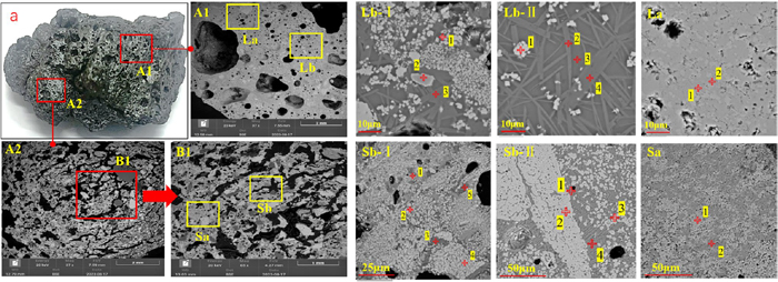
Fig. 8. SEM-EDS analysis of the product sinter (a-product sinter; A1-liquid phase region; A2-pellet region; B1-local magnification of A2; La-magnification of particles in A1; Sa-magnification of particles in B1; Lb-I, Lb-II: magnification of liquid phase in A1; Sb-I, Sb-II: magnification of liquid phase in B1). (Online version in color.)
Table 5. The results of the EDS analysis for
Fig. 8.
| Area | Elemental compositions/(wt, %) | Mineral phase |
|---|
| O | Mg | Al | Si | Ca | Mn | Fe |
|---|
| La | 1 | 10.77 | 0.00 | 0.00 | 0.17 | 0.86 | 63.42 | 24.78 | Bixbyite |
| 2 | 10.82 | 0.00 | 0.13 | 1.69 | 3.51 | 62.92 | 20.94 | CaO·Mn2O3·Fe2O3 |
| Lb-I | 1 | 12.47 | 0.61 | 2.1 | 4.38 | 2.45 | 61.63 | 16.35 | Hausmannite |
| 2 | 14.3 | 1.95 | 5.04 | 0.00 | 0.28 | 45.32 | 26.84 | Bixbyite |
| 3 | 14.73 | 1.47 | 0.56 | 25.76 | 15.47 | 40.91 | 1.1 | Tephroite |
| Lb-II | 1 | 11.31 | 0.42 | 0.32 | 0.22 | 0.33 | 54.39 | 33.01 | Bixbyite |
| 2 | 15.87 | 1.06 | 2.22 | 24.9 | 10.65 | 43.56 | 1.73 | Tephroite |
| 3 | 16.72 | 0.68 | 6.63 | 25.76 | 9.58 | 36.38 | 4.25 | Glass |
| 4 | 15.2 | 1.17 | 0.37 | 25.16 | 12.14 | 44.91 | 1.06 | Tephroite |
| Sa | 1 | 11.05 | 0 | 0 | 0 | 0.18 | 43.88 | 44.89 | Bixbyite |
| 2 | 12.25 | 0 | 0 | 4.2 | 2.99 | 75.5 | 5.05 | Hausmannite |
| Sb-I | 1 | 14.39 | 1.3 | 0 | 13.03 | 2.46 | 67.58 | 1.23 | Tephroite |
| 2 | 12.48 | 0.34 | 1.17 | 1.48 | 0.68 | 67.12 | 16.72 | Hausmannite |
| 3 | 15.12 | 0.64 | 4.53 | 20.84 | 11.9 | 41.74 | 5.23 | Glass |
| 4 | 10.69 | 0.24 | 0.28 | 2.44 | 3 | 64.79 | 18.55 | Hausmannite |
| 5 | 15.6 | 0.89 | 3.91 | 23.46 | 11.38 | 42.46 | 2.31 | Glass |
| Sb-II | 1 | 13.87 | 1.11 | 2.97 | 21.43 | 7.33 | 50.87 | 2.42 | Tephroite |
| 2 | 10.9 | 0.33 | 0.43 | 0.76 | 1.28 | 66.55 | 19.75 | Hausmannite |
| 3 | 11.71 | 0 | 1.4 | 1.47 | 1.41 | 58.6 | 25.42 | Bixbyite |
| 4 | 13.68 | 0.96 | 2.96 | 19.48 | 7.81 | 50.62 | 4.51 | Glass |
Regardless of the origin of the product sinter, the main composition of the glass phase is calcium alumino silicate (CaO·Al2O3·Mn2O3·Fe2O3·SiO2). Furthermore, the glass phase still contains a significant amount of uncrystallized manganese elements, which, as a refractory phase, is not conducive to subsequent smelting processes.
The distribution of elements in the liquid phase region and spherical product sinter can be seen in Figs. 9 and 10. The product sinter at different locations contains partially mineralized mineral particles. It is worth mentioning that the overlapping effect of manganese and iron elements in the particle distribution area of the spherical product sinter (as shown in Fig. 8) is lower than that of silicon element. This may also suggest that this area is more inclined to form manganese ferrotephroite. Meanwhile, both in the liquid phase region and in the spherical product sinter, there is a high degree of overlap in the distribution of manganese and iron elements in the mineralized areas, indicating that Fe2+ has entered the lattice of manganese minerals. Interestingly, aluminum elements are primarily dispersed in the glass phase, both in the liquid phase region and in the spherical product sinter.

Fig. 9. The distribution of elements in the ordinary liquid phase region. (Online version in color.)

Fig. 10. The distribution of elements in the spherical product sinter. (Online version in color.)
As is well known, although the overall atmosphere during the sintering process is oxidizing, the areas with high coke content often have a weak reducing atmosphere. Some researchers have found that the CO content in the flue gas during the sintering of manganese ore can reach 7.5%.38,39) This suggests that high-valence manganese minerals may gradually be reduced to low-valence manganese compounds during the sintering process. Combined with Figs. 1 and 5, MnO2 in the raw ore may be sequentially reduced to Mn2O3, Mn3O4, and MnO.39,40,41) Additionally, Fe2O3 may reduction to magnetite in the sintering process. The specific chemical reactions are represented as Eqs. (1), (2), (3), (4), (5).
|
3F
e
2
O
3
+CO=2F
e
3
O
4
+C
O
2
| (2) |
|
2Mn
O
2
+CO=M
n
2
O
3
+C
O
2
| (3) |
|
3M
n
2
O
3
+CO=2M
n
3
O
4
+C
O
2
| (4) |
|
M
n
3
O
4
+CO=3MnO+C
O
2
| (5) |
Mineralogical analysis and SEM-EDS analysis have revealed the formation of numerous manganese-iron spinel phases in the product sinter. This is due to the close ionic radii of Mn2+ (0.91 Å), Fe2+ (0.83 Å), and Fe3+ (0.67 Å), which facilitates mutual substitution reactions at higher temperatures.42,43) The specific reaction steps are represented as Eqs. (6) to (7).
|
F
e
3
O
4
+M
n
3
O
4
→F
e
x
M
n
3-x
O
4
| (6) |
|
F
e
3
O
4
+MnO→F
e
x
M
n
3-x
O
4
| (7) |
As important crystalline phases in the liquid phase, the formation of ferrotephroite and pyroxene phases primarily occurs through the reaction between manganese-bearing minerals and silicate minerals. The specific reaction process is represented as Eqs. (8), (9), (10), (11), (12), (13). Due to the presence of a large amount of SiO2 in the sintering feed, it readily reacts with newly formed MnO and Fe3O4 in the high-temperature environment of sintering, resulting in the formation of Mn2SiO4 and Fe2SiO4 melts.44,45) These melts eventually crystallize into ferrotephroite or pyroxene after cooling.
|
2MnO+Si
O
2
=M
n
2
Si
O
4
| (8) |
|
2F
e
3
O
4
+Si
O
2
=F
e
2
Si
O
4
+2F
e
2
O
3
| (9) |
|
MnO+F
e
3
O
4
+Si
O
2
→
(
Fe, Mn
)
2
Si
O
4
| (10) |
|
M
n
2
Si
O
4
+F
e
2
Si
O
4
→
(
Fe, Mn
)
2
Si
O
4
| (11) |
|
M
n
2
Si
O
4
+CaO→(
Mn,Ca
)
Si
O
3
| (12) |
|
M
n
2
Si
O
4
+A
l
2
O
3
→M
n
3
A
l
2
(
Si
O
4
)
3
| (13) |
3.3.4. Phase Diagram Analysis
It has been reported in literature that the traditional sintering of manganese ore fines has the characteristics of large amount of coke level (5%–10%), high solid fuel consumption (100 kg/t–300 kg/t), and poor sintering performance of product sinter. Some scholars explain that this is due to a low amount of low-melting substances formed in the sinter.46,47) In order to investigate the reasons for the reduction in solid fuel consumption and the enhanced strength of the sinter processed by pellet-sintering, the binary phase diagram Fe2O3–MnO2 was used to describe the mineralization process of pellet sintering. As shown in Fig. 11(a), the lowest melting temperature of (MnO·Fe2O3+Fe2O3) is as high as 1750°C, making it difficult to achieve in the normal sintering process with lower coke breeze dosage. Meanwhile, it can be seen in Fig. 11(d) that the maximum temperature of thermocouple No. 1 and No. 2 is 1277.6°C and 1326°C respectively. This also suggests that the large amount of liquid phase in the pellet sintering process may not be generated from the melting of (MnO·Fe2O3+Fe2O3). Considering the presence of ferrotephroite, pyroxene, and spinel phases in the actual liquid phase of sintered ore, as well as the distribution of elements in the glass phase, it is speculated that the primary liquid phase formed during pellet sintering is derived from the reaction between silicates and manganese ore, resulting in the formation of low-melting substances. As shown in Fig. 11(b), the ternary phase diagram of the Fe2O3–MnO–SiO2 system also confirms this conjecture, where the presence of pyroxene, ferrotephroite, and spinel phases can be observed at 1300°C in the ternary system.

The combustion zone in the sintering process will generate a liquid phase region.48) A large amount of low-melting compounds reacted with high-melting minerals in sintering to form low-melting eutectics. The surrounding area of large particles melts, resulting in the formation of a low-eutectic mixed liquid phase. The components in the liquid phase undergo substitution, oxidation, reduction, and other reactions at high temperatures. It can be observed from Fig. 11(b) that there is a low-melting region near the composition of 43.4% MnO and 15.2% Fe2O3, and the main bonding phases in the liquid phase are spinel, ferrotephroite, and pyroxene.
Based on phase diagram analysis, the primary low-melting compounds formed by silicates dominate the initial liquid phase in pellet sintering. The main bonding phases in the liquid phase are manganese ferrotephroite and manganese iron spinel. This is similar to the acidic sintering of low-iron manganese ore fines, where the main phases are hausmannite (Mn3O4), manganosite (MnO), and manganese silicates (2MnO·SiO2, MnO·SiO2). When the amount of iron oxide increases in the manganese ore sintering system, the main bonding phases will transition to manganese iron spinel or iron-manganese oxide (FexMn3-xO4). This also indicates that the content of iron oxide has a significant impact on the formation of the main mineral phases in the liquid phase of the sintered ore.

