Abstract
Addressing the threat of global climate change is an urgent priority for all industries. The Paris Agreement set the global long-term goal of carbon neutral by 2050 for all member countries. As the steel industry occupies approximately 7.2% of the total global greenhouse-gas emissions, innovative technologies that build upon or move beyond the past developments are desired to reach this long-term goal. Various zero carbon technologies have been proposed for the steel industry. This review focuses on the current state of the steel industry from the perspective of long-term targets and pathways for the future. The design of an optimal ironmaking process for low carbon and decarbonization is discussed from a technological perspective, considering comprehensive consistency with sustainability in the steel industry. In particular, perspectives on the hydrogen-based ironmaking process using renewable energy for carbon direct avoidance and smart carbon usage are described.
1. Introduction
The Paris Agreement, which came into effect in 2015, set the goal of limiting the global average temperature rise to well below 2.0°C, preferably 1.5°C, above pre-industrial levels.1) To achieve this target, each country submitted its Nationally Determined Contribution, which is a self-defined pledge for meeting the long-term goals of carbon neutrality and net-zero emissions by 2050. Each country has proposed specific greenhouse gas emission reduction measures to meet this goal, and various industry sectors have set individual numerical targets for 2050 based on their technological structures. As the total of the numerical targets of all sectors is directly linked to achieving the global greenhouse gas emission target, the individual targets of each sector are attracting attention.
Carbon is the main reducing agent and energy source for steelmaking, with the steel industry accounting for approximately 7.2% of the global greenhouse gas emissions, as shown in Fig. 1.2) Specifically, it generates approximately 3.1 Gt/y of carbon dioxide emissions, thereby having a large influence on global warming. On the other hand, the steel industry is essential for providing a stable supply of various steel products to society, and as it is a large-scale industry with rationally structured production process, its smooth transition to CO2 mitigation is challenging. Particularly, it features a long investment cycle due to the extensive process lifespans compared with other sectors and requires substantial investments for process modifications. Thus, future strategies must be developed and smoothly implemented from an early stage. Various terms are used to define the targets for 2050, such as carbon neutrality, zero emissions, zero carbon emissions, and net-zero emissions. Carbon neutrality is appropriate for a comprehensive overall evaluation of an industry; however, most CO2 emissions in the steel industry are categorized as Scope 1, and although it also involves Scope 2 and 3 emissions, the primary goal is to pursue zero carbon and emissions in steel production; therefore, in this review, zero carbon and zero emissions are used to express the target achievement.

Historically, the steel industry has been crucial for supplying socially beneficial materials and contributed to economic development through large-scale production capabilities by establishing efficient production processes and supporting national development. However, because it depends on carbon as a reducing agent and energy source, its production activities are directly linked to CO2 generation and account for a large proportion of greenhouse gas emissions. As global crude-steel production is expected to continue increasing, the steel industry must make further efforts to address global warming to meet the 2050 goals while continuing to provide steel products.
As mentioned above, the current ironmaking process uses naturally available carbon from fossil fuels as a reducing agent and energy source for the mass production of steel products. Although CO2 is unavoidably generated during the reduction of iron ore, it is necessary to mitigate the carbon dependence for reducing agents and heat sources and employ large-scale processes that can help meet the future goal of zero carbon. As rapid green transformation is challenging, a feasible pathway leading up to 2050 from a global perspective, while maintaining consistent resource, energy, and product supplies is urgently required. This review comprehensively presents the current circumstances, recent trends in ironmaking technology development based on the aforementioned situations, and a prospective future pathway toward zero carbon emissions.
2. Current State of the Steel Industry
2.1. Current Ironmaking Processes
The current ironmaking process can be categorized into the blast furnace process, direct reduction process, and scrap melting using an electric arc furnace (EAF), as shown in Fig. 2. In 2023, the global crude-steel-production rate was approximately 1.89 Gt/y.3) Among them, the blast furnace process accounts for 71% of crude steel production owing to its suitability for mass production. Direct reduction process primarily involves a shaft-furnace process that employs reformed natural gas as a reducing agent and emits approximately two-thirds of the CO2 than a blast furnace using hydrogen-rich gas. Although this process has been limited to areas where natural gas is available, in recent years, its usage has been expanding and has reached 137 million tons/y. Scrap melting via EAF does not involve iron-oxide reduction and emits one-third of the CO2 compared with blast furnace process Therefore, it is a promising method for reducing CO2; however, it entails reusing steel materials containing trump elements, which have limitations in both their usage and supply.

Fig. 2. Various ironmaking processes for crude steel production. (Online version in color.)
In large-scale process industries such as steel industry, it is nearly impossible to convert the conventional production system to a decarbonized one in a single step for meeting the future zero carbon aims, which is not possible through incremental improvements. The currently employed blast furnaces will eventually need to be relined, whereas hydrogen can be employed in the direct-reduction process as it involves gas-based reduction. Therefore, a comprehensive understanding of the current process characteristics is crucial for developing a future process vision that can respond to the current situation and help establish a continuous pathway for the future.
2.2. Significance of Future Green Transformation
Compared to other industries, the steel industry involves a long capital reinvestment cycle with considerable retrofitting. To ensure efficient steel production, the scale of the facilities employed has expanded significantly and stable long-life operations have been maintained. Additionally, renovating major production facilities such as blast furnaces is extremely costly and their retrofitting requires long-term capital investment plans. Steelworks is an industrial plant that collectively involves various functions and complex processes. To smoothly move toward the goal of achieving zero carbon, a planned transformation must be implemented.
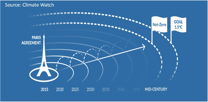
Figure 3 shows the blast furnace capacity to be reinvested considering reaching end-of-life as indicated by Agora Industry and Wuppertal Institute for Climate, Environment and Energy.4) By 2030 more than 70% of existing blast furnaces will reach the end of their campaign life and require reinvestment. The current lifespan of blast furnaces is approximately 25 years and blast furnaces are expected to be due for relining in succession. If the reinvestment is limited to the past retrofit level, zero carbon cannot be achieved, leading them to become stranded assets. Therefore, to achieve the zero carbon aim by 2050, stakeholders will have to decide by 2030 on whether to replace blast furnaces with new technologies such as hydrogen-based processes to smoothly achieve this goal. Figure 4 shows a schematic picture from the Paris Agreement to 2050 provided by Climate Watch.5) The actual situation depends on the industry characteristics. Considering the long-term reinvestment cycle and requirement of smooth conversion of the steel production system, 2050 can be considered as the “near future” in the steel industry.

3. Pathway to Zero Carbon in the Steel Industry
3.1. Annual CO2 Emissions Trajectories up to 2050
Based on the current technological scenarios, several research organizations have proposed the annual CO2 emission trajectories desired up to 2050. As a representative example, three macroscopic scenarios, including baseline, technology moratorium, and carbon cost, proposed by the Mission Possible Partnership (MPP) with the goal of net zero by 2050 are shown in Fig. 5.6) Baseline represents a case wherein proactive investments are not made due to switching costs, whereas carbon cost represents an ambitious technology-adoption scenario to achieve zero carbon by proactively shifting to new processes to reduce CO2 emissions and introducing innovative technologies. Finally, technology moratorium is an intermediate scenario that involves introducing technologies cautiously, and the time required for the effects to show is different from that of carbon cost. Carbon dioxide removal (CDR) refers to the target changes once the effects of carbon offset start showing. The carbon cost scenario is similar to the NZE (Net Zero Emissions) proposed by the International Energy Agency (IEA).7) Additionally, although both carbon cost and technology moratorium scenarios are aimed at achieving zero carbon by 2050, major countries, including industrial countries, have set intermediate targets of reducing CO2 by 30% or more by 2030. As the steel industry is related with a large proportion of CO2 emissions, it is essential to put it on course for achieving these targets as soon as possible.

Figure 6 shows the pathway toward zero carbon for the ironmaking industry based on its current production framework.8) These directions include smart carbon usage (SCU), which involves the aggressive pursuit of decarbonization and low carbon for existing processes such as blast furnaces by employing CO2 capture and utilization (CCU), wherein the emitted CO2 is reused as a raw material. Sometimes, CCU is used within the concept of SCU. The other way is a sliding shift away from blast furnace to hydrogen-based ironmaking for carbon direct avoidance (CDA) by employing green hydrogen. In hydrogen-based ironmaking, the effect of CO2 reduction depends on the hydrogen production quality; therefore, it is represented as CDA equivalent to the direct effects of decarbonization.

Fig. 6. Relative CO2 emissions in various processes and directions to CO2 mitigation. (Online version in color.)
Considering the maturity of technology and time to realization, a path must be traced as a visual flow that continuously connects the present to the future. Although various path can be considered, a time-series general development flow is exemplified in Fig. 7. Furthermore, scrap utilization is a valuable method for developed countries; however, its use remains restricted because of limited supply of scrap materials. Therefore, realistic measures include the development of SCU, which involves the efficient utilization of carbon and carbon-input reduction by combining the current ironmaking processes and CCU, which effectively reduces the use of fossil raw materials to source carbon. The next stage involves replacing carbon-based reduction with hydrogen-based ironmaking process, wherein hydrogen is employed as the reduction agent. Utilizing the approaches employed in the existing natural gas-based direct-reduction process, which is well-developed, can be a promising long-term approach. However, pure hydrogen does not exist in nature on Earth and must be artificially produced. Typically, it is produced via water electrolysis; however, as this process requires a considerable amount of renewable energy, hydrogen production using stable clean energy is necessary for its widespread adoption.

Fig. 7. Macroscopic roadmap to zero carbon through low carbon and decarbonization. (Online version in color.)
As described before, although SCU and CCU are realistic extensions of the current processes for smart carbon usage, their CO2 reduction performance faces certain limitations. Zero carbon can be effective only when technology is widespread in the industry. Considering their maturity, the time required for their industrialization, and advancements in clean-energy supply, a rational combination of CDA, SCU, and CCU is expected to be the most effective strategy.
3.3. Design of Ironmaking Process to Zero Carbon
Agora Industry and Wuppertal Institute for Climate, Environment and Energy have presented specific process configurations for the steel industry to achieve the zero carbon goals. Figure 8 shows the specific process ratios that should be achieved by 2050 based on various technology deployments proposed by these above organizations.9) The two cases, technology mix and global green iron, are shown in Fig. 8, both of which consider proactive improvements in the future. The pathway of technology mix is similar to the technology moratorium scenario shown in Fig. 5, wherein technologies are introduced cautiously. Global green iron is the ideal scenario for achieving zero carbon emissions. Both scenarios show gradually reducing the utilization of the blast furnace process, despite the expected enhancements to the process. The current direct reduction process by natural gas is predicted to be replaced by H2-DRI (hydrogen-based ironmaking). Although this report states that bioenergy with carbon dioxide capture and storage (BECCS) and molten oxide electrolysis (MOE) will occupy specific ratios, these technologies are currently in the fundamental development stage and their advantages remain unknown. On the other hand, the NZE scrap-EAF is highly anticipated.

Figure 9 shows the future iron-ore consumption ratios of both direct reduction and blast furnace processes proposed by Mission Possible Partnership.6) Evidently, the blast furnace will be gradually replaced by H2-DRI comprising both DRI-EAF and DRI-Melter-BOF. Here, DRI-EAF and DRI-Melter-BOF include the current DRI and the future hydrogen-based ironmaking. Although these reports are different for each other, they predict a progressive shift from blast furnaces to hydrogen-based ironmaking through the improvement of blast furnaces through strategies such as SCU and CCU.
3.4. Proposed Process Initiatives and Projects
Various process modifications regarding SCU, CCU and CDA have already been proposed for the concrete industry to meet the zero carbon goals and are being implemented globally. An overview of the projects that are being currently implemented and the classification of the processes employed is shown in Fig. 10. In the area of SCU and CCU, various techniques, such as hydrogen-rich gas injection, reducing gas shaft injection, and carbon recycling, for reducing the carbon input into blast furnaces have been proposed, and some processes, such as coke oven gas (COG) injection, have been implemented. The details regarding SCU are described in the next section. Typical examples of CCU projects include Carbon2Chem by thyssenkrupp and Steelanol by ArcelorMittal.10,11,12) Both methods convert the off-gases containing CO2 emitted from steelworks into chemical products and fuels. Carbon2Chem primarily produces methanol, which thyssenkrupp also refers to as a cross-industrial network and emphasizes that it is not hard CO2 capture but “Integrated CO2 Capture” that involves optimizing the capture of the substantial off-gases emitted from steelworks and other industries.10,11) ArcelorMittal and LanzaTech in the United States has developed Steelanol, a technology that produces ethanol from steelworks gas through fermentation,12) with a semi-commercial plant being operated at the ArcelorMittal Ghent plant and another similar plant is operated by Shougang Steel, China. Moreover, although biomass is attracting attention as a carbon-neutral raw material, it features low energy density and has a negligible carbon-replacement effect. A promising method for improving the properties of biomass is torrefaction, which semi-carbonizes it in an oxygen-free atmosphere at approximately 300°C. It not only enhances the energy density of biomass but also makes it easier to crush, allowing it to be pelletized for mass transportation. The concept of Steelanol and biomass-utilization employed by ArcelorMittal are illustrated in Fig. 11.12)

Fig. 10. Projects in progress and process classification. (Online version in color.)
Hydrogen-based ironmaking is the most representative method for decarbonization, and as mentioned above, it fundamentally involves a highly refined direct reduction process using a shaft furnace. Initially, natural gas was employed; however, in some countries, this process is at the investment stage with the aim of employing it for hydrogen-based ironmaking in the future. Besides shaft furnace, POSCO and Primetals Technologies are also developing alternate fluidized-bed hydrogen-reduction processes that do not require iron-ore preprocessing.13,14)
4. Further Improvements of Blast Furnace
4.1. Advanced Blast Furnace for Further Mitigating CO2
The detailed energy flow of an integrated steelworks based on blast furnace is divided into two parts: the upstream process of ironmaking and the downstream process for manufacturing products, as shown in Fig. 12, wherein coal is the main source of energy and reductant and 22–24 GJ/t of energy is required as the input. Approximately 70–80% of the energy is consumed for ironmaking, whereas about 5 GJ/t is supplied to the downstream process as blast furnace and coke oven gases, making it a self-sustaining process.15) Additionally, the amount of carbon required is significantly affected by the blast-furnace operation. The CO2 emission is evaluated based on the boundary shown in Fig. 12. Traditionally, energy consistency has been emphasized; however, by eliminating this constraint, carbon reduction can be prioritized by adopting clean energy, leading to the development of CO2 reduction processes for blast furnaces. As shown in Fig. 12, several processes around blast furnace can be proposed.

Fig. 12. Total energy flow in the integrated steel works. (Online version in color.)
The overall process for reducing CO2 in a blast furnace process is shown in Fig. 13. Hot briquetted iron (HBI) charging is one example for reducing blast-furnace emissions. Although this method has already been implemented in the United States, voestalpine16) and Kobe Sreel17) have conducted large-scale HBI charging tests for reducing CO2 emissions from blast furnaces. In particular, recently, Kobe Steel has carried out the test trial on HBI charges up to 440 kg/t in a blast furnace at their Kakogawa steelworks and reported a 25% CO2 reduction in 2023.17) Generally, as the amount of metallic iron increases, the direct reduction ratio of the furnace decreases, resulting in a decrease in the specific gas volume, leading to insufficient heat supply in the upper part of the blast furnace; however, this issue can be resolved through nitrogen enrichment.17) Besides metallic iron charge, several methods such as top-gas recycling and reducing gas shaft injection have been proposed as shown in Fig. 13. Ultra-low CO2 steelmaking (ULCOS) is a typical example of a top-gas recycling system,18) whereas dry-gas reforming involves reforming CH4 with CO2; this method was verified by Nippon Kokan (NKK) in an experimental blast furnace in the 1970s.19) The origins of these fundamental technologies have already been identified in the history of ironmaking. Although these technologies have actively been developed at the time, the reduction of the coke ratio was the main purpose from the viewpoint of economic efficiency; however, recently, in order to mitigate CO2 emissions, Paul Wurth has newly proposed the EASyMelt (Electrically Assisted Syngas sMelter) technology20) and Baowu Steel has proposed the HyCROF (Hydrogen-enriched Carbonic Oxide Recycling Oxygenate Furnace), a technology that adds hydrogen injection to the top-gas recycling.21) The details of EASyMelt and HyCROF will be described later. Moreover, a method of injecting the most amount of hydrogen-rich gas, such as COG, from the tuyere has been proposed, and JFE Steel has proposed a method of synthesizing methane from the CO2 in the top gas using hydrogen and injecting it again into the blast furnace for carbon recycling.22) In contrast to reforming, methane synthesis is a high-pressure reaction wherein H2 is used to split CO2. This reaction is exothermic; therefore, a total evaluation should include both the energy and hydrogen used. These above processes are applicable to oxygen blast furnace (OBF) to enhance the combustion conditions at the tuyere and produce N2-free top gas. Thus, various technological advancements have been made in the OBF process and can be implemented with partial or additional modifications to the blast furnaces. Additionally, they are being employed and validated in both small and commercial blast furnaces, and the visual overview of on-going projects is shown in Fig. 14. The details of the injection systems and the test scale are shown in Fig. 14.

Fig. 13. Improved technologies to reduce CO2 emissions in blast furnace. (Online version in color.)

Fig. 14. Various projects to reduce CO2 emissions in blast furnace. (Online version in color.)
In Japan, the Japan Iron and Steel Foundation is conducting research and development as a part of the Green Innovation Project of the government and three blast furnace companies participate by the support of NEDO (New Energy and Industrial Technology Development Organization).23) This is a parallel research and development project that will run until 2030 and involves advancements such as hydrogen injection into blast furnaces, carbon recycling, hydrogen-based ironmaking, electric furnaces, and melters, with rapid implementation planned after successful testing.
4.2. Recent Representative Developments of Advanced Blast Furnace
The commercialization of HyCROF, developed by Baowu Steel, is being verified at its subsidiary Bayi Iron & Steel. Bayi Iron & Steel first conducted tests in a small blast furnace of 430 m3, and the process flow is shown in Fig. 15.21) Thanks to the use of an OBF, the productivity is 4.5–5.0 t/m3d, twice that of a normal blast furnace, and the coke rate is under 290 kg/t. Additionally, the CO2 reduction was estimated to be 21% in the initial stage, and to further enhance it, HyCROF is also experimenting with electric heating, such as plasma heating of reducing gas. Based on the positive results, they are proceeding with verification in a 2500 m3 blast furnace in 2024.

As described above, EASyMelt process aims to achieve the ultimate goal of low carbon blast furnaces through the production of reducing gas by dry reforming methane derived from natural gas or COG with CO2 and injecting it into the shaft or tuyere of the blast furnace.20) Although it employs an OBF, it aims to heat up the reducing gas by plasma. Its conceptual process flow is shown in Fig. 16, wherein the target coke rate is 100–180 kg/t, which corresponds to an approximately 60% CO2 reduction. The offline gas-reforming experiments have already been conducted by Paul Wurth and comprehensive verification is being conducted at Tata Steel 600 m3 blast furnace in Jamshedpur, India. The concrete image in the industry scale of EASyMelt is shown in Fig. 17.24)

In the aforementioned both processes, the use of plasma with clean electricity as an efficient heat source is also being investigated to substantially reduce the coke ratio. By partially replacing coke with plasma-based clean electricity as the heat source, the coke ratio can be minimized, leading to a reduction in CO2 emissions. Therefore, both the HyCROF and EASyMelt processes aim to achieve the goal of low carbonization in existing blast furnaces as much as possible and are expected to be commercialized soon.
5. Development of Hydrogen-based Ironmaking
5.1. Basic Concept of Hydrogen-based Ironmaking
Shaft furnaces and fluidized-bed reactors are promising approaches for hydrogen-based ironmaking processes; however, the shaft furnace is preferred owing to its high efficiency by the counter-current system that allows it to attain high metallization. The concept of the conversion from blast furnace to hydrogen-based ironmaking by shaft furnace is illustrated in Fig. 18. The shaft furnace is similar to the upper part of the blast furnace with a high solid-gas contact efficiency, and the gas source is changed to green hydrogen. The lower part of the blast furnace melts iron ore and separates slag, which can also be done using a smelter or EAF to produce hot metal or liquid steel. A smelter is similar to the lower part of the blast furnace and the final reduction and carburization are conducted in a reducing atmosphere. The melting of DRI plays a major role in EAF. Furthermore, the differences in iron ore grade influence both processes, as described in subsequent sections. Thus, a combination of shaft furnace and smelter can reproduce the functions of a blast furnace without requiring carbon as reducing agent.

Fig. 18. Conversion from blast furnace to hydrogen-based ironmaking. (Online version in color.)
The shaft furnace for hydrogen-based ironmaking has commonality with the current shaft furnace technology for DRI. Typical DRI processes such as MIDREX and ENERGIRON are shown in Fig. 19. They differ in terms of the gas reforming and operating pressure employed. Both processes have a long history of DRI productions and a maximum production of 2.5 Mtpy (Million tons per year) has been achieved. In ENERGIRON, H2 content already reaches 70–80% owing to steam reforming. The direction for future hydrogen-based ironmaking involves using these highly mature natural gas-based DRI technologies.

Fig. 19. Current direct reduction processes of MIDREX and ENERGIRON. (Online version in color.)
In addition to hydrogen-based shaft-furnace technology, the hydrogen reduction process in a fluidized bed is being developed in the projects such as Hydrogen Reduction Ironmaking (HyREX) by POSCO13) and Hydrogen-based Direct Reduction (HyFOR) by Primetals Technologies.14) Although fluidized-bed processes can directly use iron ore without pelletizing, they are not yet widely used in current DRI processes.
Figure 20 presents an overview of the on-going DRI projects that have been proposed or constructed, which can be considered as the foundation of hydrogen-ready ironmaking. Currently, most processes are based on natural gas or COG, and in the future, hydrogen-based ironmaking will be implemented once a stable hydrogen supply has been established. Plants already in operation include Zhangjiakou of Hebei Iron and Steel (HBIS)25) and Zhanjiang of Baowu Steel,26) with capacities of 0.6 and 1.0 Mtpy, respectively, and the 2.5 Mtpy capacity plant of thyssenkrupp under construction in Germany.27) Moreover, newcomers such as H2 Green Steel (Currently, Stegra) in Sweden28) and Blastr Green Steel,29) which are aiming to implement hydrogen ironmaking from the outset, are attracting attention as new business models for steel product users from the conceptual stage.

Fig. 20. On-going projects aiming at hydrogen-ready CO2 reduction process. (Online version in color.)
Although the hydrogen-based ironmaking by shaft furnace is attractive, there are also some subjects to deploying shaft furnaces for hydrogen-based ironmaking, as shown in Fig. 21. The first is the supply of hydrogen from renewable sources, with water-electrolysis technologies being the primary focus. These include proton exchange membrane, alkaline water electrolysis, and solid oxide electrolyser cell processes; however, they are still under development and will require some time for development and testing before being employed in industry-scale plants. Additionally, a pellet plant is required for shaft furnaces and carbon-free pellet firing is desirable. Therefore, using biomass-derived fuel and producing of non-sintered agglomerates have been proposed as suitable alternatives.

Fig. 21. Subjects of hydrogen-based ironmaking process. (Online version in color.)
Another issue is maintaining the heat balance in the shaft furnace due to the endothermic reaction via hydrogen reduction. However, looking at the whole process, the concept of heat flow ratio in shaft furnace is fundamentally different from that in blast furnace. Blast furnaces employ a single gas pass, wherein the heat-flow ratio affects the temperature profile, whereas shaft furnaces employ gas circulation system, wherein heat absorption can be compensated for by strengthening the gas circulation system. For example, MIDREX type DR process features an inlet gas volume of approximately 1664 Nm3/t when using natural gas to produce a reforming gas, whereas it can offer an inlet gas volume of 2480 Nm3/t for hydrogen-based ironmaking.30) Engineering company, such as Tenova HYL, has already verified its operation under 90% H2 conditions in small-scale plant,31) and hydrogen-based heat absorption can be implemented by adjusting the operating conditions. Moreover, sticking is likely to occur in shaft furnaces; however, mechanical devices, such as cluster breakers, can be employed to avoid it. MIDREX has implemented countermeasures for this by installing three-stage cluster breakers called burden feeders. Another key consideration during the design process is the selection of the EAF or smelter for application after the shaft furnace. The items such as slag properties on each process are described in the next section.
The fluidized-bed process features unique characteristics such as the direct use of iron ore without pelletizing. However, the fluidized bed is a perfect mixing-type reactor, and to enhance reduction, it is necessary to increase the number of stages to three or four, with a focus on preventing sticking. In HyREX and HyFOR, the reduction by H2 is intentionally conducted at low temperatures of 600–700°C to avoid sticking. Therefore, measures to maintain a low temperature are necessary. In HyREX, oxygen is introduced halfway through the process, whereas in HyFOR, the preheating reactor is prepared before the fluidized beds and the sensible heat of the preheated ore fines constitutes the endothermic reaction.
5.3. Features of Smelter and EAF
The differences between the smelter and EAF compared with the blast furnace are summarized in Table 1. Basically, iron resources of DRI are different from each other. Here, BF-grade pellets imply the pellets used for blast furnace. EAF employs radiation heating by arc between electrodes and features excellent melting power; however, it features an oxidizing atmosphere during the discontinuous operation and outputs liquid steel and oxidized slag. The slag basicity is high (1.9–2.0) for the sake of slag foaming and the electrodes are made of pre-melt graphite. By contrast, a basic concept of the smelter is derived from the submerged arc furnaces used for non-ferrous smelting and employ a reducing atmosphere in a closed furnace and self-baking electrodes (Söderberg electrodes). Carbon is charged into the smelter for carburization. The basic heat source is the resistance heating of the slag. Additionally, a short-arc or brush-arc mode is employed during continuous operation. These modes can enhance the melting ability and carburization, then, the load resistance for electrode is little affected by the slag properties. The smelter is a continuous furnace that employs the same tapping process as that in a blast furnace, which has the final reduction ability. The smelter product is a hot metal, wherein the carbon content can be adjusted via carbon addition through carburization to metal. The hot metal is then highly refined in the subsequent BOF (Basic Oxygen Furnace) process to produce liquid steel. One issue is that it is a two-dimensional furnace that mainly uses resistance heating, which makes it difficult to scale up, with the maximum capacity to date estimated at 1.2 Mtpy. Although it is generally referred to as a smelter in Table 1, various practical names, such as open bath furnace, open slag bath furnace, or electric smelting furnace are used, depending on the developers. Sommerfeld et al. have intensively categorized smelters based on non-ferrous metal processes as historical evaluations of their use as industrial furnaces for ferrous materials is insufficient.32) Currently, engineering companies are operating pilot plants and have developed various designs of the smelter.33,34)
Table 1. Characteristics of EAF and Smelter compared with blast furnace. (Online version in color.)
Another crucial issue to be considered when comparing smelters and EAF is iron-ore resource responsibility via shaft furnace. The EAF features high basicity and as the amount of gangue increases, the slag volume increases sharply, converting it into an oxidized slag from which iron flows away as FeO. Therefore, EAF preferably requires DRI derived from high-grade pellets to reduce the amount of slag as shown in Table 1. In the DRI-EAF route, pellets with an iron content of ≥67% are preferred.35) However, there are almost few high-grade pellets suitable for the maritime transport considering the future expansion. The amount of high-grade pellets is estimated to be approximately 3% of the sea-borne iron-ore. Thus, DRI-EAF has limitations due to the limited high-grade pellet supply.
The smelter has a reducing atmosphere with a basicity of approximately 1.1, which is roughly the same as that of a blast furnace owing to the separation and fluidity of hot metal and slag. The FeO content in the smelter slag is equivalent to that in a blast furnace and the iron yield is high. Additionally, the slag can be granulated and used as a raw material for cement. Although the whole process comprises two stages, the smelter offers advantages in terms of the iron ore resource flexibility and connections with the currently employed steelmaking process. For the future expansion toward hydrogen-based ironmaking, the process design must be based on easily available raw materials such as BF-grade pellets. This is a realistic conversion method that can take advantage of future resource trends. As shown in Fig. 22, Primetals Technologies has offered a visual comparison of the cost and slag ratio of iron-ore grade and EAF or Smelter-BOF method. From the perspective of resource response capacity and costs, 67% is the threshold.35) The total costs indicate that the DRI-smelter-BOF is cost-effective for low-grade ores, whereas DRI-EAF is preferable for high-grade ores.

Figure 23 shows the summary of the process configurations for iron ore resource responses. For BF-grade pellets, a combination of a shaft furnace and smelter, as shown in Fig. 23(a), is suitable. For fluidized beds that eliminate preprocessing requirements, such as pellet plants, and directly use sinter feed and fine ore, the process shown in Fig. 23(b) is appropriate, whereas for high grade pellets, that shown in Fig. 23(c) is applicable. Although the smelter involves two stages, the next process, BOF, allows achieving the same remarkable refining as that available currently, making it suitable for high-quality steel production. Considering a stable iron ore supply in the future and its application to actual steelworks, the shaft furnace and smelter-BOF combination is favorable. This one-step process using EAF is expected to be profitable for greenfield plants with access to high grade pellets.

Fig. 23. Optimum hydrogen-based ironmaking process from the viewpoints of iron ore grade. (Online version in color.)
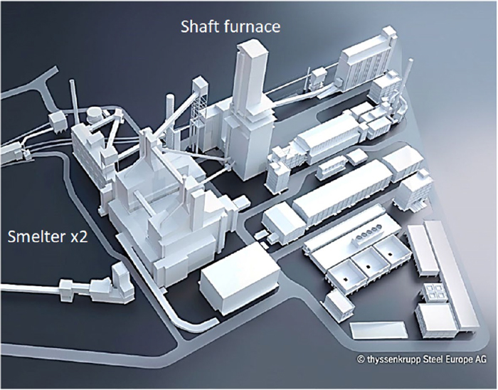
thyssenkrupp has proposed a hydrogen-based ironmaking process that combines a direct-reduction shaft furnace and smelter. Currently, they plan to use reducing gas from natural gas and convert it into hydrogen-based ironmaking once hydrogen supply is secured. The capacity is 2.5 Mtpy and the SMS Group has been ordered to implement the entire process, which is illustrated in Fig. 24.27) The shaft furnace employs the MIDREX process. The reduced iron from the shaft furnace is transported to the smelter as hot direct reduced iron through a gas-tight inclined conveyor, and two smelters are employed due to their processing capacity. The detailed process flow is shown in Fig. 25.27) The EU provided subsidies for the construction, which accounted for 1/4 of the CAPEX, and in the future, OPEX deficits will also be compensated for once hydrogen-based ironmaking is implemented. This is expected to be a typical model for the future. It is scheduled to start operations in 2026, and the scale and process design are expected to become the standard model for this process type in the future. On the other hand, although the realization of this project is attracting attention, the process deployment may be subject to review depending on the economic situation.
HyREX, which is characterized by four-stage fluidized-bed and smelter, was developed by POSCO using the basic FINEX process; the process flow is illustrated in Fig. 26. POSCO has announced plans to build a demonstration plant with a capacity of 0.3 Mtpy and is currently conducting basic investigations on fluidized-bed reduction and melting.36) Regarding the smelter design, POSCO intends to employ the operational experience of the large rectangular Fe–Ni smelter with a power rating of 135 MVA at Gwangyang, which translates to approximately 1.0 Mtpy of hot metal production.

Additionally, HyFOR proposed by Primetals employs hydrogen reduction in a parallel multistage fluidized bed and produces hot metal in the smelter, and a pilot plant is being constructed at Donawitz, Austria.14) HyFOR targets iron ore fines with a particle size under 0.15 mm, which is an intermediate size between sinter and pellet feeds. Following the fluidized beds, smelter will be used to melt the reduced iron. As described above, the preheating stage of iron ore fines plays a vital role in the heat supply during the endothermic reaction of a fluidized bed.
6. Future Issues with Hydrogen-based Ironmaking
6.1. Hydrogen Supply
Once hydrogen-based ironmaking is commercialized, the scale of the hydrogen production systems and their operating efficiency will determine the hydrogen-production cost and therefore, the feasibility of hydrogen-based steelmaking. In the shaft furnace, at least 650 Nm3/t of hydrogen is required for the reduction step.37) Assuming that the efficiency of water electrolysis for hydrogen production is 5.0 KWh/H2Nm3, a 2.5 Mtpy capacity hydrogen-based ironmaking plant would require a power-generation capacity of approximately 0.9 GW, which is equivalent to that of a large power plant. Therefore, the large-scale development of clean electricity from renewable energy is a prerequisite. Europe is planning to develop wind-power generation and a hydrogen supply network; however, these highly depend on the geographical location. Therefore, enhancing the efficiency of water electrolysis is essential.
Figure 27 shows the regions where the green hydrogen production cost will be under 1.5 US$/kgH2 by 2050, as identified by the International Renewable Energy Agency (IRENA),38) which are limited to Africa, Middle East and North Africa, North America, South America, and Oceania. From the perspective of securing clean energy, both the location and hydrogen transportation must be considered. In conventional integrated steelworks, upstream processes such as blast furnaces and coke ovens not only produce hot metal but also provide energy for downstream processes. The hydrogen-based ironmaking processes discussed thus far emphasize on reducing CO2 emissions rather than on these functions. As shown in Fig. 28, the upstream and downstream processes are currently connected; however, the both processes can be possibly decoupled through energy independence. From the perspective of hydrogen production, the upstream process is location-oriented because the connection to the energy-supply system is crucial.


Fig. 28. Conceptional flow of total steelworks by hydrogen-based ironmaking process in the future. (Online version in color.)
In the future, the primary objective will be to obtain clean electricity from renewable energy sources. Figure 29 shows various cases considering the locations of energy supply and direct reduction plants. Figure 29(a) indicates a case of direct reduction plant decoupling, where the upstream process is located in a different country and HBI (Hot briquette iron) or granulated pig iron is imported through maritime transport. Additionally, in the case shown in Fig. 29(b), only the pellets are transported by sea, whereas in that shown in Fig. 29(c), the hydrogen source is transported as liquefied hydrogen or ammonia. In a country like Japan, which is not endowed with a secure energy supply, energy sources must be sought from overseas and the upstream process of steelworks must be outsourced to another country. Devlin et al. compared the cost and required energy across three cases: transporting liquefied hydrogen or ammonia from Australia to Japan, transporting DRI using HBI, and locally manufacturing semi-finished products such as slabs and transporting them from Australia to Japan.39) The comparison considered the years 2030 and 2050 and quantitatively showed that establishing a DRI plant in Japan will be disadvantageous.

Fig. 29. Various total routes of hydrogen-based ironmaking process. (Online version in color.)
Furthermore, overseas locations will require infrastructure investment, as well as future hydrogen production technologies and methods for transporting the produced hydrogen, and the performance will depend on the advancements of these technologies. In resource- and energy-poor countries such as Japan, precise evaluations are crucial, and exploration of overseas locations deserves consideration. However, international competitiveness and costs are crucial issues, and it is also necessary to maintain the technological potential of the country and become deeply involved in the international steel supply chain. These issues are especially important for countries with scarce resources and energy reserves, such as Japan.
6.2. CO2 Reduction Evaluation and Pathways to Green Steel
Although various types of hydrogen-based ironmaking processes are available, the assessment of CO2 reduction from the perspective of zero carbon varies during the development stage and is related to the ongoing progress in hydrogen production technologies. For example, Primetals estimated the CO2 emissions in various processes up to liquid steel, as shown in Fig. 30.40) The net CO2 emission of the blast-furnace process is 1954 kgCO2/t, that of the hydrogen-based shaft-furnace process with EAF is 200 kgCO2/t, and that of the two-stage hydrogen shaft furnace with smelter is 330 kgCO2/t. These comparisons depend on resources circumstances, energy trends and development progress. However, they basically demonstrate that hydrogen-based ironmaking has the protentional of zero carbon emissions. Although a reasonable green hydrogen supply is required, these estimates indicate a positive future pathway. Figure 31 shows another example of comprehensive designs proposed by the SMS Group, including EASyMelt and hydrogen-based ironmaking such as DRI-OBF and DRI-EAF.41) Evidently, the ironmaking process gradually approaches zero carbon by combining various processes.


The definition of green steel, which is related to the actual target of zero carbon, is essential for the steel industry. It involves issues related to scrap use, SCU, CCU, progress in hydrogen steelmaking, evaluation of each process, and CO2 intensity of energy supply, that is, Scopes 2 and 3. Thus far, the green steel has not been clearly defined. Figure 32 shows the evaluation of the overall carbon footprint,42) where green steel as the final product must be assessed from various perspectives, including Scopes 2 and 3, considering the cradle-to-gate product lifecycle assessment, i.e., from raw materials to the sale of products. On the basis of the above concept, Wirtschaftsvereinigung Stahl (German Steel Association) in Germany proposed a method for unifying these evaluations, known as the Low Emission Steel Standard (LESS), which quantitatively evaluates green steel based on the comprehensive CO2 emissions from steel distribution throughout society based on Scopes 1–3.42) Although a blast furnace generates considerable CO2 emissions, it provides high-quality steel products to society and is a source of iron and highly valuable material for society. Moreover, scrap utilization is beneficial but its stable supply is limited and it also affects the quality of the steel produced. Therefore, based on these comprehensive viewpoints, the reasonable definition of zero carbon is not simple, and it is important to evaluate the degree to which zero carbon has been achieved, including endeavors of steel mills. Because the scrap-utilization rate is directly related to CO2, a ranking comprising five levels from Near Zero, A to E, to comprehensively evaluate the scale of actual decarbonization is proposed as a practical comparison method, as shown Fig. 33. As an example, the location of DRI-EAF on the sliding scale of scrap use is shown. The ranking is not based on a single characteristic as this method comprehensively evaluates Scopes 2 and 3 with high accuracy. This procedure may be transparent for steel users and could serve as a tool for quantitative evaluations of green steel in the future. Although this proposal has not been widely acknowledged, its influence is expected to garner significant interest in the future. Moving forward, alongside the advancement of hydrogen-based ironmaking, it is crucial to develop and promote methods for evaluating green steel that contribute to zero carbon. This approach will help establish a concrete path toward achieving a zero carbon society.

7. Conclusions
Steel production process is a complex process with a long investment cycle, and its smooth transition to carbon neutrality by 2050, as mandated in the Paris Agreement, can be considered “near future.” Therefore, strategically deciding when to transition to zero carbon and how to utilize existing processes and proven technologies are crucial issues. Thus, the consistency between clean-energy securement and iron ore supply must be prioritized. As shown in Fig. 34, various processes can be proposed to meet the goals of zero carbon. Comprehensive evaluations of the technological maturity of each process and scenarios that offer continuity toward zero carbon are required. The macroscopic pathways are shown in Fig. 35, and it is necessary to pursue both a realistic pathway starting from the current steelmaking process and a method with a high potential for CO2 reduction. These approaches are regarded as multi-track pathways. Alternatively, once the proposed technologies are widely adopted in the steel industry, CO2 reduction will become feasible. Therefore, it is essential to not only pursue continuous development but also demonstrate implementations in practical scenarios.

Fig. 34. Design of future steel works composed of CCU, SCU and CDA. (Online version in color.)

Fig. 35. Strategy of multi-track pathways for zero carbon. (Online version in color.)
Looking at global trends, certain companies have illustrated the pathways for meeting the 2050 goals, and investments toward zero emissions have already commenced. To ensure and accelerate the pathway to implementation, efforts are being made to strengthen collaborations among various companies that have proposed prominent technologies, and some have already employed the verified technologies in an efficient manner. A proactive and comprehensive strategy will be adopted for interindustry collaboration with related companies in the energy and chemical industries. Specifically, securing green hydrogen and electricity from renewable energy resources are the main bottlenecks, and close collaboration between steel and energy industries is essential. The future success of hydrogen-based ironmaking will depend significantly on a stable supply of clean energy and green hydrogen. Prioritizing rational clean-energy transportation methods and situating upstream processes overseas can be effective for meeting these goals. A thorough examination of these issues is necessary and maintaining a global presence as a steel supplier is crucial, even under these scenarios. Additionally, a global framework of environmental initiatives is imperative for progressing toward carbon neutrality.
Conflict of Interest Statement
The author declares no conflicts of interest regarding this manuscript.
Acknowledgments
The author wishes to express appreciation to the following individuals and organizations for providing permission to reprint figures: Dr. M. Weinberg (thyssenkrupp), Dr. A. Fleischanderl (Primetals Technologies), Dr. P. Kinzel (Paul Wurth), Dr. S. H. Son (POSCO), Climate Watch, IRENA, Wirtschaftsvereinigung Stahl and Mission Possible Partnership.
The impetus for writing this review was an international workshop (13th November 2023 at Tokyo) hosted by Professor Emeritus Dr. T. Usui of Osaka University and Associate Professor Dr. H. Konishi of Suzuka National College of Technology and the author would like to express gratitude to both of them in writing this review.
References
- 1) Report of the Conference of the Parties on its twenty-first session, held in Paris from 30 Nov. to 13 Dec, (2015), https://unfccc.int/resource/docs/2015/cop21/eng/10a01.pdf, (accessed 2024-09-21).
- 2) H. Ritchie: Our world in Data, Sep.18, (2020), https://ourworldindata.org/ghg-emissions-by-sector, (accessed 2024-09-21).
- 3) WSA: World Steel in Figures, (2024), https://worldsteel.org/data/world-steel-in-figures-2024/, (accessed 2024-09-21).
- 4) Agora Industry and Wuppertal Institute for Climate, Environment and Energy: Low-carbon technologies for the global steel transformation, (2024), https://www.agora-industry.org/fileadmin/Projekte/2021/2021-06_IND_INT_GlobalSteel/A-IND_324_Low-Carbon-Technologies_WEB.pdf, (accessed 2024-11-22).
- 5) Web site of climate watch, https://www.climatewatchdata.org/, (accessed 2024-09-21).
- 6) Mission Possible Partnership: Making Net-zero Steel Possible, (2022), https://3stepsolutions.s3-accelerate.amazonaws.com/assets/custom/010856/downloads/making-net-zero-steel-possible.pdf, (accessed 2024-11-21).
- 7) International Energy Agency: Net Zero by 2050, A Roadmap for the Global Energy Sector, (2021), https://www.iea.org/reports/net-zero-by-2050, (accessed 2024-09-21).
- 8) T. Ariyama: Bulletin of the Iron and Steel Institute of Japan, 27 (2022), 475 (in Japanese).
- 9) Agora Industry and Wuppertal Institute for Climate, Environment and Energy: 15 insights on the global steel transformation, (2023), https://www.agora-industry.org/fileadmin/Projekte/2021/2021-06_IND_INT_GlobalSteel/A-EW_298_GlobalSteel_Insights_WEB.pdf, (accessed 2024-11-21).
- 10) K. Büker, O. von Morstein, Ö. Yildirim, A. Frey, C. Voss and A. Geisbauer: Chem. Ing. Tech., 94 (2022), 1452. https://doi.org/10.1002/cite.202200039
- 11) K. Stenzel: Metec & 6th Estad 2023, VDEh, Düsseldorf, (2023), 611.
- 12) ArcelorMittal: Climate Action Report 2, (2021), https://corporate.arcelormittal.com/climate-action, (accessed 2024-09-21).
- 13) M. Shin: Metec & 6th Estad 2023, VDEh, Düsseldorf, June, (2023), 528.
- 14) A. Fleischanderl: Breakthrough Technology Conference 2023, WSA, Abu Dhabi, (2023), Keynote. https://worldsteel.org/wp-content/uploads/presentation_Alexander-Fleischhanderl-Primetals-technologies.pdf
- 15) T. Ariyama: Tetsu-to-Hagané, 105 (2019), 567 (in Japanese). https://doi.org/10.2355/tetsutohagane.TETSU-2019-008
- 16) A. Griesser: 8th International Congress on the Science and Technology of Ironmaking 2018, The Austrian Society for Metallurgy and Materials, Sep.25-27, (2018), Austria, 32.
- 17) M. Yakeya, A. Kasai, M. Sakamoto, T. Tagawa and K. Miyata: 9th ECIC European Coke and Ironmaking Congress, Associazione Italiana DI Metallugia, Bardolino, (2024), 31.
- 18) J. P. Birat, J. P. Lorrain and Y. de Lassato: Rev. Metall.-Cah. Inf. Techn., 106 (2009), 325.
- 19) H. Nishio and T. Miyashita: Tetsu-to-Hagané, 59 (1973), 1506 (in Japanese). https://doi.org/10.2355/tetsutohagane1955.59.12_1506
- 20) M. Valerius, J. Ji and P. Kinzel: Metec & 6th Estad 2023, VDEh, Düsseldorf, (2023), 643.
- 21) K. Zhang: Metec & 6th Estad 2023, VDEh, Düsseldorf, (2023), 540.
- 22) Y. Kawashiri, T. Nouchi and Y. Kashihara: JFE Tech. Rep., (2022), No. 49, 8 (in Japanese).
- 23) The Japan Iron and Steel Foundatio, https://www.jisf.or.jp/business/ondanka/zerocarbonsteel/documents/JISFLongtermvisionFeb2024jp.pdf, (accessed 2024-09-21).
- 24) SMS group, https://www.sms-group.com/plants/easymelt, (accessed 2024-09-21).
- 25) M. Li: Breakthrough Technology Conference 2023, WSA, Abu Dhabi, (2023), session 2.
- 26) Tenova, https://tenova.com/newsroom/latest-tenova/sinosteel-and-tenova-complete-energiron-dri-plant-performance-test-baosteel, (accessed 2024-09-21).
- 27) M. Weinberg: 13th European Electric Steelmaking Conference, VDEh, Essen, (2024), keynote lecture.
- 28) H2 green steel (Currently, Stegra), https://stegra.com/the-boden-plant, (accessed 2024-09-21).
- 29) Blastr green steel, https://www.blastr.no/Newsroom/Post/?permalink=blastr-green-steel-chooses-primetals-technologies-as-its-technological-partner-for-the-ultra-low-co2-emissions-steel-plant-in-inkoo-finland--midrex-h2-chosen-for-the-direct-reduction-plant, (accessed 2024-09-21).
- 30) K. Rechberger, A. Spanlang, A. S. Conde, H. Wolfmeir and C. Harris: Steel Research Int., 91 (2020), 2000110. https://doi.org/10.1002/srin.202000110
- 31) S. Maggiolino: CRU Steel Decarbonisation Strategies Virtual Conference, CRU, June, (2021).
- 32) M. Sommerfeld, B. Kohnen and M. Weinberg: 13th European Electric Steelmaking Conference, VDEh, Essen, (2024), 70.
- 33) G. Wimmer, J. Rosner and B. Voraberger: Metec & 6th Estad 2023, VDEh, Düsseldorf, (2023), 294.
- 34) Outotec, https://www.metso.com/portfolio/dri-smelting-furnace/, (accessed 2024-09-21).
- 35) G. Wimmer, A. Pfeiffer, J. Rosner and B. Voraberger: 13th European Electric Steelmaking Conference, VDEh, Essen, (2024), 36.
- 36) M. Sin: Breakthrough Technology Conference 2023, WSA, Abu Dhabi, (2023), session 2.
- 37) V. F. Chevrier: MIDREX Technical Report, March, (2020), https://www.midrex.com/tech-article/ultra-low-co2-ironmaking-transitioning-to-the-hydrogen-economy/, (accessed 2024-09-21).
- 38) IRENA: Geopolitics of the Energy Transformation, (2022), https://www.irena.org/Publications/2022/Jan/Geopolitics-of-the-Energy-Transformation-Hydrogen, (accessed 2024-09-21).
- 39) A. Devlin and A. Yang: Energy Conversion and Management, 254 (2022), 115268. https://doi.org/10.1016/j.enconman.2022.115268
- 40) A. Fleischanderl: 5th ESTAD, Jernkontoret, Stockholm, (2021), session 49.
- 41) P. Kinzel: International Workshop, “Future process coming in sight towards green transformation and exploring the novel way for the future in the steel industry”, ISIJ, Tokyo, 13th Nov., (2023).
- 42) Wirtschaftsvereinigung Stahl: Rulebook for the Classification System of the Low Emission Steel Standard (LESS), (2024), https://www.stahl-online.de/less_en/, (accessed 2024-09-21).


;%0A%09%09%09newWindow.document.open();%0A%09%09%09newWindow.document.write('<img src=%22./Graphics/65_ISIJINT-2024-320_tbl_001.jpg%22>');%0A%09%09%09newWindow.document.close();%0A%09%09)

