Abstract
This work explored porous metal impregnation via a high temperature centrifugation process. Impregnation was accomplished by combining a low Tm (411 K) Sn-Bi alloy and P/M-processed stainless steel or alumina matrices (normally exhibiting poor wettability by the alloy) in a capsule, followed by heating to 673 K. This capsule was subsequently set in a heat-insulating vessel and rotated in a centrifuge up to 10,000 rpm. By this process, the molten alloy was forcibly impregnated into the pores of the matrices. The minimum pore size at which the alloy penetrated the matrix was found to increase as the centrifugal force was increased. At the maximum centrifugal force, the alloy could be impregnated into pores only several microns in size. The impetus for impregnation was found to be the pressure applied to the molten alloy by the centrifugal force. The pore size that could be impregnated at a given centrifugal force (which correlated with the pressure generated) could be readily predicted using the Washburn equation.
1 Introduction
Since the last decade of the 20th century, there have been several studies regarding materials processing under conditions of augmented gravity1–3). One of the most successful trials demonstrated the application of high centrifugal force (10,000 G class) to a ceramic powder slurry as a means of obtaining dense, flawless powder compacts4–6). Along the same lines, our own group has developed a high-speed centrifugal compaction process (HCP) capable of producing high strength alumina (1,000 MPa four-point bending strength)7,8).
Unfortunately, these previously developed high gravity processing methods have a fundamental restriction with regard to processing conditions. The processing must be performed at room temperature, since almost all laboratory-scale centrifuges are meant to operate at ambient temperatures. However, in recent years, some researchers have been able to construct high temperature centrifuges9,10), thus allowing high temperature and high gravity processing.
Based on these advances, we wished to explore the possibility of high temperature, high gravity processing using a conventional centrifuge combined with a heat-insulating vessel. In the present study, we examined the impregnation of porous sintered P/M matrices with a molten metal having poor wetting characteristics, under high centrifugal force. Both alumina and stainless steel were used as matrices and a Sn-Bi low Tm alloy was employed as the impregnating molten metal.
2 Experimental procedures
2.1 Processing of porous P/M matrices
(a) Stainless matrix
Three water-atomized SUS316 alloy powders (Epson Atmix co., SUS316L) were used in this work (Table 1). Each material had the same composition but different grain sizes (40, 10 and 8 μm). In each trial, a 2.4 g quantity of the alloy was transferred to a cylindrical die and compressed with a pressure of 250 to 620 MPa to fabricate a green compact 5 mm in height. These green compacts were subsequently heated to between 673 and 1273 K under Ar to obtain sintered bodies with varying porosities and pore sizes. A total of six different sintered matrices were prepared, employing various alloy powders, compacting pressures and sintering temperatures, as summarized in Table 2.
Table 1
Properties of the SUS316L powders.
| Matrix |
G.S. [πm] |
C |
Si |
Mn |
Ni |
Cr |
Mo |
Fe |
| SUS 316L |
40 |
≤ 0.03 |
≤ 1.00 |
≤ 2.00 |
12.0 |
16.0 |
2.0 |
Bal. |
|
10 |
|
|
|
~15.0 |
~18.0 |
~3.0 |
|
|
8 |
|
|
|
|
|
|
|
Table 2
Properties of the alumina powders.
| Sample No. |
Grain size (μm) |
Compacting (MPa) |
Sintering (K) |
| S-1 |
40 |
250 |
673 |
| S-2 |
40 |
370 |
673 |
| S-3 |
40 |
500 |
873 |
| S-4 |
40 |
500 |
1273 |
| S-5 |
10 |
620 |
1273 |
| S-6 |
8 |
620 |
1273 |
Two alumina powders (Sumitomo Chemical co. ltd, AL-31-03 and A-21) having nominal grain sizes of 50 and 3 μm were employed (Table 3). These powders were prepared in the form of aqueous slurries and then compacted using the High Speed Centrifugal Compaction Process(HCP) at a rotation rate of 500 to 10,000 rpm. The resulting green compacts were sintered at 1073 to 1573 K for 1.8 ks in air, producing four different porous alumina matrices. The processing conditions are summarized in Table 4.
Table 3
Contact angles of the Sn-Bi alloy on the matrices.
|
G.S. [μm] |
H2O |
L.O.I |
Fe2O3 |
SiO2 |
Na2O |
Al2O3 |
| Alumina |
50 |
0.04 |
0.05 |
0.01 |
0.01 |
0.26 |
99.7 |
| 3 |
0.1 |
0.1 |
0.01 |
0.04 |
0.03 |
99.9 |
Table 4
Processing conditions during preparation of porous stainless steel matrices.
| Sample No. |
Grain size (μm) |
Sintering (K) |
| A-1 |
50 |
1573 |
| A-2 |
50 |
1273 |
| A-3 |
3 |
1273 |
| A-4 |
3 |
1073 |
Fig. 1 presents a schematic illustration of the heat-insulating vessel designed in our laboratory. Within the vessel is a small capsule in which the matrix and the molten alloy are placed. A heat-insulating porous ceramic fiber is situated between the capsule and the vessel.
2.3 Impregnating process under high centrifugal force
(a) Selection of impregnating material
A low Tm (411 K) Sn-Bi alloy was selected as the molten metal. This alloy was chosen partly due to its poor wettability to the matrices, since otherwise it would automatically impregnate the matrices by capillary action.
(b) Pre-heating of the capsule
In the impregnation trials, one of stainless/alumina matrices and a quantity of the Sn-Bi alloy were placed in the capsule, after which the capsule lid was firmly sealed. The entire capsule was subsequently heated to 673 K in a muffle furnace, transitioning the Sn-Bi alloy into a molten state. After heating, the capsule was removed from the furnace and quickly set into the insulating vessel. Preliminary examinations showed that, although a gradual cooling of the alloy was observed during this transfer, the molten alloy remained in the molten state for at least 1 ks after being removed from the furnace.
(c) Applying centrifugal force
The vessel containing the heated capsule was subsequently set on the centrifuge (Hitachi-koki, GR22G, with a refrigerating system) and rotated at 500 to 10,000 rpm for 1.2 ks, until the alloy had completely solidified. The extent of heat leakage was determined by monitoring a temperature indicator on the centrifuge, and it was found that there was no temperature elevation during this process.
2.4 Evaluation
After centrifugation, the capsule was cut in half vertically, exposing a cross section of the matrix and the solidified alloy. Each sample was inspected visually and by optical microscopy (OM) and scanning electron microscopy (SEM). The porosity of each matrix was measured by Archimedes’ method and the pore sizes of each matrix and the minimum pore size at which the alloy would impregnate the matrix were evaluated by image analysis.
3 Results and discussion
3.1 Microstructures of matrices
(a) Stainless steel
The porosities of the stainless steel sintered matrices are summarized in Fig. 2. Specimen S-1, which was made using the largest grains, the lowest compacting pressure and the lowest sintering temperature, exhibits the greatest porosity value of 30 %. The porosity values gradually decrease as the specimen number increases, according to reductions in the grain size and increases in the compacting pressure and sintering temperature. Specimen S-6 has the lowest porosity of approximately 6 %.
Fig. 3 presents SEM images of the sintered microstructures of selected specimens, which show that the average pore size is also decreased as the porosity is reduced. Nonetheless, it is difficult to estimate the average pore size of each specimen by image analysis, since there are wide variations in the pore shapes and apparent sizes.
(b) Alumina
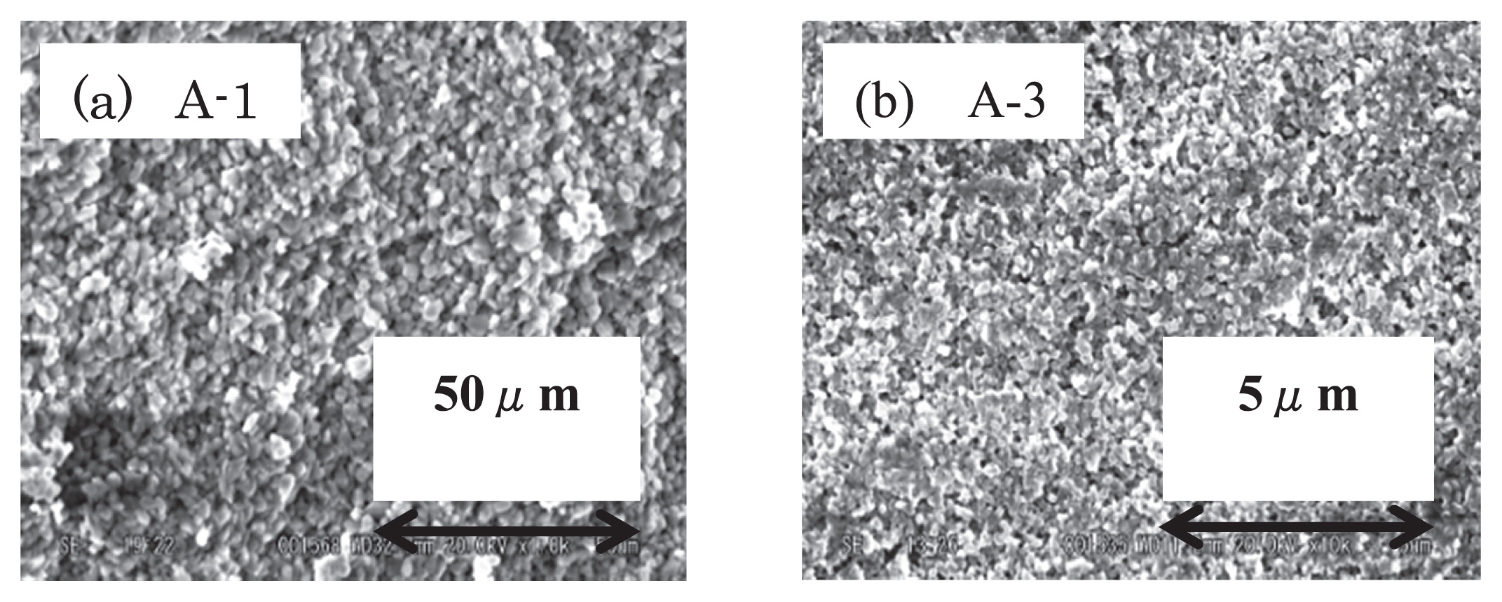
Fig. 4 presents the porosities of the alumina sintered matrices. There are no remarkable differences in porosity, despite variations in the grain size and sintering temperature. This unexpected result is verified by the SEM images shown in Fig. 5. This may be partly explained by noting that, although the two raw materials had very different nominal grains sizes, the actual primary particle sizes of the two powders were in fact almost the same. That is, the nominal 50 μm powder simply consisted of aggregates of smaller particles. Nonetheless, the SEM images do show that there may be some pore structure differences, and these differences were confirmed by subsequent studies, as described below.
3.2 Impregnation under centrifugal force
(a) Stainless matrix
Fig. 6 shows typical cross sections of capsules following impregnation trials at various centrifuge rotational speeds, using the S-2 matrix. One of the most remarkable aspects of this figure is the placement of the Sn-Bi alloy. That is, the alloy is found not only on the matrix but also under the matrix. This same phenomenon was observed for every specimen, and so it appears that the molten alloy is able to move through the slight gap between the matrix and the capsule, driven by the downward centrifugal force.
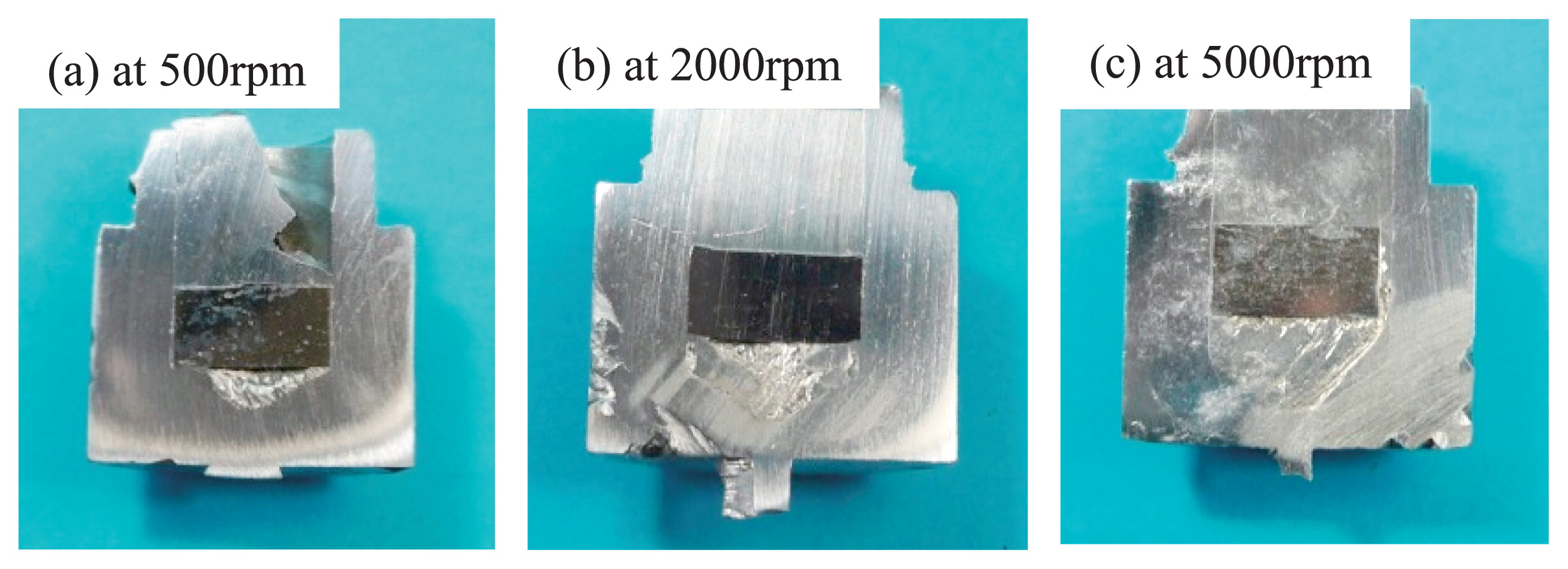
Fig. 7 presents typical SEM images of the base of the S-4 matrix, showing that the impregnation proceeds upwards, starting from the base. This peculiar bottom to top impregnation implies that the impregnation was driven not by the direct centrifugal force (which is oriented downward), but by the pressure applied to the molten alloy by the centrifugal acceleration. This pressure is essentially an isotropic force but becomes stronger in proportion to the depth, so that the strongest pressure emerges at the base of the specimen. With regard to the effect of the rotational speed, no impregnation is observed at 500 rpm, whereas shallow impregnation evidently begins at 2,000 rpm and the penetration becomes much deeper at 5,000 rpm.
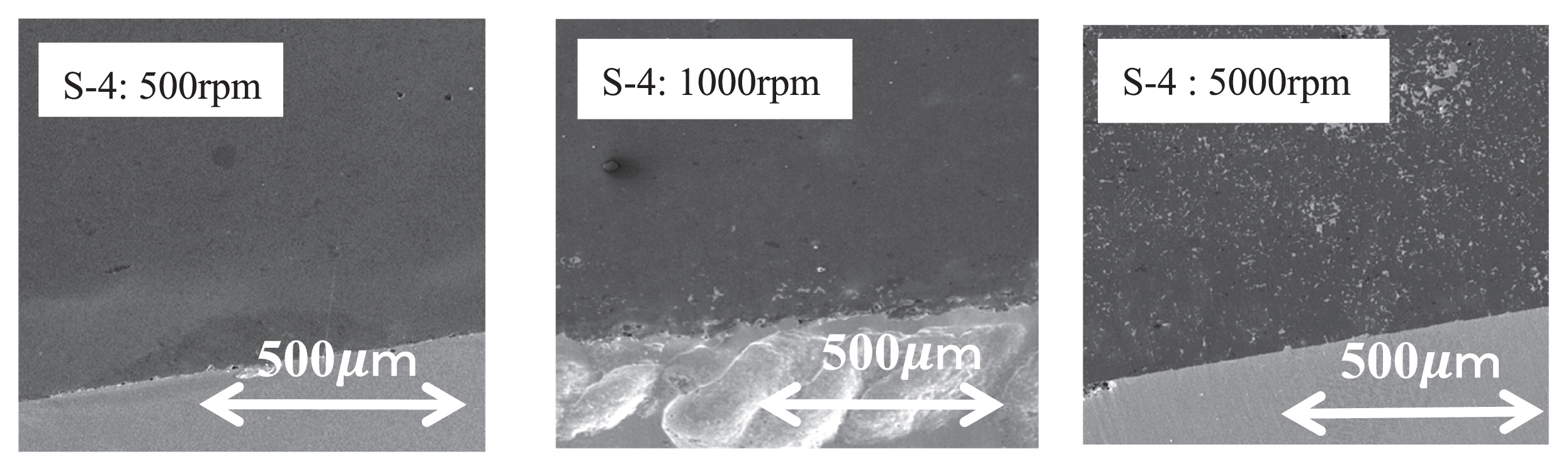
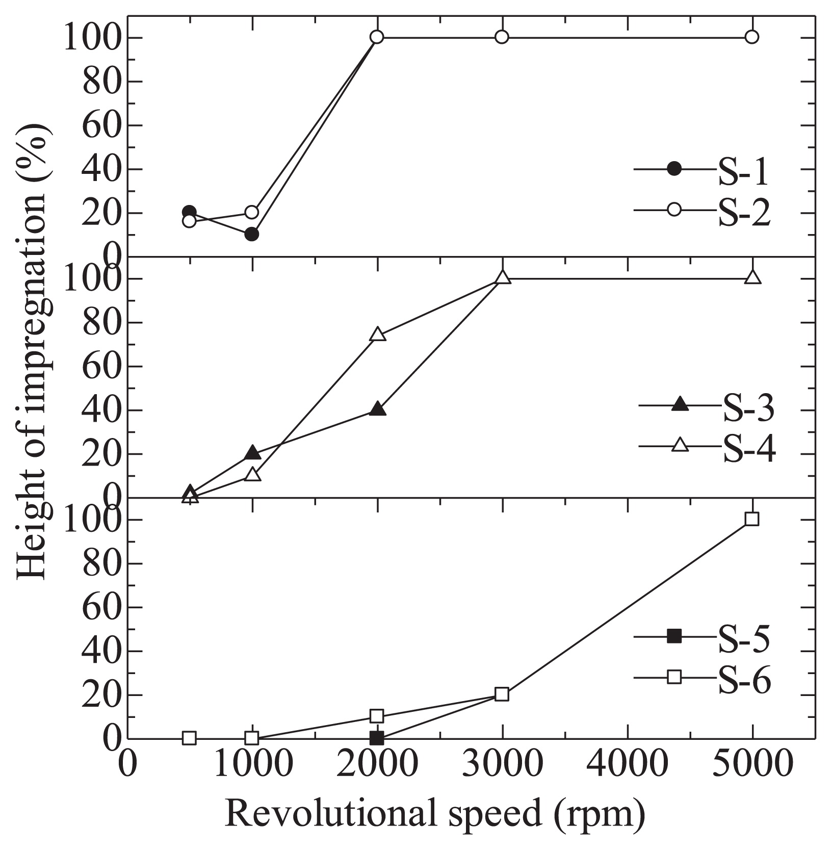
Fig. 8 summarizes the impregnation depths as functions of the rotational speed of the centrifuge for the S-1 to S-6 matrices. First, let us focus on the point at which the impregnation starts. Matrices with large pores (S-1, S-2) have a starting point at approximately 500 rpm, but this transitions to 1,000 rpm for the samples with moderately sized pores (S-3, S-4) and to 2,000 rpm or more for the small pore specimens (S-5, S-6).
It is also helpful to examine the height of the alloy infiltration. In the case of the large pore samples (S-1, S-2), full penetration is easily accomplished at 2,000 rpm, while 3000 rpm is required for the moderate pore sizes (S-3, S-4) and the smallest pore samples (S-5, S-6) need 5,000 rpm for complete alloy penetration.
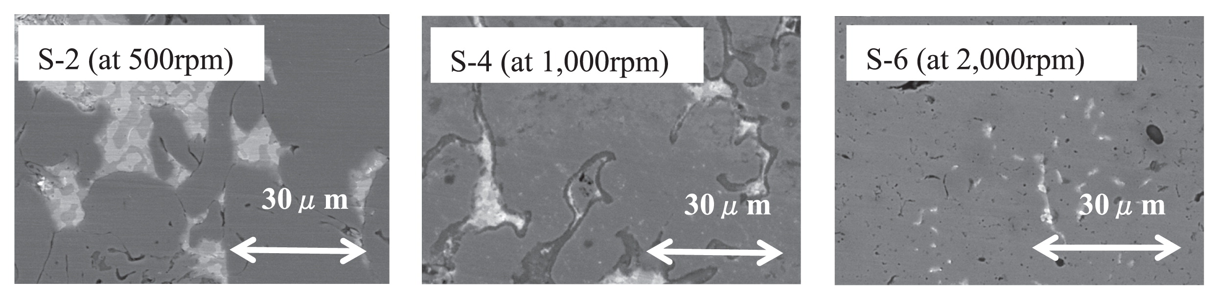
Fig. 9 presents observations of the molten metal front at the onset of impregnation in the S-2 (at 500 rpm), S-4 (at 1,000 rpm) and S-6 (at 2,000 rpm) matrices. These images show that the molten alloy can move into smaller pores at higher rotational speeds. Table 6 summarizes the smallest pore sizes that the molten metal will impregnate under each condition.
Table 5
Processing conditions during preparation of alumina matrices.
| Matrix |
Angle of contact [deg] |
| SUS316L |
120 |
| Alumina |
165 |
Table 6
Impregnation pore sizes.
| Sample No. |
S-1 |
S-2 |
S-3 |
S-4 |
S-5 |
S-6 |
A-1 |
A-2 |
| Pore size [μm] |
30 |
22 |
15 |
10 |
5 |
3 |
2 |
2 |
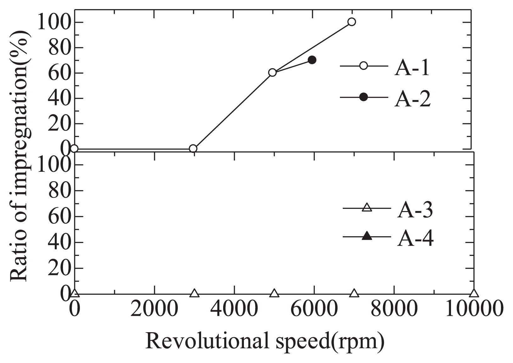
Fig. 10 provides cross sections of capsules following impregnation. Just as seen with the stainless steel matrices, the molten metal impregnates the alumina matrix from the base, moving upwards. In the case of the matrices made using the small grains (A-3, A-4), no impregnation is observed regardless of the experimental conditions, even when the maximum centrifugal force (10,000 rpm) is applied. In contrast, when using matrices made with larger grains (A-1, A-2), impregnation starts when a higher centrifugal force (5,000 rpm or more) is applied.
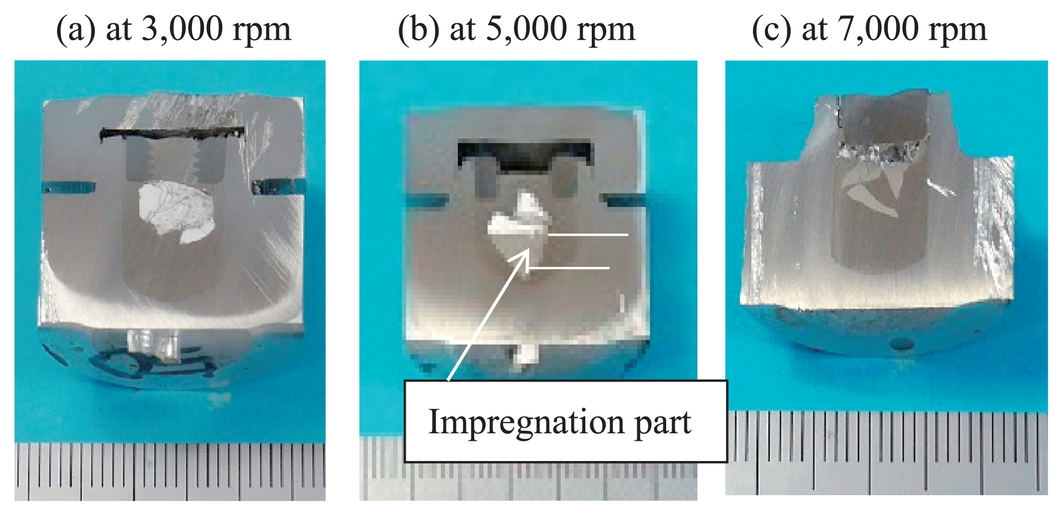
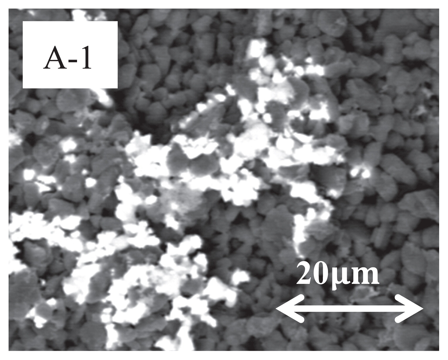
With regard to the impregnation heights of the A-1 and A-2 matrices, about half of the sample height is impregnated at 5,000 rpm, and full penetration occurs at 7,000 rpm and above (Fig. 11). Fig. 12 is an enlarged SEM image of the impregnation front observed in A-1 at 5,000 rpm. It shows that the molten alloy impregnates pores with a diameter of about 2 μm at 5,000 rpm. Another noteworthy result is that the alumina matrices exhibit a tendency to collapse at 7,000 rpm and above in the case of the A-1 samples, and at 5,000 rpm and above in the case of the A-2 specimens.
3.3 Discussion
To begin with, we can discuss the conditions at the onset of impregnation. In general, when the matrix is not readily wetted by the molten metal, or when the matrix has smaller pores, the impregnation of the molten metal into the matrix become difficult. It is well known that this phenomenon can be expressed by the Washburn equation, as below.
Here D is the pore diameter [m], γ is the surface energy of the molten metal [J/m2] (γSn = 0.56 J/m2), is the contact angle between the matrix and molten metal (see Table 5), and P is the pressure of the molten metal [Pa]. This equation indicates that a higher value of P is required under the more challenging penetration conditions described above. The question then becomes how best to estimate the actual P values under experimental conditions.
Figs. 6, 7 and 10 show that the impregnation starts not from the top but rather from the base of the matrix, indicating that the effective pressure, P, is equal to the pressure generated by the application of centrifugal force to the liquid metal. To verify this hypothesis, the pressure applied to the molten metal by centrifugal force was calculated with eq. (2), using an alloy density, ρSn, of 6.99 × 10³ kg/m3, a molten metal height in the capsule, h0, of 0.01 m and a rotor radius, r, of 0.11 m. The results of these calculations are presented in Fig. 13.
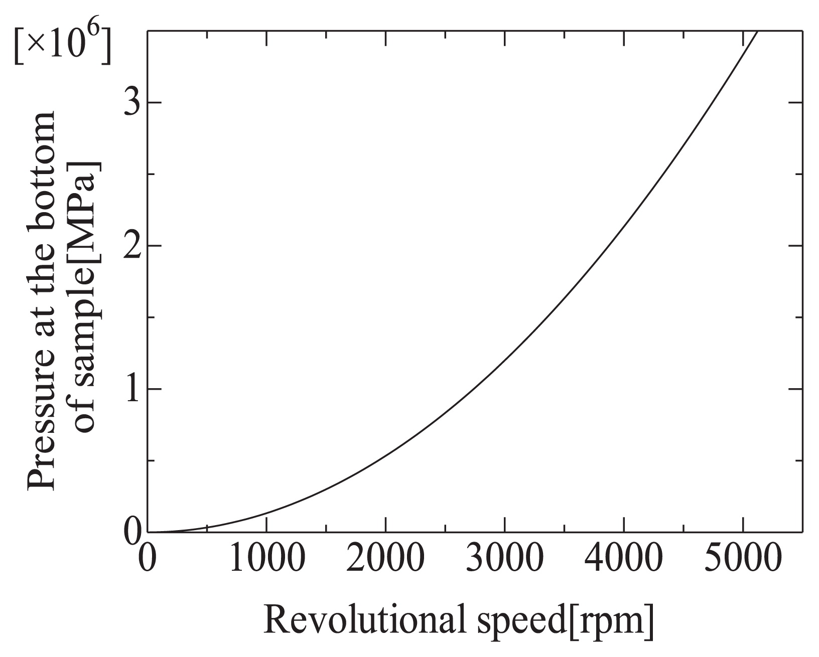
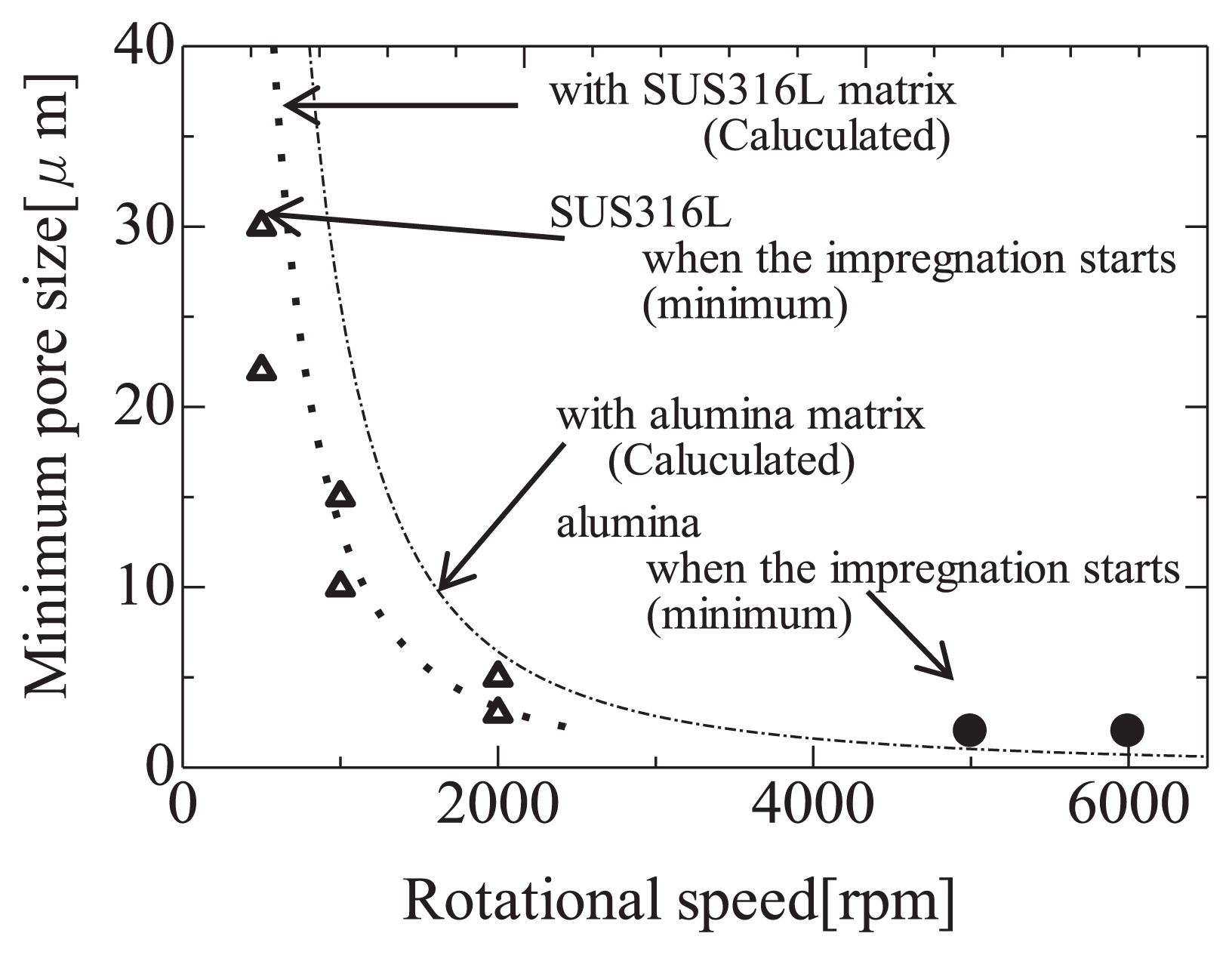
Combining eqs. (1) and (2), it is possible to estimate the minimum pore size at which the molten metal will be impregnated at each rotational speed. The estimated results show good agreement with the experimental values (Fig. 14). Therefore, the well-known Washburn equation is also applicable to impregnation phenomenon during centrifugal processing. It should be noted that the pressure generated in these trials was relatively low (up to several tens of MPa) because of the load limits of the capsule and rotor. In general, however, it is evident that the ability to impart significant centrifugal acceleration is essential to the impregnation of molten metals into small pores. Therefore, given a suitable level of rotational speed, this method has possibility for applications in the fabrication of new composite materials.
4 Conclusions
A high temperature centrifugal process was explored. This method consisted of combining a low Tm (411 K) Sn-Bi alloy with a P/M processed stainless steel or alumina matrix (poorly wetted by the alloy) in a capsule with subsequent heating to 673 K followed by centrifugation at rates up to 10,000 rpm. By this process, the molten alloy was forcibly impregnated into the pores of the matrices. The obtained results are as follows.
-
1)
After placing the heated capsule in the heat-insulating vessel, a centrifugal acceleration of 10,000 G (at 10,000 rpm) can be applied for a span of at least 1 ks prior to solidification of the molten alloy.
-
2)
Using this high temperature centrifugation process, the Sn-Bi alloy can be forcibly impregnated into stainless steel or alumina matrix pores. The minimum pore size into which the alloy can penetrate is increased with increasing centrifugal force. At the maximum centrifugal force, the alloy was impregnated into pores several microns in size.
-
3)
The force driving the impregnation is the pressure applied to the molten alloy by the centrifugal motion. The pore size that can be impregnated at a given centrifugal force, correlated to the pressure generated by that force, can be estimated using the Washburn equation.
References
- 1) L. L. Regal, W. R. Wilcox: “Materials Processing in High Gravity”, Proceedings of the Second Int. Workshop on Mater. Processing in High Gravity, in Potsdam New York, edt by L. L. Regal, W. R. Wilcox, Plenum Press, NY (1994).
- 2) L. L. Regal, W. R. Wilcox: “Centrifugal Materials Processing”, Proceedings of the Third Int. Workshop on Mater. Processing at high Gravity, in Potsdam New York, edt. L. L. Regal, W. R. Wilcox < Plenum Press, NY, (1997).
- 3) L. L. Regal, W. R. Wilcox: “Processing by Centrifugation”, Proceedings of the Fourth Int. Workshop on Mater. Processing at High Gravity, in Potsdam New York, edt. L. L. Regal, W. R. Wilcox, Kluwer Academic / Plenum Publishers, NY, (2001).
- 4) F. F. Lange: “Powder Processing Science and Technology for Increased Reliability”, J. AM. Ceram. Soc., 72[1] (1989) 3–15.
- 5) T. Kimura, S. Sakaguchi, M. Nakamura: “The Correlation Between the Casting Behaviour and the Particle Aggregated Structure of Fine Ceramics in a Concentrated Slurry”, J. Soc. Powder Technol., Japan, 33 (1996) 371–378.
- 6) E. Beylier, R. L. Pober, M. J. Cima: “Centrifugal Casting of Ceramic Components”, Ceramic Transactions, Vol. 12, Ceramic Powder Science. Edited by G. h. Messing, S. Hirano, and H. Hausner American Ceramic Society, OH. (1990) 529–536.
- 7) H. Y. Suzuki, K. Shinozaki, S. Tashima, H. Kuroki: “Development of Alumina by High-speed Centrifugal Compaction Process and Analysis on Improved Mechanical Properties of This Alumina”, J. Jpn. Soc. Powder Powder Metallurgy, 51 (2004) 423–434.
- 8) H. Y. Suzuki, H. Kuroki: “Net Shape Formation of Sub-micron Alumina with Reduced Flaws by High-speed Centrifugal Compaction Process”, Metals and Mater. Int., 10 (2004) 185–191.
- 9) Y. Kinemuchi, K. Watari: “Thick Film Processing via Centrifugal Sintering”, J. Jpn. Soc. Powder Powder Metallurgy, 55 (2008) 163–169.
- 10) Y. Kinemuchi, K. Tazoe, K. Nakamura, K. Watari, H. Morimitsu,, H. Ishiguro, S. Uchimura: “Diffusion Bonding Assisted by Centrifugal Force”, J. Ceram. Soc. Jpn., 111 (2003) 733–737.