Crack detection on interior walls of buildings using UGV-captured images
2023 Volume 4 Issue 2 Pages 7-14
Details
2023 Volume 4 Issue 2 Pages 7-14
In this research, the proposed method for automatic detection of cracks in interior wall surfaces using an unmanned ground vehicle (UGV) is presented. The method consists of three main steps: (1) acquiring interior wall surface images using an autonomous UGV, (2) generating orthoimages to capture an overall view of the inspection area, and (3) detecting crack locations using the YOLO-v7 model. For creating the orthoimages used by Structure from Motion (SfM), an indoor navigation algorithm combining AR markers and LiDAR data is proposed. The algorithm detects AR markers using OpenCV and uses LiDAR to measure the distance and angle between the UGV and the wall. The UGV is guided to maintain a constant distance and align parallel to the wall. Experimental verification is conducted on mortar-finished interior wall surfaces in a building, demonstrating the effectiveness of the proposed method. The UGV captures images while in motion, creating orthoimages and detecting cracks using YOLO-v7. The results show that orthoimages allow for the detection of significant cracks, but direct utilization of UGV-captured images is necessary to detect all cracks. The proposed method offers a convenient way to acquire wall surface images and enables automatic crack detection using orthoimages and YOLO-v7. The navigation algorithm facilitates UGV traversal at a constant distance from the wall. Overall, the research presented the potential of using UGVs for automatic crack detection from images of indoor building environments.
In recent years, the utilization of robotics technologies such as Unmanned Air Vehicles (UAVs) and Unmanned Ground Vehicles (UGVs) has rapidly advanced in the architecture and civil engineering field, finding applications in construction sites, surveying, visual inspections, and more1-3). Specifically, UAVs have been actively employed combining with deep learning techniques, Mask R-CNN4), SSD 5), and YOLO 6, 7), to detect and assess damages such as cracks, corrosion, and delamination in infrastructures like bridges and dam embankments8-13). Due to the requirement of periodic inspections every five years for bridges in Japan14), recently, UAVs are being used to simplify visual inspections. UGVs are commonly used for material transport and layout marking in construction3) and have been increasingly applied to indoor environment measurements in response to the COVID-19 pandemic. However, compared to infrastructures, the utilization of UAVs in building environments faces additional constraints and regulations due to factors such as indoor settings and dense urban areas, resulting in limited practical examples. Furthermore, the utilization of UAVs or UGVs for visual inspections in indoor building environments is still relatively uncommon15-17). On the other hand, the Ministry of Education, Culture, Sports, Science and Technology has provided the " Guidebook for earthquake protection for nonstructural members of school facilities18)", which recommends regular visual inspections of nonstructural elements such as external walls, internal walls, and ceilings to enhance the safety of school facilities. Typically, these recommended visual inspections rely on human observers, including teachers, leading to potential inconsistencies in the quality of inspections.
This research aims to propose a damage inspection method to target cracks in interior walls and ceiling surfaces of buildings, particularly those affected by aging or small-to-medium earthquakes. An automatic crack detection method for surfaces of interior walls is proposed using the UGV. The detection of crack locations in the interior wall surfaces is accomplished by autonomously maneuvering the UGV while capturing and collecting images of the wall surfaces, followed by automatic crack detection using the YOLO-v76,7), which is a widely used deep learning approach. Additionally, combining LiDAR and AR markers19), an indoor navigation algorithm is also proposed, which allows the UGV to autonomously travel at a consistent distance from the walls. The effectiveness of the proposed crack detection method for interior wall surfaces using the UGV is evaluated through a validation experiment on mortar-finished wall surfaces of buildings.
The proposed crack detection method for the interior wall surfaces involves three main steps: (1) acquisition of the interior wall surface images using an autonomous UGV, (2) generation of orthoimages representing the entire inspection area, and (3) detection of crack locations on the interior wall surface using YOLO-v7. The process involves capturing images of interior wall surfaces, creating orthoimages, and automatically detecting crack locations. The orthoimages of the interior wall surfaces are created with the purpose of capturing the overall view and overview of the targeted inspection areas. The creation of wall surface orthoimages involves the use of Structure from Motion (SfM) technique, ensuring that approximately 80% overlap is maintained among the captured images to generate the orthoimage. Additionally, it is necessary to maintain a constant distance between the UGV and the interior wall during the image capture process.
For training a YOLO-v7 model to detect the cracks in the interior wall surfaces, a dataset of crack images is necessary. However, due to privacy concerns, the dataset is not readily available. On the other hand, in Japan, most infrastructure are publicly managed by national or local governments. A large number of crack images of infrastructure are widely available and publicly accessible. Therefore, in this research, a substitute dataset of concrete cracks from bridges are used as the training dataset. The data augmentation of YOLO-v7 includes the random application of up-and-down flipping, left-right flipping, transparent composition, mosaicking and HSV augmentation. The images for training the YOLO-v7 model are annotated with polygons using VGG-Image-Annotator. Bounding boxes obtained by scanning the boundaries of the polygons are used as label information. The dataset used in this research was created for bridge damage detection and includes data on corrosion, crack, free lime, leaking, and spalling. Fig.1 shows the details of the training dataset for YOLO-v7. A total of 3,756 damage images were obtained from bridge inspection surveys. 80% of these images were used for training, 10% for validation, and 10% for testing. Image recognition accuracy validation resulted in a Precision (P) of 0.523, Recall(R) of 0.490, and mAP_0.5 of 0.486 across the five types of damages. For the crack only, P is 0.479, R is 0.583, and mAP_0.5 is 0.482.

When capturing the interior wall surfaces using Structure-from-Motion (SfM) to create orthoimages, it is necessary to maintain a certain distance from the wall and allow the UGV to travel along the interior wall. In this research, an indoor navigation algorithm that combines AR markers and LiDAR data, which enables autonomous UGV travel along the wall without requiring tedious pre-preparation20). Fig. 2 illustrates the proposed indoor navigation algorithm. And Fig.3 shows the instructions given to the UGV using AR makers.


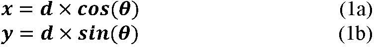
In the proposed indoor navigation algorithm, OpenCV21, 22) is utilized for detecting AR markers and extracting the wall line. For AR makers, the web camera equipped on the UGV is utilized to detect and identify the AR makers on the traveling path. When the size of the AR maker image exceeds the predetermined threshold size, instruction such as turning right, turning left, or stopping are given to the UGV. And AR markers are not utilized for photography instructions. In UGV travel along the wall, LiDAR is used to measure the distance and angle between the UGV and the wall. The UGV is autonomously guided to maintain a parallel and constant distance from the wall. Firstly, the LiDAR data is converted from polar coordinates (d, θ) to Cartesian coordinates (x, y) based on the scanning angle of the LiDAR and the distance to the wall, as shown in equation (1a) and (1b):
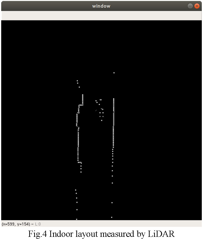
in which d represents the distance to the wall measured by LiDAR, and θ represents the scanning angle of LiDAR. Using the point cloud data from LiDAR, an indoor layout diagram is created. Next, the created indoor layout diagram is subjected to edge extraction using the Canny algorithm and converted into a binary image. The resulting binary image is then further processed using the Hough transform to detect the wall lines. As an example, Fig.4 shows the layout diagram created using the point cloud, while Fig.5 illustrates the extracted wall lines on the right side of the hallway. In Fig.5, the extracted wall lines on the right side is indicated by a blue line. Here, the coordinates (x1, y1) and (x2, y2) of the upper and lower ends of the wall line are used to calculate the angle of the UGV with respect to the wall using equation (2).

The distance L (pixels) between the UGV and one side of the wall within the image can be determined using equation (3):

In which 𝑤𝑚 represents the distance (m) from the wall measured by LiDAR, 𝑓𝑚 represents the LiDAR measurement radius (m), and 𝑓𝑝 denoted the width of the image in pixels. By employing the posture control based on equations (2) and (3), the UGV is able to autonomously navigate while maintain a constant distance from the wall and aligning itself parallel to the wall.
The purpose of conducting the experimental verification is to evaluate the effectiveness of the proposed automatic crack detection method for interior wall surfaces using the UGV. The experimental verification was conducted on the mortar-finished wall surfaces inside the university building, as shown in Fig. 6 (left wall). The UGV, equipped with a GoPro Hero4 Session, is depicted in Fig. 7. The utilized UGV employs mecanum wheels, enabling movement in all directions. YOLO-v7 is deployed on Google Colaboratory, utilizing Tesla A100 as the GPU. The pre-training of YOLO-v7 was performed with the settings shown in Table 1, using a dataset of 803 images of concrete cracks of bridges.
In the experimental verification, indoor navigation using the proposed LiDAR and AR markers is employed to guide the UGV while capturing images of the mortar-finished wall surfaces. While the UGV was in motion, the mortar-finished interior wall surface images are captured using a GoPro HERO4 Session at a rate of one image per second to create orthoimages of the wall surface, ensuring approximately 80% overlap among each captured image. In this experiment, the capture interval was determined through trial and error. And it is also necessary to maintain a constant distance between the UGV and the wall surface for creating the orthoimage. The camera settings for the GoPro HERO4 Session are presented in Table 2.
To capture an overview of the entire targeted wall surface, 155 wall surface images of size 3264×2448 pixels were captured. These images were then utilized to create orthoimages of the wall surface using Metashape Pro23), which is one of SfM software. The resulting orthoimage of the wall surface is depicted in Fig.8. From Fig.8, it can be observed that although the glass window area is not accurately reproduced in the orthoimage, the wall surface areas with cracks are largely represented with accuracy. However, since the entire targeted wall surface is reproduced in the orthoimage, the image size becomes large, measuring 26240×2560 pixels. And the resolution of the orthoimage is 0.6 mm/pixel.
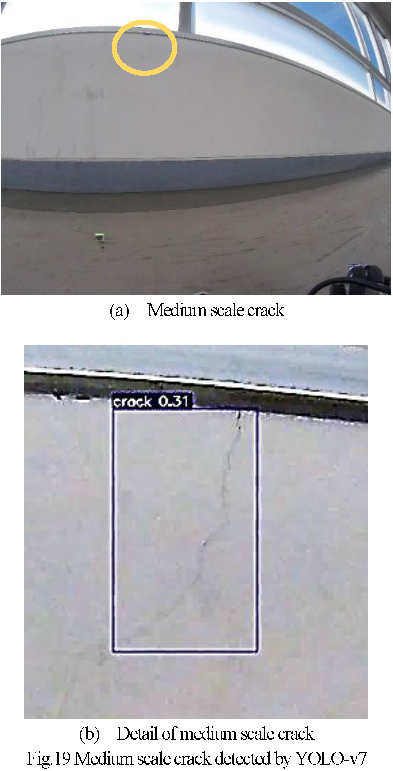
Next, based on the orthoimages, an attempt is made to automatically detect the cracks on the mortar-finished wall surface using YOLO-v7. The orthoimages are divided into164 images of size 640×640 pixels to match the model requirements of YOLO-v7. Crack detection is then carried out using YOLO-v7 implemented on Google Colaboratory. Futhermore, YOLO-v7 takes 16.87 ms to process the crack detection of a single image sized 640x640. The recomposited images showing the detected cracks using YOLO-v7 are shown in Fig.9 to 16. The yellow circles shown in Fig.9 to 16 indicate the cracks detected by YOLO-v7. On the other hand, the red rectangles represent the cracks that were not detected. The reason for the undetected cracks can be attributed to the orthoimages created using SfM, where the cracks may not be clear or distinct enough to be detected. In addition, several cracks present in the images captured by UGV disappear or become unclear during the process of creatingthe orthoimage, rendering them unrecognizable in the orthoimage. From these results, it can be observed that using orthoimages for crack detection allows for the detection of significant cracks, which width are 0.4mm or more, on the wall surfaces. However, due to resolution, it is insufficient to detect all cracks. Therefore, an attempt was made to directly apply YOLO-v7 to the images captured by UGV in order to detect all cracks. While using the captured images directly might be affected by lens distortion, capturing with approximately 80% overlap allows for the utilization of central image portions with minimal distortion from the lens. Therefore, no consideration has been given to lens distortion in this experiment. Examples of the results obtained by directly using images captured by the UGV for crack detection are shown in Fig.17 to 20. The cracks that are not detected, indicated by red rectangles within the orthoimages, are illustrated in Fig.17 (a) for Fig.11 and Fig.17 (b) for Fig.12. From Fig.17 to 20, it can be observed that by directly utilizing images captured by the UGV, cracks on the interior wall surfaces, including those not detected in the orthoimages, can be reliably detected. Furthermore, as observed in some images, there are cases where cracks are overlooked, as shown by the yellow circle in Fig.18(a). However, in different images where overlapping coverage occurs, as shown by the yellow circle in Fig. 18(b), the cracks are detected, and there are few instances of missed cracks. Additionally, as demonstrated in Fig.19 and Fig.20, it has been confirmed that even moderately blurred cracks can be detected. From these results, using captured images directly, YOLO-v7 could detect about 50 % of the cracks on the wall. However, cracks with a width of 0.2mm or more were almost entirely detectable.
Based on the above results, it has been confirmed that the proposed navigation algorithm allows for convenient acquisition of interior wall surfaces images suitable for orthoimage generation using SfM with the UGV. Furthermore, it has been demonstrated that the SfM-generated orthoimages provide an overview of the target area, and the YOLO-v7 algorithm can automatically detect crack locations. However, it should be noted that for detecting cracks on interior wall surfaces, the resolution of the orthoimages is insufficient, and it has been verified that direct utilization of images captured by the UGV is necessary.


In this research, an automatic crack detection method for concrete and mortar-finished wall surfaces in indoor building environments was proposed using a UGV. Additionally, a convenient indoor navigation algorithm that combines LiDAR and AR markers, allowing for automated traversal at a consistent distance from the wall surface, was proposed for the purpose of generating orthoimages using SfM. The proposed automatic crack detection of interior wall surfaces utilizes the images captured by the UGV to create orthoimages representing the entire inspection area, and employs YOLO-v7 to detect crack locations using the captured images. The proposed convenient indoor navigation algorithm utilizes AR markers to provide instructions to the UGV, while LiDAR detects the lines on the wall surface, enabling autonomous UGV traversal at a constant and parallel distance from the interior wall surface.
The utility of the proposed method was verified through the experiment targeting mortar-finished interior wall surfaces. The results confirm that the UGV is capable of autonomous traversal along the interior wall surface, maintaining a constant distance, to capture photographs suitable for SfM. Furthermore, it has been demonstrated that the SfM-generated orthoimage provides an overview of the inspection area, and the YOLO-v7 algorithm enables automatic detection of crack locations. Additionally, it is better to use the images of the wall surface captured by the UGV directly for crack detection using YOLO-v7, rather than orthoimages.