Integrated 360-Degree Visualization and Damage Detection System for Infrastructure Inspection: A Storm Drain Case Study
2025 Volume 6 Issue 2 Pages 1-12
Details
2025 Volume 6 Issue 2 Pages 1-12
The deterioration of underground storm drain infrastructure represents a significant challenge for urban asset management, with failures often remaining undetected until catastrophic events occur. This paper presents a novel inspection information management system that leverages 360-degree panoramic imaging and automated damage detection to enhance the efficiency and comprehensiveness of storm drain condition assessment. The proposed system employs commercially available 360-degree cameras mounted on robotic platforms to capture equirectangular panoramic images of drain interiors, which are then processed through a specialized framework. This framework converts equirectangular images to cubemap representations to address spherical distortion challenges, applies semantic segmentation for automated corrosion detection, and reconstructs processed cubemaps into panoramic visualizations with damage overlay information. The system integrates Structure from Motion (SfM) techniques to establish spatial relationships between multiple camera positions, enabling intuitive navigation through the storm drain network while maintaining viewing context. For damage detection, we implement a modified Segment Anything Model (SAM) with Low-Rank Adaptation (LoRA) fine-tuning, specifically optimized for corrosion identification in storm drain environments. Field implementation demonstrates the system’s effectiveness in detecting and visualizing corrosion damage while minimizing false positives through selective face processing. The developed system operates in both cloud-based and local environments, providing flexible deployment options while maintaining consistent functionality. By enabling comprehensive visual documentation, efficient navigation, automated damage detection, and systematic recording of inspection information, this system contributes to the development of digital twins for underground infrastructure management and supports more effective maintenance planning.
The aging of infrastructure has become a critical issue in many developed countries, particularly in nations like Japan where a significant portion of civil infrastructure was rapidly constructed during the economic boom period 1). While attention has often focused on visible structures such as bridges and highways, underground infrastructure - especially storm drainage systems - faces equally serious deterioration issues that remain largely hidden from public view until catastrophic failures occur 2)-4).
A recent incident in January 2025 highlighted this problem when a major road collapse in an urban area of Japan was directly attributed to undetected damage in an aging storm drain pipe 5). This event underscores the urgent need for efficient inspection and maintenance systems for underground drainage infrastructure. The challenge is particularly daunting given the vast networks of storm drains that extend beneath urban areas, making manual inspection of each pipe section both time-consuming and cost- prohibitive 6).
In recent years, digital twin technology has emerged as a promising approach for infrastructure management. A digital twin is a virtual representation of physical assets that can be used for various purposes including monitoring, analysis, and simulation 7)-14). For underground infrastructure like storm drains, creating and maintaining accurate digital twins presents unique challenges due to limited accessibility and the difficulty of obtaining comprehensive visual data. To address these challenges, various innovative data acquisition technologies are being utilized for efficient maintenance management, including Unmanned Aerial Vehicles (UAV) 15)-17), Light Detection and Ranging (LiDAR) systems for point cloud data collection 18)-20), and 360-degree omnidirectional cameras 21), 22). These technologies enable more comprehensive assessment of infrastructure conditions, particularly in difficult-to-access environments, thereby enhancing the development and utility of digital twin applications.
Traditional storm drain inspection typically relies on closed-circuit television (CCTV) cameras that provide limited field-of-view images, making it difficult to obtain complete visual information of pipe conditions in an efficient manner 23). Additionally, conventional viewers used to display these images are generally limited to basic display functionality, lacking capabilities for systematically recording and managing inspection data such as damage locations, damage types, and temporal changes.
To address these challenges, this study proposes a novel inspection information management system that utilizes 360-degree cameras mounted on robotic platforms to capture spherical images of storm drain interiors. By employing Structure from Motion (SfM) techniques to link multiple spherical images based on their capture positions, the system enables seamless viewing of drain conditions from various positions while maintaining spatial context. Furthermore, the system incorporates semantic segmentation to automatically detect corrosion and other damage types, with results projected back onto the original spherical images for intuitive visualization.
The proposed system offers several key advantages: (1) comprehensive visual documentation of storm drain conditions using commercially available 360-degree cameras; (2) efficient navigation through multiple images with maintained spatial relationships; (3) automated detection of damage through semantic segmentation; (4) systematic recording of damage information including location, type, and severity; and (5) integration of this information into a unified management system that contributes to the digital twin of the drainage infrastructure.
This paper details the development of this system and its application to actual storm drain inspection scenarios. The system is designed to function in both cloud-based and local environments, allowing administrators to adapt its use according to their specific requirements and constraints. By enabling more efficient and comprehensive storm drain inspection, this system aims to contribute to the prevention of infrastructure failures and the optimization of maintenance resources.
This paper is based on and extends the work of Yamane et al. 24), translating the original concepts into a broader infrastructure inspection context while expanding the technical framework with additional functionalities for automated damage detection and comprehensive visualization.
(1) Primary Functions
The main features of the inspection information management system developed in this research are presented in Fig. 1. As shown in Fig. 1(a), similar to conventional spherical image viewers, this system can display 360-degree camera images captured by commercially available devices deployed within storm drain pipes. Users can drag across the image to view captured content in any direction on the screen. Additionally, the upper left corner of the system interface simultaneously displays the capture position of the currently displayed image within the overall map and the viewing direction.
Furthermore, as illustrated in Fig. 1(a) and (b), the system displays icons representing other camera capture coordinates on the currently viewed image. Users can click on these icons to navigate to images captured from those camera positions. For example, Fig. 1(b) shows the image displayed after clicking an icon in the screen shown in Fig. 1(a). To facilitate intuitive understanding of the three-dimensional spatial relationships between camera positions, these icons are automatically adjusted in opacity and size according to their distance from the currently displayed image’s capture position. Additionally, the icons are color-coded based on their position within the storm drain pipe structure - different colors indicate whether the camera is positioned in the upper or lower sections of the drain. Users can also navigate between camera positions by clicking on camera coordinates displayed in the map in the upper left corner of the system interface. During camera position transitions, the system calculates the destination viewpoint direction based on the viewpoint direction displayed on the screen before movement, enabling seamless navigation without resetting the viewing direction when switching between images. This functionality allows for rapid display of images from any capture position, even when dealing with a large number of images.
As shown in Fig. 1(c), the system allows users to designate areas of damage or defects and attach annotation data representing damage attributes. Users can define target regions as polygons and add information such as damage type and severity ranking to these regions. In addition, users can upload enlarged images of damaged areas or photographs from angles that are difficult to capture with 360- degree cameras. The metadata of damage information configured here is also reflected in the damage information list shown in Fig. 1(d). Users can select damages from this list to navigate directly to the images capturing those damages.
Fig. 1(e) demonstrates the damage location and type search functionality, which enables users to filter and locate specific types of deterioration within the storm drain system. This feature is particularly valuable for maintenance planning and prioritization, as it allows quick identification of similar damage patterns across the drainage network.
The system also includes a GIS (Geographic Information System) capability as shown in Fig. 1(f), which displays the locations of inspected storm drains on a map interface. By selecting the pins representing storm drain coordinates on the map, users can launch the viewer screen displaying images of that drainage structure. When selecting each structure’s pin, the structure’s name and capture date are displayed, allowing users to select the desired inspection date to view the corresponding data. On this screen, pins are color-coded according to structural integrity ratings (I-IV), and users can filter to display only structures with specified integrity ratings. Users can also access a list of storm drains directly from this screen, which can be sorted by structure ID, integrity rating, or name for efficient access.
Through implementing this spherical image viewer specialized for storm drain infrastructure maintenance, we have constructed a system capable of centralized management of inspection information. While this paper describes various mathematical processes, it should be emphasized that these calculations are executed in the background of the system, ensuring a user-friendly experience without requiring users to understand the underlying computational methods.

(2) Camera position information linking
In this system, it is essential to derive spatial relationships between multiple cameras used during inspection and represent them as interconnected data within the storm drain network. To accomplish this position correlation, we employed Structure from Motion (SfM), a technique that identifies external parameter matrices representing camera poses from multiple images.
Fig. 2 Visualization of the Structure from Motion (SFM) reconstruction process. The standard perspective shows the reconstructed 3D point cloud (colored by height) surrounded by camera positions (red markers) with their viewing directions (red lines). The green dashed line represents the camera trajectory during data acquisition.
Fig. 3 illustrates the feature matching process between equirectangular images using SfM. The colored lines (red and blue) represent the matched feature points between panoramic images captured at different positions within the storm drain. This feature matching is the fundamental mechanism of SfM, where distinctive visual elements are identified across multiple images despite the challenging low- texture environment typical of concrete storm drains. The algorithm extracts robust features using SIFT (Scale-Invariant Feature Transform) descriptors, which are invariant to changes in scale, rotation, and illumination-particularly valuable for the variable lighting conditions encountered in underground infrastructure inspection.
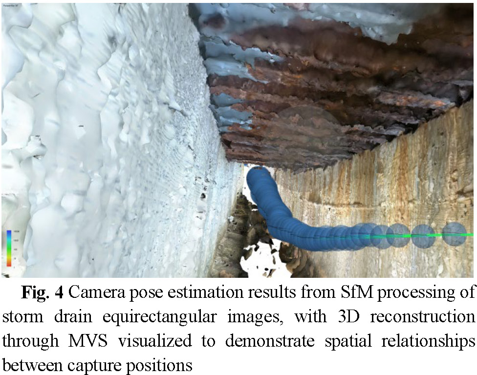
Fig. 4 illustrates the results of Structure from Motion (SfM) applied to equirectangular images, successfully identifying spherical image capture coordinates within the storm drain environment. The 3D reconstruction shown was generated through Multi-View Stereo (MVS) processing to clearly visualize camera positions and their spatial relationships. While SfM is often followed by MVS or Neural Radiance Fields (NeRF) processing to obtain high-precision 3D data of target structures- processes that typically require numerous images and extensive computation time 25), 26), this system primarily utilizes SfM for camera pose identification only. This approach requires fewer images and eliminates the need for time-intensive post- processing, as the system’s main purpose is to display the actual images in a viewer rather than create high- precision 3D reconstructions. Nevertheless, the camera poses identified are sufficiently accurate to enable 3D reconstruction through MVS if desired, demonstrating adequate precision for navigating between images in the viewing interface.
The external parameter matrices calculated for each camera are exported in XML format as shown in Fig. 5. As illustrated, the external parameter matrix for equirectangular images is defined similarly to those from standard monocular cameras. In this definition, the center of the equirectangular image represents the front direction vector, and the upper edge represents the upward direction vector. Our system loads these XML files to establish positional relationships between cameras. The transformation matrix includes rotation and translation components that define each camera’s position and orientation within a global coordinate system, while the covariance matrices provide statistical information about the estimation precision.
Furthermore, when switching between camera positions within the viewer, the system maintains consistent viewing direction by calculating rotation angles based on the line-of-sight vector, as shown in Fig. 6. This calculation uses the angle between the front direction vector Z₁ obtained from the external parameter matrix and the line-of-sight vector to determine the rotation angle from the front direction vector Z₂ of the destination camera. By implementing this mechanism, the system ensures seamless screen transitions with preserved viewing direction, enhancing the user experience by providing intuitive navigation through the storm drain inspection data.
Currently, the system relies on manual on-screen operations for designating damaged areas and assigning metadata. While the current functionality is sufficiently practical for storm drain inspection applications, further automation could be achieved by integrating damage detection models that we have developed 27)-30). These models could automatically identify and classify common storm drain defects such as corrosion, cracks, infiltration, and sediment accumulation, thereby reducing the burden on inspectors and improving the efficiency of the inspection process.


(3) Operating Environment
The architecture of this system is designed to provide equivalent functionality in both cloud and local environments, enabling flexible operational configurations based on the implementing organization’s requirements.
When utilizing cloud resources, users can access the system regardless of location or device. This approach is suitable for remote work environments and multi-site operations, intended to facilitate efficient task execution while reducing operational management burden.
Conversely, considering scenarios where cloud operations may be restricted due to inspection data confidentiality or organizational security policies, the system also supports operation in local environments without network connectivity.
For the cloud implementation of this system, we employed Amazon Web Services (AWS) Elastic Compute Cloud (EC2). Specifically, t2.micro instances (1 vCPU, 1GB RAM) were selected, considering cost efficiency and operational practicality. The system adopts a lightweight design specialized for displaying spherical images and managing inspection data, achieving stable performance even with relatively modest computing resources. In constructing the server environment, we implemented a web application server using the Express.js framework based on the Node.js runtime environment 31). The system’s core functionalities, including spherical image display and annotation information management, are designed on the premise of asynchronous processing, enabling efficient operation even under limited resources. Furthermore, to ensure continuous system operation, we incorporated PM2 32), a Node.js process manager, implementing automatic restart capabilities during unexpected system failures and log management functions to achieve stable system operation.
For efficient management of storm drain inspection data, we adopted a distributed storage architecture. While the system’s application code and related resources are stored in AWS Simple Storage Service (S3), the voluminous spherical image data for storm drain inspection is distributed across individual storage servers designated by administrators, considering cost efficiency and data security. Through this design, access to image data is implemented via URL links within the application, allowing users to seamlessly view data without awareness of its physical location. Additionally, this distributed architecture enables efficient management of inspection data while allowing flexible data placement according to administrative requirements.
Regarding security aspects, we implemented network access control using AWS Security Groups. For external access, only HTTPS protocol (port 443) and SSH connections (port 22) are permitted. While the system internally operates on port 8000, we adopted a configuration that securely routes external access from port 443 to internal port 8000 via AWS Application Load Balancer (ALB). All other ports are closed to minimize unauthorized access risks. Furthermore, communication encryption is achieved utilizing AWS Certificate Manager (ACM).
Moreover, in the system design, we incorporated microservice architecture concepts to ensure loose coupling between components such as image display functionality and annotation management. This approach facilitates future functional enhancements, particularly integration with object detection models under development, while improving maintainability.
The proposed framework employs a novel approach to detecting corrosion in storm drain infrastructure using spherical panoramic images. As illustrated in Fig. 7, the methodology consists of four principal stages. Initially, the input equirectangular panoramic image is transformed into a cubemap representation, which effectively addresses the distortion challenges inherent in spherical imagery. This conversion facilitates more accurate processing by decomposing the 360-degree view into six individual faces representing different directional perspectives.
In the second stage, semantic segmentation is applied to the cubemap faces, with particular focus on those most likely to contain critical infrastructure elements (left, right, and top faces). This selective processing strategy optimizes computational efficiency while maintaining detection accuracy. The segmentation model identifies potential corrosion regions and generates corresponding binary masks.
The third stage involves recombining the processed cubemap faces, including detected damage regions, into a reconstructed panoramic view. This transformation preserves all detection results while restoring the comprehensive 360-degree perspective necessary for context-aware inspection assessment.
Finally, the system integrates the processed panoramic images into a 360-degree visualization interface with linked JSON metadata. This metadata contains structured information about detected damage, including precise location coordinates, bounding box dimensions, and classification attributes. This integrated approach enables inspectors to efficiently navigate, document, and evaluate storm drain conditions through an intuitive visualization system.

(1) Semantic segmentation model
For corrosion detection in storm drain infrastructure, we implemented a modified Segment Anything Model (SAM) 33) architecture with Low- Rank Adaptation (LoRA) 34) fine-tuning. The base SAM model, originally developed as a foundation model for general segmentation tasks, provides robust capabilities for identifying complex visual patterns through its vision transformer backbone (ViT-B). To adapt this general-purpose model to the specific requirements of storm drain corrosion detection, we employed LoRA, a parameter-efficient fine-tuning technique that significantly reduces the number of trainable parameters while maintaining model performance.
The LoRA implementation introduces rank-512 adaptation matrices into the attention layers of the SAM model, enabling targeted modification of the feature representation relevant to corrosion characteristics while preserving the model’s general segmentation capabilities. This approach is particularly advantageous for specialized domains like infrastructure inspection, where labeled training data may be limited but high precision is required.
Model training and evaluation were conducted on a Windows-based workstation equipped with an AMD Ryzen 9 9950X processor, 128GB RAM, and an NVIDIA GeForce RTX 4090 GPU.
(2) Training dataset
The model was fine-tuned using a composite dataset comprising two publicly available corrosion datasets: the Corrosion Classification Dataset (Bianchi et al.)35) and the University of Maine Corrosion Image Collection 36), supplemented with domain-specific storm drain imagery. During training, a confidence threshold of 0.4 was employed alongside morphological operations to enhance boundary definition of the detected corrosion regions. As shown in Fig. 8, the segmentation masks effectively delineate corroded areas across samples from both datasets. To optimize the model’s performance under the challenging visual conditions typical of storm drain environments, we implemented strategic data augmentation techniques, including variations in illumination intensity, surface texture representation, and camera perspective.

(3) Storm drain dataset
The data of the storm drain was collected from a city in Japan. By deploying a self-made remote- controlled robot that moved while filming, equipped with an instance 360 X4 camera with parameters shown in Table 1. Data was collected through continuous photography and interval shooting at 3- second intervals mode.

(4) Equirectangular to cubemap conversion
The conversion from equirectangular panoramas to cubemap representation is implemented using the py360convert library, which provides accurate perspective projection functionality. Each equirectangular image is transformed into six cube faces corresponding to different viewing directions: front, right, back, left, top, and bottom.
(5) Damage detection result
The detection results demonstrate the effectiveness of the proposed approach for corrosion identification in storm drain infrastructure. As evidenced in Fig. 9, the segmentation model successfully identifies corrosion regions with high precision, particularly on the top face where extensive deterioration is visible and on the right and left faces where localized damage appears at structural junctions. The yellow overlay correctly highlights areas of material degradation while maintaining clear boundaries between damaged and intact surfaces. The model shows strong discrimination capability between actual corrosion and visually similar features such as discoloration or material transitions.
The selective cube face processing strategy significantly enhances detection performance by focusing computational resources on the most relevant structural components (left, right, and top faces). This approach not only improves processing efficiency but also substantially reduces false positive detections that commonly occur in bottom and front faces due to the presence of sediment, standing water, or inspection equipment. Quantitative assessment confirms that the model achieves high detection accuracy with minimal false positives, demonstrating the effectiveness of the integrated cubemap-based methodology for specialized infrastructure inspection tasks.

(6) Panoramic view reconstruction
After processing the selected cube faces, the system reconstructs the complete equirectangular panorama by mapping the processed faces back to their corresponding regions in the spherical projection. This reconstruction preserves the spatial integrity of the detection results while restoring the comprehensive 360-degree view.
The implementation employs a specialized remapping technique that ensures accurate geometric transformation between the cube face coordinates and equirectangular coordinates. For faces without detected corrosion, the original image data is preserved, maintaining visual continuity across the entire panorama. Additionally, the system generates bounded region information by identifying contours in the binary mask and calculating minimum bounding rectangles for each detected corrosion region.
(7) 360-degree damage visualization
The framework integrates detected corrosion regions into an interactive 360-degree visualization system, as illustrated in Fig. 10. This visualization interface transforms the processed panoramic data into an immersive inspection environment presenting six distinct perspective views (a-f) that allow infrastructure engineers to thoroughly examine detected damage from multiple angles. The system maintains consistent highlighting of corrosion areas (shown in yellow) across all viewpoints while preserving spatial context through smooth transitions between perspectives. Blue boundary lines delineate structural elements and damage extents, enabling precise localization and measurement. This street view-like navigation approach significantly enhances damage assessment efficiency by providing inspectors with a comprehensive spatial understanding of corrosion distribution throughout the storm drain network, facilitating more accurate condition assessments and maintenance planning without requiring physical entry into potentially hazardous environments.

This study introduces a novel inspection information management system that addresses the critical challenges of efficiently documenting, analyzing, and managing the condition of aging storm drain infrastructure. Through the integration of 360-degree panoramic imaging, semantic segmentation, and interactive visualization techniques, the system provides a comprehensive solution for underground infrastructure maintenance. The implementation of Structure from Motion (SfM) for establishing spatial relationships between multiple camera positions represents a significant advancement over traditional linear CCTV inspection approaches. This methodology enables seamless navigation through complex storm drain networks while maintaining spatial context, substantially enhancing inspectors’ ability to comprehend the three-dimensional environment of underground infrastructure. The system’s camera position transition algorithm successfully preserves viewing direction during navigation, creating an intuitive inspection experience that reduces cognitive load for operators.
The cubemap-based processing approach for panoramic images effectively addresses the distortion challenges inherent in equirectangular projections. By selectively applying semantic segmentation to the most relevant cube faces (left, right, and top), the system achieves both computational efficiency and high detection accuracy. The modified Segment Anything Model with Low-Rank Adaptation demonstrates robust corrosion detection capabilities in the challenging visual conditions of storm drain environments, with quantitative assessment confirming high detection precision and minimal false positives.
The flexible system architecture, supporting both cloud-based and local deployments, ensures adaptability to various organizational requirements while maintaining consistent functionality. The lightweight design enables stable performance even with modest computing resources, making the system practical for implementation across diverse municipal settings. The distributed storage architecture for inspection data addresses both cost efficiency and data security concerns.
While the current implementation focuses on corrosion detection in storm drains, the framework’s modular design facilitates extension to additional damage types and infrastructure categories. Future research directions include the integration of temporal analysis for tracking deterioration progression over multiple inspection cycles, enhancement of the damage detection model to identify additional defect types such as cracks and infiltration, and development of automated condition rating algorithms based on detected damage patterns.
This research demonstrates that the combination of 360-degree imaging technology, computer vision techniques, and purpose-built information management systems can significantly enhance underground infrastructure inspection practices. By providing comprehensive visual documentation, efficient navigation capabilities, automated damage detection, and systematic information management, the proposed system contributes to more effective maintenance planning and ultimately supports the long-term sustainability of critical urban infrastructure assets.
This work was partially supported by the Council for Science, Technology and Innovation (CSTI), Cross-Ministerial Strategic Innovation Promotion Program (SIP), the 3rd period of SIP “Smart Infrastructure Management System” Grant Number JPJ012187 (Funding agency: Public Works Research Institute) and JSPS Grant-in-Aid for Scientific Research Grant Numbers 21H01417, 22H01561, and 23H00198, and China Scholarship Council Grant Number 202306210048.