Abstract
This paper describes a design optimization method for power generation systems for diesel vehicles consisting of a permanent magnet synchronous machine, a full-bridge rectifier and phase shift capacitors inserted between them. By combining an analysis method for the proposed systems and a multi-objective optimization method, a trial design optimization was carried out with the aim of minimizing indicators related to the size and weight of the system. Furthermore, the performance of the optimized design was verified by numerical simulations, and it was confirmed that the design achieved the required performance while satisfying the constraints of the system.
1. Introduction
Diesel electric vehicles and hybrid vehicles for non-electrified lines use DC power generation systems with generators directly connected to the engines. Diesel electric locomotives and other vehicles use systems with brushless synchronous machines and full-bridge rectifiers (FBR) [1]. On the other hand, hybrid vehicles often use systems with induction machines or permanent magnet synchronous machines (PMSMs) controlled by Pulse width modulation (PWM) converters [2, 3, 4].
Currently, power generation systems using PMSMs are controlled by a PWM converter. However, PMSMs can be combined with FBRs because they can generate a magnetic field themselves with the rotor, just like brushless synchronous machines.
In general, PMSMs are more efficient than induction machines. In addition, FBRs are simpler than PWM converters (PWM converters include FBRs inside), and are small, lightweight, and inexpensive. Therefore, a power generation system that combines a PMSM and an FBR is expected to be highly efficient, small, and lightweight.
However, when simply combining a PMSM with an FBR, the amount of generated power is smaller than when controlled by a PWM converter. The reason for this is that in an FBR, the phases of the voltage and current on the AC side are roughly the same, and the system operates at a power factor of 100%. Therefore, we have devised a DC power generation system (Fig. 1) that changes the operating power factor of the PMSM by inserting a capacitor (hereafter referred to as a phase-shift capacitor) between the PMSM and the FBR, and have confirmed its basic performance by simulations [5, 6, 7].

Fig. 1 Configuration of a DC power generation system using a PMSM and an FBR
In this power generation system, if the capacitance of the phase-shift capacitor is designed so that the inductance of the PMSM and the phase-shift capacitor form a series resonant circuit, a constant DC voltage is obtained regardless of the load [5, 6]. In this power generation system, the generated voltage and achievable power output strongly depend on the design of the PMSM and the design of the capacitance of the phase-shift capacitor. However, it has not been clarified how to determine these design parameters. Therefore, we propose a design method that combines a multi-objective optimization method [8, 9] with the analysis method we have developed for this power generation system. In the method, the machine constants of the PMSM and the capacitance of the phase-shift capacitor are set as design variables, and we optimize the objective indicators related to the size and weight of the system, such as the maximum current during operation and the kVA capacity of the phase-shift capacitor. Since diesel vehicles are equipped with many parts, minimizing the size and weight of the parts is particularly important, optimization is sought with the aim of reducing size and weight.
In this paper, we outline the design method and apply it to a specific design problem to demonstrate its effectiveness.
2. Power generation system to be designed
2.1 Analytical model of power generation system
The circuit diagram of the power generation system to be designed in this paper is shown in Fig. 1. In this circuit, the capacitors inserted between the PMSM (the generator) and the FBR are called phase-shift capacitors, and the capacitor connected to the DC side of the FBR is called a DC capacitor. The voltage equations for the PMSM and the power generation system are given by (1) and (2), respectively, and the d-axis current during operation can be calculated by (3) [7, 10],
|
(
v
d
v
q
)
=
ω
{
(
0
ψ
m
)
+
(
0
−
L
q
L
d
0
)
(
i
d
i
q
)
}
| (1) |
|
(
v
dr
v
qr
)
=
(
v
d
v
q
)
+
1
ω
(
0
1
/
c
r
−
1
/
c
r
0
)
(
i
d
i
q
)
| (2) |
|
i
d
=
−
ω
2
c
r
ψ
m
2
(
ω
2
c
r
L
d
−
1
)
+
ω
4
c
r
2
ψ
m
2
−
4
(
ω
2
c
r
L
d
−
1
)
(
ω
2
c
r
L
q
−
1
)
i
q
2
2
(
ω
2
c
r
L
d
−
1
)
| (3) |
where Ψm is the permanent magnet magnetic flux (Wb), Ld is the d-axis inductance (H), Lq is the q-axis inductance (H), vd is the d-axis voltage (V), vq is the q-axis voltage (V), id is the d-axis current (A), iq is the q-axis current (A), ω is the angular frequency (electrical angle) (rad/s), cr is the phase shift capacitor capacitance (F), vdr is the rectifier d-axis voltage (V), and vqr is the rectifier q-axis voltage (V). The generated power can be calculated from these quantities using (4).
In general, the torque of a PMSM increases monotonically with respect to the q-axis current, so by changing the q-axis current and calculating each quantity, it is possible to calculate each quantity when the torque changes, and to examine the relationship between the quantities. In the following, the characteristics of the power generation system are calculated using the above formula. This power generation system is characterized by forming a resonant circuit with the inductance of the PMSM and the phase shift capacitor, and basically operates at a rotation speed above a resonant rotation speed. The capacitance cr of the phase shift capacitor can be calculated using the following formula with the resonant angular frequency ωr corresponding to the resonant rotation speed.
In addition, when designing electrical equipment, the voltage to ground of each part is an issue in terms of insulation design, and the voltage depends on the grounding method. In this system, the main candidates are grounding at the neutral point (neutral grounding) and grounding at the negative pole (negative grounding). The grounding points are shown in Fig. 2.
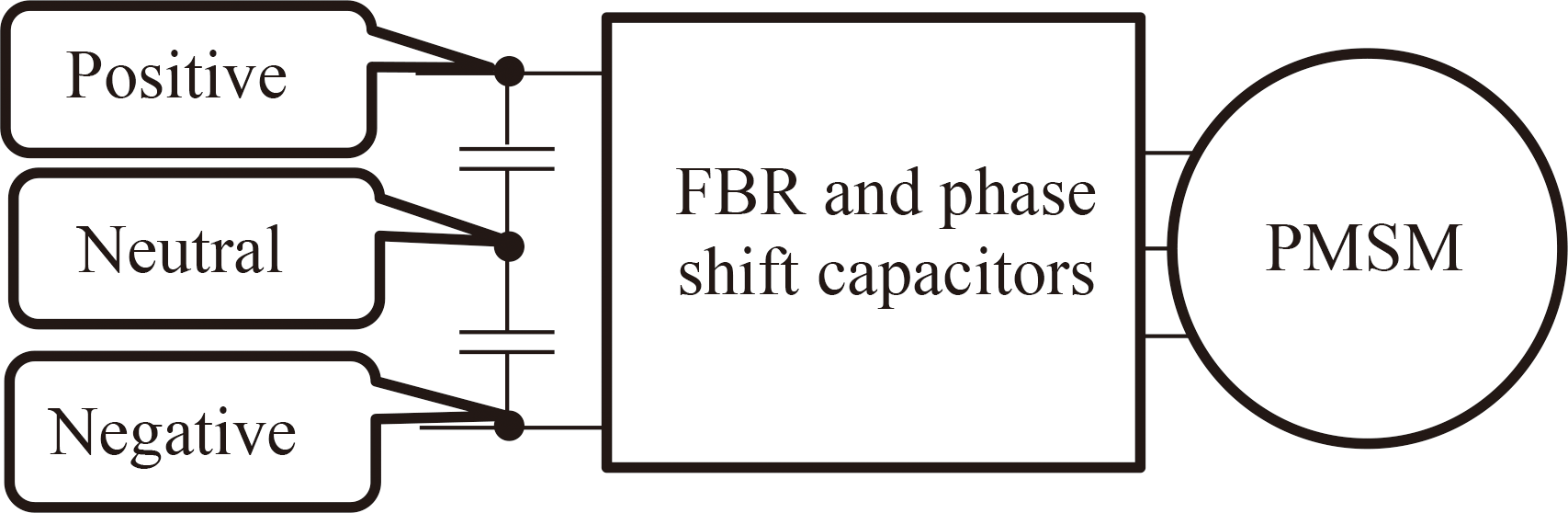
Fig. 2 Grounding location in DC power generation systems
In the case of negative grounding, the advantage is that the design of the inverter for DC EMUs can be used without modification. The advantage of neutral grounding is that the maximum voltage to ground of each part can be reduced. The maximum voltage to ground at the generator terminal is less than the sum of the positive pole voltage and the peak value of the phase-shift capacitor voltage, so the maximum voltage to ground for each part to be taken into account in the insulation design is roughly as shown in Table 1, depending on the grounding method.
Table 1 Grounding method and voltage to ground of terminals
| Grounding method | FBR terminals | Generator terminals |
| Negative | Vdc | Vdc+Vcp |
| Neutral | Vdc/2 | Vdc/2+Vcp |
Vdc : Maximum voltage of DC link
Vcp : Maximum peak value of phase shift capacitor
In this paper, the design is based on neutral grounding, which can reduce the maximum voltage to ground. For optimization, a constraint is set so that the maximum voltage to ground calculated by the formula in Table 1 does not exceed the limit value of the ground insulation used in each part. Note that in the analysis, a sinusoidal AC is assumed, even though the AC voltage of the rectifier has a roughly rectangular voltage waveform. Therefore, the fundamental wave component contained in the rectangular wave is the value of the AC voltage calculated in the analysis. Therefore, the DC voltage of the rectifier can be calculated from the AC voltage of the rectifier. In that case, if the DC voltage (which is equal to the DC voltage of the traction inverter) is Vdc and the effective value of the fundamental wave component of the rectifier AC voltage (between terminals) is Vac, the following relationship holds:
|
V
dc
=
(
π
/
6
)
V
ac
=
(
π
/
6
)
v
dr
2
+
v
qr
2
| (6) |
Therefore, the DC voltage for a certain current vector can be calculated using (1), (2), and (6).
2.2 Design problem
To verify a design method for a power generation system, it is necessary to set it a specific design problem. Therefore, we designed a power generation system assuming a hybrid vehicle or a diesel- electric vehicle. First, we assumed the following design conditions:
● Maximum engine output: 2000 rpm-300 kW.
● Maximum engine speed: 2100 rpm.
● Idling speed of the engine: 800 rpm.
● Engine speed at which the engine is highly efficient (high efficiency speed): 1400 rpm.
● Maximum output at 1400 rpm: 220 kW.
● Generator's ground insulation: for 1500 V overhead lines.
● Rectifier ground insulation: for 600 V overhead lines
● Maximum DC voltage: 650 V.
● Number of poles of the PMSM: 12.
The maximum output of the engine was determined by referring to a diesel engine with a maximum output of approximately 300 kW that is widely used in Japan. The high efficiency speed was determined by referring to the bench test results of the reference engine. The maximum output at the speed was also determined by referring to the test results. When using an engine to drive a generator, it is desirable to set the target output at less than 90% of the actual output capacity of the engine to control the rotation speed, so that the maximum output determined as a design condition is a value smaller than the actual output capacity of the engine. The insulation design of the generator is assumed to be for 1500 V DC overhead lines, which is widely used for conventional lines in Japan. Furthermore, referring to existing diesel electric vehicles, the upper limit of the DC voltage was set to 650 V with neutral grounding. In this case, the voltage to ground is a half of 650 V, so there is no problem with the ground insulation of the rectifier at 600 V. The number of poles in the PMSM was set to 12, which is the maximum number of poles that can be achieved with a 36-slot stator core and integral-slot winding that is commonly used for railway traction motors in Japan.
3. Method for designing power generation system using multi-objective optimization
3.1 Overview of the proposed design method
The essential elements that make up this power generation system are a PMSM, phase shift capacitors, and an FBR. Of these, the size of the PMSM is thought to be roughly determined by the output. On the other hand, the dimensions and weight of the phase shift capacitors depend on the required capacitance, the maximum current and voltage during operation, etc. The dimensions of the rectifier also depend on the current and voltage during operation. In the design of a normal traction inverter or a PWM converter, the current and voltage during operation are mostly determined by the voltage of the power source and the output. However, in this power generation system, these quantities are determined by the characteristics of the PMSM and the capacitance of the phase shift capacitors. Therefore, whether the power generation system can be made smaller and lighter depends strongly on the characteristics of the PMSM and the capacitance of the phase shift capacitors. Therefore, in the design of this power generation system, the aim is to make the power generation system small and lightweight, and the design variables are the parameters representing the characteristics of the PMSM and the capacitance of the phase shift capacitors. The capacitance is calculated from the q-axis inductance of the PMSM and the resonant angular frequency using equation (5), and the upper and lower limits of the resonant angular frequency can be set from the engine rotation speed. Therefore, the resonant angular frequency is used as the actual design variable rather than the capacitance. Then, the objective functions to be aimed for in the design is the maximum current during operation related to the rectifier capacity, and the kVA capacity related to the dimensions and weight of the phase shift capacitors.
Since there are two objective functions, this problem is a multi-objective optimization problem. When there are two or more objective functions, a trade-off relationship may occur between them. In that case, the goal is to obtain a set of Pareto optimal solutions, rather than a single optimal solution (a solution means a combination of design variables). In the case of multi-objective optimization, a ranking function is used as an index to select the optimal solutions. The ranking function is a function that indicates how many solutions exist for a certain solution that are superior in all objective functions. The set of solutions for which the ranking function has a value of zero are Pareto optimal solutions. In the design of this system, the trade-off relationship between the maximum current and the kVA capacity of the phase-shift capacitor is clarified by the Pareto optimal solutions, and then the final design is selected from among these solutions.
3.2 Design variables, objective functions, and constraints
This section explains how we set up the optimization problem. First, the design variables that determine the characteristics of this power generation system are shown in Table 2.
Table 2 Design variables
| Design variables |
Unit |
Lower limit |
Upper limit |
| Permanent magnet magnetic flux |
Wb |
0.0804 |
0.8038 |
| D-axis inductance |
mH |
0.1 |
10 |
| Saliency ratio |
― |
1 |
3 |
| Resonant angular frequency |
rad/s |
565.5 |
879.6 |
Table 2 also shows the lower and upper limits that define the range in which the design variables vary in the optimization. The basic characteristics of a PMSM are expressed by three variables: the permanent magnet magnetic flux, the d-axis inductance, and the q-axis inductance. However, the saliency ratio, which is the ratio of the q-axis inductance to the d-axis inductance, depends on the shape of the rotor core and cannot be varied significantly. Therefore, we decided to use the saliency ratio as a design variable instead of the q-axis inductance, and to vary it within the range of 1 to 3, which is considered feasible from our experience. The upper limit of the permanent magnet magnetic flux was set to the value where the peak value of the terminal voltage of the induced voltage generated at the maximum rotation speed of 2100 rpm is 1500 V, and the lower limit was set to 1/10 of this value. The d-axis inductance value was set to a sufficiently wide range of lower and upper limits by referring to the inductance of past prototype PMSMs. The resonant rotation speed needs to be sufficiently higher than the idling rotation speed and lower than the high efficiency speed, so the lower limit was set to the resonant angular frequency corresponding to 900 rpm which is higher than the idling rotation speed, and the upper limit was set to the resonant angular frequency corresponding to the high efficiency speed of 1400 rpm. Next, the objective functions, which are the objective of optimization, are shown in Table 3.
Table 3 Objective functions
| Objective functions |
Unit |
| Maximum current |
A |
| kVA capacity of phase shift capacitor |
kVA |
As mentioned above, the kVA capacity of the phase shift capacitor and the maximum current related to the size of the rectifier are set as the objective functions. The kVA capacities are calculated for two operating points by calculating the phase shift capacitor voltage at each operating point using the capacitance and current, then multiplying the voltage by the current. The larger of these values is set as the phase shift capacitor kVA capacity of the objective function. Furthermore, the constraints are shown in Table 4.
Table 4 Constraints
| Constraints | Unit | Lower limit | Upper limit |
| Output (high efficiency speed) | kW | 220 | ― |
| Output (maximum output speed) | kW | 300 | ― |
| DC voltage (high efficiency speed) | V | ― | 650 |
| DC voltage (maximum output speed) | V | ― | 650 |
| AC peak voltage to ground (high efficiency speed) | V | ― | 1500 |
| AC peak voltage to ground (maximum output speed) | V | ― | 1500 |
| Absolute value of the current vector | A | Ψm/Ld | 2Ψm/Ld |
First, since it is essential that the required output powers are achievable, this term is set as a constraint. When performing specific calculations, the value of the q-axis current that can achieve the required output is numerically obtained using (1) to (4). Then, the various quantities are calculated using this q-axis current and (1) to (4) etc. The upper limit of the DC voltage constraint is set to 650 V. As described later, optimization is performed to minimize the current, so the DC voltage basically tends to be as high as possible under the constraints. Therefore, it is sufficient to set only the upper limit, and there is no need for a lower limit. The constraint for the AC voltage to ground is set so that the maximum voltage to ground of the generator calculated in Table 1 is 1500 V or less. The maximum voltage to ground of the rectifier is automatically satisfied if the DC voltage constraint is satisfied, so there is no need to set it as a constraint. Finally, a constraint is set on the absolute value of the current vector during operation to ensure that the characteristics of the obtained PMSM are realizable. The lower limit value listed in Table 4 is the calculation formula for the current value corresponding to the magnetomotive force of the magnet and strongly correlated with the magnet quantity. This value was set as the lower limit because a design with a larger magnetomotive force of the magnet is likely to result in an excessive amount of magnet. Conversely, if the current vector is too large, the magnets are more likely to be demagnetized, so the upper limit was set at twice the lower limit, based on experience.
3.3 Multi-objective optimization results
As mentioned above, this optimization problem is a multi-objective optimization problem. It is known that genetic algorithms are suitable for such optimization problems, and this time we use NSGA-II [8, 9], which uses a genetic algorithm. The optimization calculation program was implemented using pymoo [8], a multi-objective optimization library written in Python. Figure 3 shows the results when the maximum population size was 100 and the number of calculation generations was changed to 100, 500, 1000, 1500, and 2000.

Fig. 3 Pareto optimal solutions
Figure 3 shows the Pareto optimal solutions obtained as a result of the multi-objective optimization, which show the trade-off relationship between the maximum current and the kVA capacity of the phase shift capacitor. Since both objective functions aim to be minimized, the individuals (solutions) on the lower left are better. The Pareto front, which is the curve drawn by the Pareto optimal solutions, has a convex shape to the lower left. A solution in the lower left of the figure that can simultaneously reduce two objective functions is a solution that cannot be obtained by single-objective optimization. In the 100th generation, there were individuals with a large maximum current despite a small phase-shift capacitor kVA capacity, and conversely, individuals with a large phase-shift capacitor kVA capacity and a small maximum current, but as the generations progressed, there was a tendency for individuals to concentrate in the lower left position. Since the values of the design variables and the objective functions are not significantly different between the individuals concentrated in the lower left, it is considered that each of these individuals has a design that is satisfactory. Therefore, among the results in the 2000th generation, the design of the individual with the smallest maximum current between the individuals concentrated in the lower left was selected as a design value. The design values are shown in Table 5. The design values in Table 5 are the values of the design variables of the selected individual, and the q-axis inductance is a value calculated using the d-axis inductance and the saliency ratio.
Table 5 Selected design values
| Items |
Unit |
Values |
| Design Variables |
Permanent magnet magnetic flux |
Wb |
0.379 |
| D-axis inductance |
mH |
0.643 |
| Q-axis inductance |
mH |
1.474 |
| Saliency ratio |
― |
2.293 |
| Resonant angular frequency |
rad/s |
565.5 |
| Objective functions |
Maximum current |
A |
341.8 |
| kVA capacity of phase shift capacitor |
kVA |
46.1 |
4. Verification of designed power generation system
4.1 Verification by analysis
This section describes how we checked the performance of the power generation system specified by the design values obtained in the previous chapter to verify the validity of the design. First, the calculation results of the current and voltage values at each operating point for the design values obtained using analytical formulas are shown in Fig. 4. The current vector curves when the load is changed at the two rotation speeds are shown in Fig. 5. Finally, changes in the current (phase current RMS value) and the voltage (terminal voltage RMS value) versus the output are shown in Fig. 6.

Fig. 4 Operating current and voltage

Fig. 5 Current vector loci when load changes

Fig. 6 Current and voltage versus load
As can be seen in Fig. 4, both the current and voltage during operation are larger at maximum output. As shown in Table 5, the current value at maximum output is 341.8 A, and the DC voltage value is 650 V, which was given as an upper limit constraint. The generator voltage is not much different from the rectifier AC voltage, and it is thought that the voltage of the phase shift capacitor is kept low to reduce the kVA capacitance of the phase shift capacitor. Secondly, in Fig. 5, we also show the curves corresponding to the maximum torque per ampere (MTPA) [10, 11], which is the operating state where the torque per current is maximum. In this design, the operation is relatively close to the MTPA at both rotation speeds, and we can expect operation at an operating point with low current and high efficiency. However, at the maximum output rotation speed, the output is approaching the output limit where the q-axis current does not increase any further. Since the possibility of reaching the output limit point increases as optimization proceeds, it is better to keep the output constraint condition at a large value during optimization because the design of the actual machine must have a margin. In Fig. 6, there is a tendency for the rectifier voltage not to change significantly even if the load increases at each rotation speed, so it is thought that a drive system can be built without problems by combining this power generation system with an ordinary traction inverter for DC overhead lines.
4.2 Verification by simulation
A simulation is then carried out using a circuit simulator to confirm the operation of the power generation system including the rectifier. A DC capacitor must be placed on the DC side of the rectifier. The capacitance of the DC capacitor sometimes has a significant effect on the operation of the power generation system. This time, we used a configuration in which two 1 mF DC capacitors are connected in series. The circuit simulator used is SystemModeler [12], which is a simulation environment that uses the Modelica language [13]. Figure 7 shows the model used for the simulation.

Fig. 7 Simulation model
In Fig. 7, “smpm” is an interior permanent magnet synchronous generator, which rotates at a constant speed due to the “constantSpeed” element. “IdealDiode” and “IdealDiode1” are diodes, and the notation “m=3” indicates that there are three phases. In other words, “IdealDiode” and “IdealDiode1” represent six diodes, and a FBR is constructed. “Capacitor1,” located between the diodes and the generator, is also written as “m=3,” indicating phase-shift capacitors for three phases. The resistor at the top is a load resistor, and the capacitors below are the DC capacitors. Between these and the diodes are elements written as “star” and “star1,” and the three phases are connected to the DC section by this star-connection element. The neutral point of the DC section is grounded to the ground element, which is used as a reference for the potentials. The simulation results shown below were carried out under two operating conditions: maximum output at the high efficiency speed (1400 rpm, 220 kW) and maximum engine output (2000 rpm, 300 kW). The load was adjusted by the load resistance value. Figure 8, 9, 10 show the calculation results for maximum output at the high efficiency speed (1400 rpm, 220 kW). The simulation was run for 0.2 seconds, and each figure plots the last 0.008 seconds.

Fig. 8 Generator current and voltage calculation results (1400 rpm-220 kW)

Fig. 9 Load resistance current and voltage calculation results (1400 rpm-220 kW)

Fig. 10 Voltage to ground calculation results (1400 rpm-220 kW)
Figure 8 shows the current and voltage of the PMSM. The current value is roughly a three-phase symmetrical sinusoidal wave, but the voltage value changes suddenly at the timing of diode switching. Figure 9 shows the current and voltage of the load resistance. There are six pulsations per cycle, which is characteristic of a FBR, but both the current and voltage are almost constant. The average current is 404 A, the average voltage is 542 V, and the generated power is about 220 kW, which is roughly consistent with the analysis results. As shown in Fig. 10, the terminal potential of the PMSM is less than 600V, which is low enough in relation to the voltage limit.
The calculation results at the maximum engine output (2000rpm, 300kW) are shown in Fig. 11, 12, 13. Again, the simulation was run for 0.2 seconds, and the final 0.008 seconds are plotted.

Fig. 11 Generator current and voltage calculation results (2000 rpm-300 kW)

Fig. 12 Load resistance current and voltage calculation results (2000 rpm-300 kW)

Fig. 13 Voltage to ground calculation results (2000 rpm-300 kW)
At maximum output, as in the case of high efficiency speed, the generating system operates as expected, and the generator current value is almost consistent with the analysis. The average current and voltage of the DC side are 493 A and 606 V, which are slightly lower than the analysis, but are roughly consistent. The voltage to ground of each part meets the constraints with a margin and is within a range that does not pose any problems in terms of the insulation configuration. Although the constraint on the AC voltage to ground was set at 1500 V, the design was such that insulation systems for 600 V would be acceptable from the viewpoint of voltage to ground.
5. Conclusion
In this paper, we proposed a method for designing a power generation system in which a phase-shift capacitor is inserted between a PMSM and an FBR, by setting the machine constants of the PMSM as design variables and performing multi-objective optimization to reduce the current capacity of the rectifier and the kVA capacity of the capacitors. The application of this method to the design of a diesel-electric vehicle enabled us to obtain a combination of machine constants that simultaneously reduces both the current capacity of the rectifier and the kVA capacity of the phase shift capacitors using a multi-objective optimization method. Furthermore, we performed a simulation to confirm the performance of a system using a PMSM with the optimized machine constants and confirmed that the design objectives of securing the target output and the limit of voltage to ground could be achieved, thus demonstrating the effectiveness of the proposed design method. Note that in this study, the machine constants of the PMSM were treated as design variables, but in general, the machine constants are determined as a result of the design and are not freely determined. It is also known that the values of the machine constants vary depending on the operating current due to the influence of magnetic saturation in the iron core. In the future, we plan to conduct a further design study of the PMSM and confirm whether the target machine constants and system operation can be achieved.
References
- [1] Nakagawa, T., Morita, E., Nishizawa, H., and Numazaki, M., “Improvement of diesel electric locomotive traction system,” presented at the 7 th World Congress on Railway Research, Montreal, Canada, June 4-8, 2006.
- [2] Watanabe, R., “Overview of the GV-E400 series new diesel-electric railcars (mass-production prototype cars),” Japanese Railway Engineering, Vol. 59, No. 1, pp. 5-8, 2019.
- [3] Umeshita, K., Yasumori, K., “Outline of battery-mounted diesel electric hybrid vehicle “YC1 Series”,” Japanese Railway Engineering, Vol. 59, No. 3 pp. 13-15, 2019.
- [4] “JR Central launches hybrid train with remote monitoring,” Railway Gazette International, 23 March, 2022.
- [5] Kondo, M., “Comparison of Two Types of DC Power Generation Systems with Permanent Magnet Synchronous Machines and Full-Bridge Rectifiers Using Resonant Circuits,” IEEJ Journal of Industry Applications, 2022, Vol. 11, No. 4, pp. 573-581, 2022.
- [6] Kondo, M., “DC Generation System with Permanent Magnet Synchronous Machine and Series Resonant Circuit,” Papers of Technical Meeting, IEE Japan, MD-21-081/RM-21-045/VT-21-006, pp. 33-38, 2021 (in Japanese).
- [7] Kondo, M., “Analyses on DC power generation systems consist of an IPMSM and a series resonant circuit,” Papers of Technical Meeting, IEE Japan, MD-23-076/RM-23-044//VT-23-006, pp. 27-32, 2023 (in Japanese).
- [8] Blank, J., and Deb, K., “pymoo: Multi-Objective Optimization in Python,” in IEEE Access, vol. 8, pp. 89497-89509, 2020.
- [9] Deb, K., Pratap, A., Agarwal, S. and Meyarivan, T. “A fast and elitist multiobjective genetic algorithm: nsga-II,” Trans. Evol. Comp, 6(2): 182-197, April 2002.
- [10] Morimoto, S., Takeda, Y., Hirasa, T. and Taniguchi, K., “Expansion of Operating Limits for Permanent Magnet Motor by Current Vector Control Considering Inverter Capacity,” IEEE Transactions of Industry Applications, Vol. 26, No. 5, pp. 866-871, 1990.
- [11] Jahns, T.M., Kliman, G.B., Neumann, T.W., “Interior Permanent-Magnet Synchronous Motors for Adjustable-Speed Drives,” IEEE Transactions of Industry Applications, Vol. IA-22, No. 4, pp. 738-747, 1986.
- [12] Wolfram system modeler, https://www.wolfram.com/system-modeler
- [13] Modelica, https://modelica.org
Author

|
Minoru KONDO, Ph.D.
Senior Chief Researcher, Head of Traction Systems Laboratory, Vehicle Technology Division
Research Areas: Traction System Design, Condition Monitoring |