Abstract
Electrochemical capacitors are energy storage devices characterized by high power and long cycle life for charging/discharging. Carbon materials play a very key role as electrode active materials for the electrochemical capacitors. This comprehensive paper mainly covers the author’s research regarding the carbon materials as electrodes for the electric double layer capacitor used as an electrochemical capacitor. The importance of focusing on the pore structure, the surface chemistry, and the three-dimensional structure of the electrodes is stated from the viewpoint of improving the energy density and reliability, and the characteristic carbon materials that have a high capacitance even with a low microporosity are also reported. These research results indicate the potential of nano-sized carbons and classic carbons, such as activated carbon and graphite-related materials, to further develop the technologies of the capacitor electrodes.
1. Introduction
Electrochemical energy storage devices, such as electrochemical capacitors and rechargeable batteries, are necessary to save fossil fuels and suppress CO2 emission. The electrochemical capacitors involve electric double layer capacitor (EDLC), redox capacitor using oxide or conductive polymers, and hybrid capacitors as shown in Fig. 1. Carbon materials are very important as the electrode for these electrochemical energy storage devices. The EDLC (Fig. 2), which is an electrochemical capacitor with the longest commercial history, store the electric charge in the dielectric layer (electric double layer) formed at the interface between the electrode and electrolyte by a non-faradaic process.1–3 The EDLC has a variety of applications because of its high capacitance, high power density, and excellent charge-discharge cycle life, which cannot be achieved with conventional electrolytic capacitors. The EDLC has the disadvantage of a low energy density compared to rechargeable batteries, but based on the technology of the EDLC, the hybrid capacitors (e.g., lithium-ion capacitor) using the electrodes of the EDLC and rechargeable battery have been developed to successfully improve the energy density of the commercialized electrochemical capacitors.4 For both the EDLC and hybrid capacitors, carbon is the key material. The author has investigated the carbon electrode for use in electrochemical capacitors for more than 20 years. This paper addresses the ideas and research results related to the carbon electrode for electrochemical capacitors.

2. Requirements of Electrode Materials for EDLC
The energy (E) stored in a capacitor is in proportion to the product of the capacitance (C) and square of the voltage (V) (E = CV2/2). Thus, it is necessary to increase the electric double layer capacitance and the maximum voltage to improve the energy density of the EDLC.5–8 The maximum voltage (withstand voltage) is basically determined by the electrochemical window of the electrolyte. Thus, the electrolyte using an aprotic organic solvent is utilized in the case of the EDLC for energy storage. For example, the electrochemical window of an aqueous electrolyte, such as dilute sulfuric acid, is about 1.2 V, while that of the organic electrolyte using propylene carbonate as the solvent is about 3 V. For the capacitance, the pore structure is significant since the double layer is charged/discharged by electrostatic adsorption/desorption of the electrolyte ions through the pores. The ion concentration in the electrolyte commercially used for the EDLC is relatively high (e.g. >1 M) to ensure a sufficient ionic conductivity, so the capacitance of the Helmholtz layer corresponding to the monolayer of adsorbed ions is the dominant variable of the overall capacitance.5 In this case, the electric double layer capacitance can be expressed as follows.
| \begin{equation}
C = \varepsilon_{0}\varepsilon_{\text{r}}S/\delta
\end{equation}
| (1) |
where
ε0 is the permittivity in a vacuum and
εr is the permittivity of the double layer.
δ is the thickness of the double layer.
S is the effective electrode surface area available for the ion adsorption/desorption. Equation (1) means that the capacitance is linearly proportional to the effective electrode surface area. Thus, the electrode materials with a high specific surface area, high electric conductivity, and electrochemical stability are necessary for the EDLC. The only material satisfying these conditions is nanoporous carbon. The commercialized EDLC uses activated carbons as practical nanoporous carbons in consideration of cost and productivity. The pore structure of the nanoporous carbons closely relates to the effective electrode surface area. Therefore, many researchers have investigated the correlation between pore structure and the capacitance with great interests.
3. Pore Structure and Double Layer Capacitance
The optimized pore structure of the activated carbon has been investigated to increase the effective electrode surface area.5–8 The optimization strategy is approximately categorized into two directions as follows. a) Enlargement of the pore width of the activated carbon to make it easy for the ion adsorption, and b) increase in specific surface area of the activated carbon. According to IUPAC’s definition of the pore classification, the pore size of micropores is smaller than 2 nm, that for mesopores is between 2 nm and 50 nm, and that for macropores is greater than 50 nm (recently, the pore with a size smaller than 100 nm is defined as nanopores9). The pores of activated carbon are developed under about 800 °C by the gasification of the carbon matrix with steam, CO2, chemical reagent, such as KOH or H3PO4, etc.8,10 The pore formation process by the gasification of carbon is referred as to “activation”. Activated carbon is strictly defined as nanoporous carbon that is produced by the gasification process (activation process). In general, the micropore is selectively generated through the activation process, resulting in a high surface area. The micropores of the activated carbon are considered as a nanospace with a distorted slit-like nanospace formed between small fractions of the hexagonal carbon planes (micrographite).8
In the case of the organic electrolyte for the EDLC, the ion size is around 1 nm, so it is close to that of the micropore. For tetraethylammonium tetrafluoroborate ((C2H5)4NBF4) as typical electrolyte salt, the ion diameter of the cation ((C2H5)4N+) is around 0.7 nm and that of the anion (BF4−) is around 0.5 nm.11,12 This suggested that electrolyte ion cannot be smoothly adsorbed in the narrow micropores, thus promoted the research focusing on the mesopores, which is related to direction (a) (Enlargement of the pore width of the activated carbon). In fact, it was observed that the double layer capacitance is very low when the micropores are smaller than the electrolyte ion. This phenomenon is referred as to “ion sieving”.5–8,13–16 The nanoporous carbon with developed mesopores, which is referred as to “mesoporous carbon”, is effective for suppression of the ion sieving by the micropores.5–8,12–16 The author revealed that the mesoporous carbons prepared by catalytic activation14,15 or defluoronation of polytetrafluoroethylene (PTFE)17–24 show suppression of the ion sieving and a high rate performance as shown in Fig. 3.23,24 However, the volumetric capacitance, which is the specific capacitance normalized by the electrode volume, of the mesoporous carbons is not high because the mesopores decrease the bulk density of the electrode.7,8 The volumetric capacitance is more important than the gravimetric capacitance (the specific capacitance normalized by the electrode weight) from the viewpoint of energy storage.25,26 Similarly, the volumetric energy density is more significant than the gravimetric energy density for the electrochemical capacitors. Therefore, the mesoporous carbon is not the only way to improve the energy density of the EDLC.

Direction (b), the increase in the specific surface area of the activated carbon, is also a difficult way to increase the volumetric capacitance and energy. Figure 4 shows the correlation between the specific surface area and the double layer capacitance that the author previously evaluated.7,8 The specific surface area is approximately proportional to the gravimetric capacitance except in the region of the low specific surface area influenced by the ion sieving effect. This indicates that the gravimetric capacitance of the activated carbon electrode basically follows Eq. (1). However, the volumetric capacitance shows a convex curve with a maximum value. The development of the pore structure by the activation process increases not only the specific surface area but also the pore width to decrease the bulk density. The convex curve in Fig. 4(b) is due to the trade-off of the increase in the gravimetric capacitance and the decrease in the bulk density with an increasing specific surface area. This is the reason for the difficulty of direction (b).

The volumetric capacitance estimated from an ideal nanoporous carbon, in which a single carbon hexagonal sheet (graphene) is stacked with a minimum distance for the ion adsorption, is suggestive of limitation to improve the volumetric capacitance by the pore-structure optimization. When the proportionality constant (ε0εr/δ) in Eq. (1), which is the specific capacitance normalized by the surface area, is the same (7–8 µF cm−2) as that of the activated carbons, the ideal nanoporous carbon with a 0.8 nm slit-like pore width is expected to have the volumetric capacitance of 120–140 F cm−3. (Fig. 5).8,27 This is only about twice that of the typical coconut-shell based activated carbon for the EDLC. This suggests that the volumetric capacitance and energy density cannot be essentially improved by the control of the pore structure of the activated carbon electrode.
4. Research Direction other than Optimization of the Pore Structure
Based on the described background, the author is presently investigating a different direction of carbon research for the capacitor from the optimization of the pore structure. This review addresses the following examples.
-
• Nano-sized carbons (carbon nanotube, carbon nanofiber, fullerene-related material, graphene, etc.)
-
• Approach for high voltage charge (Heteroatom doping, Seamless structure)
-
• Low porous carbons
The hybridization of a redox material with a porous carbon electrode is also a way to increase the volumetric capacitance, but the author focuses on enhancing the potential of the carbon materials, especially, classic carbons, such as activated carbon and graphite-related materials, which are advantageous for practical use in terms of cost and productivity.
4.1 Nano-sized carbons
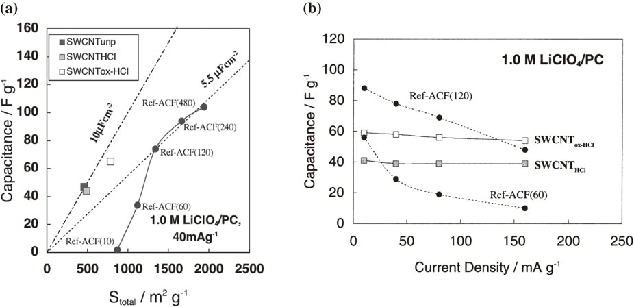
The carbon nanotube (CNT) is the first nano-sized carbon28 evaluated as the EDLC electrode material. The CNT is an ideal nanoporous carbon with cylinder-like pores. During the initial research stage before the author started evaluating the capacitance properties of the CNT, it had been already reported that the CNT shows a greater capacitance than the activated carbons.29 However, the CNT usually used in those days was not well purified, so the electrochemical property of the CNT was not clear. Therefore, the author carefully evaluated the capacitance property of the pure CNT and the conventional activated carbon under the same measurement conditions.30,31 Figure 6(a) shows the correlation of the capacitance and the specific surface area of the single-walled carbon nanotube (SWCNT) synthesized by HiPco® and the activated carbon fiber in a propylene carbonate electrolyte.30 The HiPco®-SWCNT, which has very few carbon particles (e.g., graphite and soot) other than the CNTs in spite of a lot of Fe catalysts, was one of highest quality available at that time. The theoretical specific surface area of the SWCNT is 2630 m2 g−1, but the actual value is often less than 1000 m2 g−1 because of the bundle structure and the closed inner space of the tube. The gravimetric capacitance of the HiPco®-SWCNT is not high, however, the specific capacitance per surface area is higher than that of activated carbon. It is a characteristic property of the SWCNT electrode for the EDLC. Furthermore, the SWCNT electrode shows the higher rate property versus the activated carbon as shown in Fig. 6(b). The good rate performance of the SWCNT is due to the smooth adsorption/desorption path of the electrolyte ions, which is different from the case of the activated carbon with a complicated pore structure. After the author’s research using the HiPco®-SWCNT, the EDLC using SWCNT electrodes has been further developed with the advent of the “Super-growth method” that can synthesize ultra-pure SWCNTs.32 Recently, the author revealed that the SWCNT prepared by the super-growth method is much more stable to the durability test with a high voltage floating charge than the HiPco®-SWCNT (Fig. 7).33 To utilize the SWCNT as the EDLC electrode, the removal of impurities, such as metal catalysts and low-crystalline carbons, should not be ignored.
The main way to increase the voltage of the EDLC was originally to design the electrolyte with a wide electrochemical window. However, the actual electrochemical window depends not only on the electrolyte, but also the electrode material. The withstand voltage of the EDLCs is influenced by the crystallinity, pore structure, and surface chemistry of the carbon nanoporous electrode.34,35 This is because the surface of the nanoporous carbon electrode has a catalytic activity for the electrochemical decomposition of the electrolyte. Thus, to increase the maximum charge voltage of the EDLC, the nanoporous carbon electrode also has to be optimized.
4.2.1 Nitrogen-doping
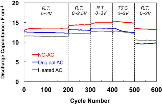
In general, a surface treatment can modify the electrochemical properties of the carbon electrode. For the EDLC, the surface modification of the nanoporous carbon electrode has been investigated in order to increase the capacitance. Especially, nitrogen doping, which corresponds to forming nitrogen-containing surface functional groups, is the focus of the technique for the electrode modification of the EDLC. However, nitrogen doping is not always effective in increasing the capacitance, particularly, when using an organic electrolyte. The author fortunately determined that the nitrogen doping can stabilize the activated carbon electrode for the high voltage charging,7,8,34,36–38 while oxygen-containing surface functionalities degrades the electrode.39 Figure 8 shows the change in the capacitance of the EDLC cell using the nitrogen-doped activated carbon electrode during the galvanostatic charge-discharge cycle test.7,8,34) The capacitance of the pristine activated carbon electrode is still almost unchanged in the voltage region of 0–2 or 2.5 V at room temperature, but that deceased under aggressive conditions (0–3 V at 70 °C). The durability against a high voltage charge at high temperature around 70 °C is significant for the energy density and reliability of the EDLC. The EDLC using activated carbon nitrogen-doped by the heat-treatment with nitrogen-monoxide (NO) has a better durability compared to those of the pristine and simply heated (in inert gas) activated carbons. The nitrogen-doping by NO is the substitution reaction of carbon atom with nitrogen atom.40 Figure 9 is the N1s X-ray photoelectron spectra (XPS) of the nitrogen-doped carbon.7 This indicates that the nitrogen atom is mainly doped as a pyridine-like functionality41 and the nitrogen functionality is relatively stable to the high voltage charging. Recently, another research group also reported that the surface modification with NO is effective for the improvement of the durability and the rate performance.42 The electrochemical stability is the key to finding the effective surface modification for the improvement of the operating voltage of the nanoporous carbon electrode.
Charging the EDLC beyond the withstand voltage causes electrochemical decomposition at the electrode interface that markedly decreases the capacitance, thereby leading to decrease in the energy density. The mechanism of the capacitance decline is complicated, but the possible factors are shown as follows.
-
(a)
Pore blockage by decomposition deposits and gas39,43–47
-
(b)
Destruction and deformation of capacitor cell by the decomposition gas48
-
(c)
Breakdown of electric network of electrode (decease in electronic conductivity of electrode by binder decomposition and deposition of decomposition product)27,34,47
Factor (a) is the reason for the decreasing effective electrode surface area available for the ion adsorption/desorption. Factor (b) is a critical problem for commercial EDLCs, which is realistically protected by a safety valve. The suppression of the electrolyte decomposition is basically necessary. Factor (c) is related to the three-dimensional structure of the activated carbon electrode. Figure 10(a) shows a schematic illustration and scanning electron microscopy (SEM) image of the conventional EDLC electrode. This is a complicated composite structure in which nanoporous carbon particles, conductive additives, and binders are intertwined with each other. For this composite electrode, the electronic conductivity is sufficiently high before any severe operation. However, high voltage charging causes the decomposition of the binder, loosening the electric connection between the particles, and insulating the interface between the particles and the contact point with the current collector by depositing decomposition products. The decrease in the electronic conductivity, i.e., the increase in the internal resistance of the electrode reduces the power output. Based on the above drawbacks of the conventional composite electrode, the author concluded that the three-dimensional structure of the electrode is important for strengthening the electric network of the electrode, and developed a “seamless activated carbon electrode” with excellent durability against high-voltage charging as the electrode for electrochemical capacitors.27,34,49 The seamless activated carbon electrode is a monolith of nanoporous carbon, which is now commercialized as “CROUS®” from AION Co., Ltd.50 Figure 10(b) shows a schematic illustration and SEM of the seamless activated carbon electrode. Unlike conventional composite electrodes consisting of activated carbon particles, the seamless activated carbon electrodes are free of the interface between the particles, including the conductive additive. Therefore, the degradation related to the contact resistance between the carbon particles never occurs in principle. The EDLC using the seamless activated carbon electrode shows a high capacitance retention of 80 % after the durability test with a floating condition (3.5 V, 100 h, 70 °C), which is aggressive and actually important to know the durability of the EDLC,51 while that using the conventional activated carbon electrode has a lower retention of less than 20 %.27,34,49 This shows that the seamless structure is effective for improving the durability against high voltage charging of the EDLC. However, since the seamless activated carbon electrode has a catalytic activity for the electrochemical decomposition reaction as well as conventional activated carbon, the capacitance decline accompanied with deposition of the decomposition products has not been suppressed. This issue can be alleviated by surface modification (e.g., nitrogen-doping) of the electrode. Figure 11 shows the rate performance of the EDLC using the seamless activated carbon electrode or the nitrogen-doped activated carbon electrode.49 The rate of the EDLC after the durability with the floating condition (3.5 V, 100 h, 70 °C) is improved by using the seamless structure compared to that using the composite electrode and its improvement is further enhanced by the nitrogen doping of the seamless activated carbon electrode. This is due to the suppression of the micropore blockage and contact-resistance increase caused by electrochemical decomposition during high-voltage charging as shown in Fig. 12.

Other groups also reported that binder-free electrodes of the SWCNT or graphene52,53 and the seamless nanoporous carbon electrode prepared by the template method54 are effective for the electrode stability during the high voltage charging. Therefore, it is concluded that the optimization of the electrode structure and the surface condition design leads to realizing a durable EDLC.
4.3 Low porous carbons
Low porous carbons were originally unsuitable as an electrode active material for the EDLC. As shown in Fig. 4, the double layer capacitance is almost linear to the specific surface area of the electrode, so a highly-porous carbon with a high specific surface area is advantageous for the EDLC. However, some low porous carbons,55,56 which have a relatively high bulk density, show a comparable gravimetric capacitance and higher volumetric capacitance compared to the highly porous carbons. The author reported that the carbon product derived from the chemical defluoronation of graphite-fluoride (GF) with a charge-transfer complex (e.g., a lithium naphthalenide) has a high capacitance regardless of its low microporosity (< about 100 m2 g−1).23,24 The GF is a covalent-type graphite intercalation compound (GIC)57 and used as a lubricant and cathode material of primary lithium batteries.58 The GF-Li primary ((CF)n/Li) battery has been commercially used due to its high energy density and low self-discharge property. The battery reaction is as follows.59
| \begin{align*}
&(\text{Cathode})\quad (\text{CF})_{\text{n}} + \text{nLi$^{+}$} + \text{ne$^{-}$}\to \text{nC} + \text{nLiF}\notag\\
&(\text{Anode})\quad \text{Li}\to \text{Li$^{+}$} + \text{e$^{-}$}
\end{align*}
|
The cathode of the discharged GF-Li battery is known to be composed of a nano-composite of carbon and LiF.60 Several years ago, the author noticed that this cathode discharge-product of the GF-Li battery is analogous to the carbon product derived from the defluoronation of the GF as already mentioned. This leads to the author’s idea that the cathode discharge-product of the GF-Li battery can also work as the active material of an electrochemical capacitor. Thus, it was revealed that the discharged GF-Li battery can be re-charged as a new hybrid electrochemical capacitor.61 The discharge-charge curves of the GF-Li battery are shown in Fig. 13. The first discharge-curve has a plateau around 2.5 V, which is a characteristic of the GF-Li battery. The successive charge-discharge curves show a triangle shape, which means a capacitive performance. This suggests that the carbon/LiF nano-composite as the discharge-product of the cathode operates as the positive electrode of the capacitor and that the Li metal is electrochemically deposited/dissolved at the negative electrode (Fig. 14). The author terms this new hybrid capacitor system as the “Graphite-Fluoride Lithium (GF-Li) Capacitor”. The GF-Li capacitor has a higher energy density and power density than the EDLC and the performance is comparable to that of the Li-ion capacitor as shown in Fig. 15. The charge-discharge mechanism of the discharged GF electrode was analyzed by the inductively coupled plasma optical emission spectroscopy, ion chromatography, and electrochemical quartz crystal microbalance.61 As a result, it was revealed that the Li+ cation is doped/undoped into the nano-composite of carbon and LiF. This analytical result and the low microporosity of the electrode suggest the Li+ adsorption/desorption on the surface of the small-sized carbon crystallite with wide interspace by the diffusion between the LiF nano-particles.

Recently, the author also determined that the primary Li battery using graphite-oxide (GO) as a covalent-type GIC62,63 also functions as a hybrid electrochemical capacitor as well as the GF-Li battery. The volumetric capacitance and the energy density of the hybrid capacitor derived from the GO-Li battery64 is better than those of the GF-Li capacitor.65 Thus, the less porous carbons derived from the covalent-type GIC are interesting as the electrode materials for electrochemical capacitors.
5. Conclusion
The author has reviewed the idea of using the carbon electrode for electrochemical capacitors. Presently, only optimization of the pore structure of the carbon electrode is difficult to improve the volumetric capacitance and energy density of the carbon-based capacitor including the EDLC. The author believes that not only nano-sized carbons but also classic carbons, such as activated carbon and GIC, have a great potential to successfully bring technological innovation of electrochemical capacitors.
Acknowledgment
The author would like to express sincere gratitude to Prof. Emeritus Zen-ichiro Takehara, Prof. Kiyoshi Kanamura, Prof. Emeritus Yasuhiko Ito, Prof. Emeritus Tsuyoshi Nakajima, Prof. Emeritus Asao Oya, Prof. Jun-ichi Ozaki, and Assist. Prof. Yoshikiyo Hatakeyama, many colleagues, students, postdoctoral researcher, staffs, and collaborators. The financial support from MEXT, JST, JSPS, NEDO, and many foundations is deeply appreciated. The study related to seamless activated carbons were conducted as collaborative research with AION Co., Ltd.
Funding Information
Japan Society for the Promotion of Science: 26410250
Japan Society for the Promotion of Science: 17H03123
Japan Society for the Promotion of Science: 21K05255
Footnotes
S. Shiraishi: ECSJ Active Member
References
- 1) B. E. Conway, Electrochemical Supercapacitors - Scientific Fundamentals and Technological Applications, Springer, New York (1999).
- 2) P. Simon and Y. Gogotsi, Nat. Mater., 7, 845 (2008).
- 3) F. Béguin, V. Presser, A. Balducci, and E. Frackowiak, Adv. Mater., 26, 2219 (2014).
- 4) K. Naoi and P. Simon, Interface, 17(1), 34 (2008).
- 5) S. Shiraishi, Hyomen, 40, 13 (2002). [in Japanese]
- 6) S. Shiraishi, J. Jpn. Inst. Energy, 81, 788 (2002). [in Japanese]
- 7) S. Shiraishi, Key Eng. Mater., 497, 80 (2011).
- 8) S. Shiraishi, Encyclopedia of Applied Electrochemistry (Eds. R. F. Savinell, K. Ota, and G. Kreysa), Springer Nature, New York, p. 1 (2014).
- 9) M. Thommes, K. Kaneko, A. V. Neimark, J. P. Olivier, F. Rodriguez-Reinoso, J. Rouquerol, and K. S. W. Sing, Pure Appl. Chem., 87, 1051 (2015).
- 10) H. Marsh and F. Rodríguez-Reinoso, Activated Carbon (Eds. H. Marsh and F. Rodríguez-Reinoso), Elsevier, p. 243 (2006).
- 11) M. Ue, J. Electrochem. Soc., 141, 3336 (1994).
- 12) S. Shiraishi, Tanso, 2007, 237 (2007). [in Japanese]
- 13) L. Eliad, G. Salitra, A. Soffer, and D. Aurbach, J. Phys. Chem. B, 105, 6880 (2001).
- 14) S. Shiraishi, H. Kurihara, L. Shi, T. Nakayama, and A. Oya, J. Electrochem. Soc., 149, A855 (2002).
- 15) S. Shiraishi, H. Kurihara, and A. Oya, Electrochem, 69, 440 (2001).
- 16) S. Shiraishi, Y. Aoyama, H. Kurihara, A. Oya, and Y. Yamada, Mol. Cryst. Liq. Cryst., 388, 129 (2002).
- 17) S. Shiraishi, H. Kurihara, H. Tsubota, A. Oya, S. Soneda, and Y. Yamada, Electrochem. Solid-State Lett., 4, A5 (2001).
- 18) T. Liang, Y. Yamada, N. Yoshizawa, S. Shiraishi, and A. Oya, Chem. Mater., 13, 2933 (2001).
- 19) Y. Yamada, O. Tanaike, T.-T. Liang, H. Hatori, S. Shiraishi, and A. Oya, Electrochem. Solid-State Lett., 5, A283 (2002).
- 20) O. Tanaike, N. Yoshizawa, H. Hatori, Y. Yamada, S. Shiraishi, and A. Oya, Mol. Cryst. Liq. Cryst., 388, 45 (2002).
- 21) O. Tanaike, N. Yoshizawa, H. Hatori, Y. Yamada, S. Shiraishi, and A. Oya, Carbon, 40, 457 (2002).
- 22) O. Tanaike, H. Hatori, Y. Yamada, S. Shiraishi, and A. Oya, Carbon, 41, 1759 (2003).
- 23) S. Shiraishi and O. Tanaike, Advanced Fluoride-Based Materials for Energy Conversion (Eds. T. Nakajima and H. Groult), Elsevier, Oxford, p. 415 (2015).
- 24) S. Shiraishi, Tanso, 2016, 75 (2016). [in Japanese]
- 25) T. Morimoto, Tanso, 2004, 202 (2004). [in Japanese]
- 26) Y. Gogotsi and P. Simon, Science, 334, 917 (2011).
- 27) S. Shiraishi and Y. Hatakeyama, Vac. Surf. Sci., 62, 703 (2019). [in Japanese]
- 28) M. Inagaki and L. R. Radovic, Carbon, 40, 2279 (2002).
- 29) C. Liu, A. J. Bard, F. Wudl, I. Weitz, and J. R. Heath, Electrochem. Solid-State Lett., 2, 577 (1999).
- 30) S. Shiraishi, H. Kurihara, K. Okabe, D. Hulicova, and A. Oya, Electrochem. Commun., 4, 593 (2002).
- 31) S. Shiraishi, M. Kibe, T. Yokoyama, H. Kurihara, N. Patel, A. Oya, Y. Kaburagi, and Y. Hishiyama, Appl. Phys. A, 82, 585 (2006).
- 32) D. N. Futaba, K. Hata, T. Yamada, T. Hiraoka, Y. Hayamizu, Y. Kakudake, O. Tanaike, H. Hatori, M. Yumura, and S. Iijima, Nat. Mater., 5, 987 (2006).
- 33) I. Shimabukuro, Y. Hatakeyama, and S. Shiraishi, Electrochem, 88, 369 (2020).
- 34) S. Shiraishi, Bol. Grupo Español Carbón, 28, 18 (2013).
- 35) S. Shiraishi and Y. Hatakeyama, Tanso, 2019, 154 (2019). [in Japanese]
- 36) D. Salinas-Torres, S. Shiraishi, E. Morallón, and D. Cazorla-Amorós, Carbon, 82, 205 (2015).
- 37) S. Shiraishi, S. Kawaguchi, I. Shimabukuro, and Y. Hatakeyama, Tanso, 2019, 139 (2019). [in Japanese]
- 38) M. J. Mostazo-López, R. Ruiz-Rosas, T. Tagaya, Y. Hatakeyama, S. Shiraishi, E. Morallón, and D. Cazorla-Amorós, C, 6, 56 (2020).
- 39) D. Cazorla-Amorós, D. Lozano-Castelló, E. Morallón, A. Linares-Solano, and S. Shiraishi, Carbon, 48, 1451 (2010).
- 40) T. Suzuki, T. Kyotani, and A. Tomita, Ind. Eng. Chem. Res., 33, 2840 (1994).
- 41) E. Raymundo-Piñero, D. Cazorla-Amorós, and A. Linares-Solano, Carbon, 41, 1925 (2003).
- 42) Sutarsis, J. Patra, C.-Y. Su, J. Li, D. Bresser, S. Passerini, and J.-K. Chang, ACS Appl. Mater. Interfaces, 12, 32797 (2020).
- 43) P. Azaïs, L. Duclaux, P. Florian, D. Massiot, M.-A. Lillo-Rodenas, A. Linares-Solano, J.-P. Peres, C. Jehoulet, and F. Béguin, J. Power Sources, 171, 1046 (2007).
- 44) P. W. Ruch, D. Cericola, A. Foelske, R. Kötz, and A. Wokaun, Electrochim. Acta, 55, 2352 (2010).
- 45) S. Ishimoto, Y. Asakawa, M. Shinya, and K. Naoi, J. Electrochem. Soc., 156, A563 (2009).
- 46) Y. Liu, B. Soucaze-Guillous, P.-L. Taberna, and P. Simon, J. Power Sources, 366, 123 (2017).
- 47) S. Muroi, D. Iida, T. Tsuchikawa, N. Yabuuchi, R. Horikoshi, N. Hosono, D. Komatsu, and S. Komaba, Electrochem, 83, 609 (2015). [in Japanese]
- 48) R. Kötz, P. W. Ruch, and D. Cericola, J. Power Sources, 195, 923 (2010).
- 49) T. Tagaya, Y. Hatakeyama, S. Shiraishi, H. Tsukada, M. J. Mostazo-López, E. Morallón, and D. Cazorla-Amorós, J. Electrochem. Soc., 167, 060523 (2020).
- 50) https://www.st.gunma-u.ac.jp/20180516-cbshiraishi/ referred on May 16, 2018.
- 51) D. Weingarth, A. Foelske-Schmitz, and R. Kötz, J. Power Sources, 225, 84 (2013).
- 52) A. Izadi-Najafabadi, S. Yasuda, K. Kobashi, T. Yamada, D. N. Futaba, H. Hatori, M. Yumura, S. Iijima, and K. Hata, Adv. Mater., 22, E235 (2010).
- 53) Y. W. Chi, C.-C. Hu, H.-H. Shen, and K.-P. Huang, Nano Lett., 16, 5719 (2016).
- 54) K. Nomura, H. Nishihara, N. Kobayashi, T. Asada, and T. Kyotani, Energy Environ. Sci., 12, 1542 (2019).
- 55) M. Takeuchi, K. Koike, T. Maruyama, A. Mogami, and M. Okamura, Denki Kagaku (presently Electrochemistry), 66, 1311 (1998).
- 56) S. Mitani, S.-I. Lee, S.-H. Yoon, Y. Korai, and I. Mochida, J. Power Sources, 133, 298 (2004).
- 57) Y. Sato, K. Itoh, R. Hagiwara, T. Fukunaga, and Y. Ito, Carbon, 42, 2897 (2004).
- 58) K. Guérin and M. Dubois, Advanced Fluoride-Based Materials for Energy Conversion (Eds. T. Nakajima and H. Groult), Elsevier, Oxford, p. 261 (2015).
- 59) M. S. Whittingham, J. Electrochem. Soc., 122, 526 (1975).
- 60) H. Touhara, H. Fujimoto, N. Watanabe, and A. Tressaud, Solid State Ionics, 14, 163 (1984).
- 61) I. Shimabukuro, T. Kawashima, Y. Shiraishi, N. Katagiri, Y. Hatakeyama, and S. Shiraishi, Electrochemistry, 89, 87 (2021).
- 62) T. Nakajima and Y. Matsuo, Carbon, 32, 469 (1994).
- 63) A. Lerf, H. He, M. Forster, and J. Klinowski, J. Phys. Chem. B, 102, 4477 (1998).
- 64) P. Touzain, R. Yazami, and J. Maire, J. Power Sources, 14, 99 (1985).
- 65) I. Shimabukuro, N. Katagiri, Y. Hatakeyama, and S. Shiraishi, Tanso, 2021, 76 (2021).
Biographies

Soshi Shiraishi (Professor, Graduate School of Science and Technology, Gunma University)
Soshi Shiraishi was born in 1970. He graduated from Graduate School of Engineering, Kyoto University in March 1995, and earned Doctor of Energy Science in 1999. He worked in Gunma University as Research Associate in 1997–2006 and was promoted to Associate Professor in 2006 and Professor in 2013. He was awarded Young Researcher Award (Sano Award) from The Electrochemical Society of Japan in 2006. His research interests are carbon-based electrochemical devices such as electrochemical capacitors and lithium batteries.
Hobby: experiments, reading comics.


