Abstract
There is growing demand for the energy storage devices with superior energy density than that of conventional lithium-ion batteries. Lithium-air batteries (LABs) are promising candidates for next-generation rechargeable batteries due to their extremely high theoretical energy density. In recent several years, there are many research progress for LABs mainly in the field of academia. However, in most of the studies, the performance evaluation of LABs is performed under inappropriate technological parameters from the viewpoint of the high energy density cell design. As results, the cell-level energy density of LABs is lower than conventional lithium-ion batteries. For realizing the cell-level high energy density LABs, such as 500 Wh/kg class LABs, the cell should be operated under lean electrolyte and high areal capacity condition and the suitable electrode materials and electrolyte should be developed. This article over-views the recent research progress of LABs, from the viewpoint of practical cell design and material development. In addition, the perspective for future research direction for realizing LABs with practically high energy density and long cycle life is also described.
1. Introduction
In recent years, demand for the development of rechargeable batteries with high energy density has been increasing. Although researchers who develop lithium-ion batteries (LiBs), which have been used since 1991, have responded well to market needs, the theoretical energy density of conventional LiBs does not meet the requirements of advanced energy storage devices with an energy density greater than 500 Wh/kg, which is critical for next-generation vehicles such as plug-in hybrid and electric vehicles. Therefore, to develop energy storage devices with substantially higher energy densities, a new operating principle that differs from that of LiBs should be developed. Lithium–air batteries (LABs) are a promising technology for next-generation rechargeable batteries because of their high theoretical energy density. LABs use metallic lithium, which has a low redox potential of −3.04 V (vs. standard hydrogen electrode (SHE)) and a high theoretical capacity of 3860 mAh/g, and atmospheric O2 as active materials.1,2 For example, assuming the operating voltage of 2.7 V, an energy density of 10422 Wh/kg can be attained based on the mass of lithium metal (3860 mAh/g). This value corresponds with energy density based on the active material (not include the mass of oxygen in atmosphere) before discharge condition. In contrast, an energy density of 3150 Wh/kg also can be obtained based on the mass of Li2O2 (1168 mAh/g), which corresponds with energy density after discharge condition. Even at the cell-level, LABs can achieve an energy density two to five times greater than that of LiBs. In fact, LABs with cell level energy density over 500 Wh/kg have already been demonstrated,3,4 and this potential of LABs for high energy density is promising. Although numerous studies have been devoted to the discovery of new materials and reaction mechanisms for LABs, LABs remain in their infancy because of problems such as a short cycle life and low power density. Over the past few decades, enormous progress has been achieved in LAB technology from the viewpoint of materials science, including the development of a stable electrolyte against oxygen reactive species, hierarchical porous carbon electrodes, and a protective layer for lithium metal electrodes.1,2 In addition, studies involving advanced analytical techniques have clarified the chemical/electrochemical reaction mechanism in LABs. However, LABs remain far from commercialization and further fundamental studies are necessary for the practical implementation of this technology. In this article, the design strategy for cell-level high energy density LABs is described, with particular focus on the importance of evaluating LAB cells under lean electrolyte and high areal capacity conditions. In addition, recent progress in the development of electrolytes, which are a critical component for extending the cycle life of LABs, is summarized.
2. Strategies for Cell-level High Energy Density LABs
2.1 Energy density simulation
A typical LAB comprises a lithium metal foil, separator, Li-ion-conducting organic electrolyte, porous carbon electrode, and gas diffusion layer (Fig. 1). During the discharge process, Li is oxidized at the negative electrode and the generated electrons are transported through an external circuit to the positive electrode, where they are used for reducing atmospheric O2. The Li ions generated at the negative electrode are transported to the positive electrode through the electrolyte and form insoluble Li2O2 as a discharge product at the positive electrode, and vice versa. The redox reactions during the discharge process are represented as follows:
| \begin{equation}
\text{Positive electrode:}\ \text{O$_{2}$} + \text{2Li$^{+}$} + \text{2e$^{-}$} \rightleftharpoons \text{Li$_{2}$O$_{2}$}
\end{equation}
| (1) |
| \begin{equation}
\text{Negative electrode:}\ \text{Li} \rightleftharpoons \text{Li$^{+}$} + \text{e$^{-}$}
\end{equation}
| (2) |
On the basis of the reaction 2Li + O
2 $ \rightleftharpoons $ Li
2O
2, the energy density of LAB is over 10000 Wh/kg, based on the mass of active material of lithium metal (not include the mass of oxygen in atmosphere). However, in practical condition, the cell components, such as electrolyte in the separator and porous carbon electrode, also taken into account for estimating energy density based on the mass of whole LAB cell. Thus, in order to investigate how the LAB energy density is affected by the amount of electrolyte in the separator and porous carbon electrode, an energy density simulation was performed.
5 The details of cell components used for energy density simulation is summarized in Table
1. When a glass-fiber separator (thickness = 100 µm, porosity = 91 %) commonly used in LAB studies was employed, the energy density was less than 300 Wh/kg, even at an areal capacity of 6 mAh/cm
2, because a large amount of electrolyte (as much as 24 µL/cm
2) was required to fully fill the pore spaces in the separator. The electrolyte accounted for >62 % of the total weight (Fig.
2a), which resulted in a low energy density. When a polyolefin-based separator (thickness = 20 µm, porosity = 46 %) commonly employed in commercial LiBs was used, the energy density exceeded 400 Wh/kg because the electrolyte loading decreased to 0.89 µL/cm
2. The simulation also revealed that the energy density increased with decreasing electrolyte amount (i.e., decreasing volume fraction) in the porous carbon electrode. For example, the energy density increased from 414 to 610 Wh/kg when the electrolyte loading decreased from 13.5 to 2.7 µL/cm
2 (from 100 % to 20 % volume fraction). In a cell with an energy density of 610 Wh/kg, the electrolyte accounted for 15 % of the total weight of the cell components (Fig.
2b). Such a high energy density was attained using a carbon electrode with a high capacity of 6000 mAh/g
carbon. When a carbon electrode with a capacity of 2000 mAh/g was used, the energy density of the LAB was less than 202 Wh/kg. A large amount of electrolyte is required to fully fill the pore spaces of the carbon electrode, thereby lowering the energy density of the cell.
Table 1. The details of cell components used for energy density simulation.
| |
thickness |
porosity |
density |
| mm |
% |
mg/cm2 |
| Lithium foil |
0.05 |
0 |
2.67 |
| Cupper foil |
0.005 |
0 |
4.50 |
| Porous carbon electrode |
0.15 |
90 |
5.00 |
| Gas diffusion layer |
0.11 |
80 |
4.11 |
| Current collector |
0.045 |
0 |
1.30 |
| Glass fiber separator |
0.26 |
91 |
5.12 |
| Polyorefin separator |
0.02 |
45 |
1.08 |
2.2 Electrolyte filling technology
The electrolyte filling technique used in LiBs can potentially be applied to LABs because complete filling of the voids of the porous carbon electrode with electrolyte should be avoided to preserve oxygen transport channels. In addition, to maximize the energy density, the electrolyte volume fraction in the porous carbon electrode should be controlled. The LAB energy density can be maximized by reducing this fraction as much as possible without compromising battery performance. Despite the importance of the electrolyte filling process in the development of high-performance LiBs, the technology related to the electrolyte filling process in LABs remains underexplored. To achieve a highly uniform electrolyte distribution even for relatively small electrolyte volume fractions, we focused on the inkjet technique, which employs a piezoelectric element to emit nanoliter-scale electrolyte droplets.5 In addition, the use of a robotic arm allows such small electrolyte droplets to be emitted with a pitch of several hundred micrometers. These characteristics are advantageous for achieving electrolyte filling with high two-dimensional uniformity. As another technique for the electrolyte filling process, we used two highly hydrophilic filters as electrolyte transfer agents, which enables the uniformly spread electrolyte to be transferred to the carbon electrode sandwiched between them (Fig. 3).5 The high porosity of the filters resulted in uniform electrolyte injection into the carbon electrode.

The realization of an LAB with high energy density requires a porous carbon electrode with high capacity. In particular, the hierarchical pore structure of the carbon electrode should be properly designed. In the positive electrode reaction, the Li2O2 generated during the discharge process accumulates on the pores of the carbon electrode. Therefore, a carbon electrode is required to ensure sufficient pore capacity for storing the deposited Li2O2. In addition, for efficient O2 reduction under a relatively high current density, interconnected micron-sized macropores should be formed to enhance O2 transport through the carbon electrode.6 Among electrodes based on carbon materials, those using carbon nanomaterials such as carbon nanotubes (CNTs) and graphene showed excellent performance as positive electrodes in LABs.7,8 In addition to exhibiting a high specific surface area, they enabled the fabrication of free-standing membranes without a polymetric binder, thereby maximizing the carbon content of the electrode. By focusing on using a non-solvent-induced phase separation method, we recently developed a method for preparing a self-standing carbon membrane with a connected pore structure, which provides mass transport channels through the electrode.3
The phase separation method is a technique for producing a porous membrane; it exploits the difference in solubility of polymer materials in a solvent as a driving force for pore structure formation.9 We prepared a carbon-based self-standing membrane by mixing carbon black powder, carbon fibers, and a polymer material as a film-constituting element. In this case, the carbon fibers were used to improve the mechanical strength of the prepared membrane and the polymer material functioned as an adhesive for the carbon particles. A slurry containing a suitable ratio of the polymer and carbon material was prepared and formed into a membrane by a doctor-blading technique. A photograph of the prepared carbon membrane is shown in Fig. 4a, demonstrating its self-standing characteristic.3 Notably, when a carbon-black-based self-standing membrane was used as the positive electrode in an LAB, the cell exhibited a capacity of >7000 mAh/gelectrode at a current density of 0.4 mA/cm2. In addition, the method developed for preparing self-standing carbon membrane was also applicable to various carbon materials,10,11 revealing the novelty of the proposed method.

Using the developed self-standing carbon electrode, we fabricated a 500 Wh/kg class LAB cell; its discharge/charge properties were subsequently evaluated.3 The cell exhibited a stable voltage at ∼2.65 V during the discharging process (Fig. 4b). In addition, the cell exhibited a charging profile typical of LABs. The initial charging voltage was approximately 3.2–3.5 V, and the charging voltage gradually increased to 4.0 V. Although a stable discharge/charge reaction occurred during cycles 1–4, the charging efficiency decreased to 60 % in the 5th cycle and 40 % in the 6th cycle. As a result, the discharge voltage decreased at the 6th cycle. At the 7th cycle, the discharge voltage reached a cutoff condition of 1.5 V. Herein, we estimate the cell-level energy density of an LAB reported in the literature.12 Figure 5 shows a plot of the estimated energy density and cycle number during the discharge/charge tests. Although the literature contains numerous reports of the successful operation of an LAB with prolonged discharge/charge processes for more than 100 cycles, their energy density at the practical cell-level was less than 50 Wh/kg.12

Although we demonstrated a 500 Wh/kg LAB that exhibits stable discharge/charge cycles at room temperature, its cyclability was still less than 10 cycles. Realizing an LAB with a practically high energy density and long cycle life necessitates a deep understanding of the complicated reaction in LABs. In particular, the problems specifically associated with the limited electrolyte conditions in LABs need to be considered. Although the importance of investigating negative Li electrodes in lean-electrolyte systems has been recognized in recent years, specific problems associated with the negative Li electrode in an LAB have not yet been studied. In particular, chemical crossover from the positive electrode to the negative electrode is a critical problem that needs to be addressed.
To attain deep insight into the reaction mechanisms at both the positive and negative electrodes, we used a three-electrode setup in which the potentials of the two electrodes can be tracked independently.4 The representative voltage profile of LAB was shown in Fig. 6a. There can be seen the gradual increase of over-potential in both discharge and charge process. At 20th cycle, discharge voltage reached cutoff condition and the cell stopped. Figure 6b shows potential profiles for the positive and negative electrodes against the reference electrode. Stable potential profiles were observed for both electrodes during cycles 1–5. The negative Li electrode exhibited voltage plateaus at −50 mV during discharging and +50 mV during charging, suggesting stable Li dissolution/deposition reactions. A profile similar to that for the full cell setup was observed for the positive oxygen electrode. The positive electrode continued to show a stable profile, even until the 20th cycle. By contrast, the negative Li electrode showed a complicated potential profile. A higher overpotential was observed at the end of the charging process (Li deposition) during the 8th cycle, which is associated with Li deposition. This overpotential continued to increase over 700 mV at the 10th charging process, resulting in a clear peak. At the 20th cycle, a sharp increase in the potential in the negative electrode was observed at the end of the discharging process (Li dissolution) and the cutoff voltage of 1.0 V was reached, suggesting that electrochemically active Li had been depleted in the negative electrode. Importantly, such a complicated voltage profile was not observed in a symmetric Li/Li cell setup in an O2 atmosphere (Fig. 6c), which showed a stable voltage profile and an overpotential of less than 100 mV, even at the 20th cycle. These results clearly reveal that the decrease in discharge voltage observed for the LAB cell at the 20th cycle originated from an increase in overpotential at the negative electrode.

Notably, an in situ mass spectrometry (MS) analytical experiment revealed that such poor reaction efficiency at the negative electrode occurred because of the crossover of chemicals such as H2O and CO2 from the positive oxygen electrode.4 On the basis of this mechanistic understanding, we fabricated an LAB with an ultra-lightweight, flexible, ceramic-based, solid-state separator with a thickness 6 µm (Fig. 7a); this separator effectively protected the Li electrode against chemical crossover without diminishing the energy density of the LABs. As a result, a 400 Wh/kg-class LAB exhibited a stable discharge/charge process for more than 20 cycles (Figs. 7b and 7c).
3. Electrolyte for Extending the Cycle Life of LABs
By the use of suitable self-standing porous carbon membrane as positive electrode, we successfully demonstrated the operation of 500 Wh/kg class LABs. In additions, the introduction of flexible light-weight protective layer for lithium metal electrode is effective for suppressing the side reaction in negative electrode, resulting in the stable discharge/charge reaction over 20 cycles. In addition, C-rate also should be improved for adequate high power density operation and quick charging, in order to satisfy the requirement for various use of energy storage devices. For further improvement of the cycle life of LABs with practically high energy density cell design, the improvement of reaction efficiency at both oxygen positive electrode and lithium metal negative electrode is crucial by the suppression of the electrolyte decomposition.13 In this section, recent our progress for the development of electrolyte for LABs are summarized.
3.1 Ether solvent
Although a stable electrolyte has not yet been found, tetraethylene glycol dimethyl ether (TEGDME or tetraglyme) is the most popular solvent for LAB electrolytes because of its relatively high stability against both oxygen positive electrodes and lithium metal negative electrodes, as well as its suitable physicochemical characteristics (e.g., viscosity, freezing point, boiling point, vapor pressure, and oxygen solubility) and good cell performance. However, the sever solvent decomposition reaction proceeds under LAB operation condition. Recent operando analysis revealed the formation of ethylene glycol methyl ether (2-methoxyethanol), ethylene glycol methyl methoxymethyl ether, and smaller glymes such as CH3O(CH2CH2O)nCH3 (1 ≤ n ≤ 3) as byproducts.14 Thus, development of a novel electrolyte is crucial for practical application of LAB technology. In addition, for the improvement of performance of LAB, the introduction of additives is also effective approach. In particular, the additives are effective for improving power density by suitably controlling the Li2O2 formation pathway in discharge process and for decreasing over-potential by function as soluble catalyst.
3.1.1 Promoter for solution pathway of Li2O2 formation
The Li2O2 formation pathway during discharge can be roughly divided into direct and solution pathways, depending on the degree of interaction between the reaction intermediate LiO2 and the electrolyte. Here, for a solvent with a relatively large interaction with LiO2 (i.e., a high-donor number (DN) solvent, such as sulfoxide solvents like dimethyl sulfoxide (DMSO)), the LiO2 generated by the one-electron reduction reaction of O2 is dissolved in the electrolyte. A solvated complex containing Li+ and O2 is then formed (* indicates a surface-adsorbed species):
| \begin{equation}
\text{O$_{2}$} + \text{e$^{-}$} \rightleftharpoons \text{$^{*}$O$_{2}$}
\end{equation}
| (3) |
| \begin{equation}
\text{Li$^{+}$} + \text{$^{*}$O$_{2}$} \rightleftharpoons \text{$^{*}$LiO$_{2}$}
\end{equation}
| (4) |
| \begin{equation}
\text{$^{*}$LiO$_{2}$} = \text{sLiO$_{2}$ (solvated complex: [solvent]$_{n}$[Li$^{+}$][O$_{2}$])}
\end{equation}
| (5) |
The solvated complex formed is then converted to Li
2O
2 via a disproportionation reaction (solution pathway):
| \begin{equation}
\text{2sLiO$_{2}$} \rightleftharpoons \text{Li$_{2}$O$_{2}$} + \text{O$_{2}$}
\end{equation}
| (6) |
By contrast, for a solvent with a relatively small interaction with LiO
2 (low-DN solvent, such as ether solvents like TEGDME), the produced LiO
2 is immediately reduced on the electrode to generate Li
2O
2 (surface pathway):
| \begin{equation}
\text{$^{*}$LiO$_{2}$} + \text{Li$^{+}$} + \text{e$^{-}$} \rightleftharpoons \text{2Li$_{2}$O$_{2}$}
\end{equation}
| (7) |
The mechanism of Li
2O
2 formation strongly influences the discharge capacity of LABs. In a low-DN solvent, Li
2O
2 accumulates on the carbon electrode surface; the discharge capacity then gradually decreases. In a high-DN solvent, Li
2O
2 formation proceeds at a location away from the electrode surface; thus, the Li
2O
2 is deposited onto the electrode surface. A high discharge capacity can be attained without a coating. However, high-DN solvents are unstable against nucleophilic attack by the O
2 generated as a reaction intermediate, which is disadvantageous for long-term cycling.
15 Although a high-DN solvent can lead to a high capacity, its poor stability remains problematic.
One approach to overcoming the aforementioned problem is to control the state of the solvated complex by introducing an additive. The solvated complex shown in Eq. 5 can be controlled to promote Li2O2 production via the solution pathway, even in an electrolyte composed of a low-DN solvent. For example, the reaction pathway for Li2O2 production can be shifted by adding water to the electrolyte.16 Although water cannot be used as an additive for electrolytes in practical LABs because water rigorously reacts with lithium metal electrodes, the results suggest that the discharge capacity can be improved by controlling the state of the solvated complex by introducing an additive.
The effectiveness of alkali-metal cations as additives to improve the discharge capacity in an electrolyte composed of a low-DN solvent has been previously investigated. For example, when K+ ions were added to a TEGDME-based electrolyte, the discharge capacity dramatically improved.17 The authors attributed this result to the added K+ ions forming a stable solvate complex and shifting the equilibrium of Eq. 5 to the right, thereby switching the formation of Li2O2 from the surface to the solution pathway:
| \begin{equation}
\text{Solvated complex: }\text{[solvent]$_{n}$[Li$^{+}$][O$_{2}$]}\ldots\text{ [K$^{+}$]}
\end{equation}
| (8) |
Equation 8 shows that the stability of the solvate complex depends on the degree of electron donation of K
+ to O
2 (Lewis basicity). In fact, when a cation with a lower Lewis basicity (i.e., weaker electron donation to O
2 than to K
+) is added, the switch to the solution pathway does not proceed effectively, resulting in a limited improvement in the discharge capacity. Given that the addition of metal cations can effectively improve the performance of lithium metal electrodes, these additives are promising for practical use in LABs.
3.1.2 Soluble catalyst
The introduction of an electrode catalyst can effectively advance the electrochemical reaction at the oxygen positive electrode. An improved electrode reaction rate can, in turn, improve the power density and energy efficiency of the LAB. A large overpotential during the charging process at the oxygen positive electrode induces side reactions, such as the decomposition of the electrolyte and the carbon electrode, thereby decreasing the energy efficiency and the cycle life of LABs. Therefore, decreasing the overpotential during repeated discharge/charge processes is critical for improving LAB performance. However, in the case of metal- or metal-oxide-based solid catalysts, which are typically grafted onto the surface of a carbon electrode, the surface of the catalysts is covered with the Li2O2 formed during the discharge process, resulting in catalyst deactivation. Soluble catalysts, also called redox mediators, can be used to solve this problem. When a chemical species that can be dissolved at high concentrations in the electrolyte is used as the catalyst, the problem related to passivation by Li2O2 can be avoided in principle.
Quinone derivatives are representative examples of soluble catalysts for the discharge process (Fig. 8).18 In an electrolyte containing a quinone compound, the following reactions proceed under an Ar atmosphere:
| \begin{equation}
\text{Q$_{\text{ox}}$} + \text{Li$^{+}$} + \text{e$^{-}$} \rightleftharpoons \text{Q$_{\text{sem}}$Li}
\end{equation}
| (9) |
| \begin{equation}
\text{Q$_{\text{sem}}$Li} + \text{Li$^{+}$} + \text{e$^{-}$} \rightleftharpoons \text{Q$_{\text{red}}$Li$_{2}$}
\end{equation}
| (10) |
If O
2 is introduced into the system, O
2 reacts with Q
semLi, forming soluble LiO
2 (sLiO
2)
| \begin{equation}
\text{Q$_{\text{sem}}$Li} + \text{O$_{2}$} \rightleftharpoons \text{Q$_{\text{ox}}$} + \text{sLiO$_{2}$}
\end{equation}
| (11) |
The generated sLiO
2 forms a solvated complex in the electrolyte and is converted to Li
2O
2 via the solution pathway (Eq. 7). In the reaction mechanism described by Eqs. 9–11, O
2 is not generated as a reaction intermediate in the reaction that produces Li
2O
2 via a quinone compound. Because O
2− is one of the main products of the side reaction, the introduction of a soluble catalyst not only reduces the reaction overvoltage but also reduces the side reaction.
19

As soluble catalysts for the charging reaction, cyclic metal complexes such as metal phthalocyanine and porphyrin complexes are promising candidates because of their high design flexibility (redox potential and solubility in electrolytes). In particular, cobalt phthalocyanine with tert-butyl ligands has been reported to be an efficient soluble catalyst for the charging process in LABs.20 The effects of tert-butyl ligands include (i) shifting the redox potential to the negative side on the basis of the electron-donating effect on the central metal and (ii) improving the solubility of the complex by enhancing its interaction with the solvent. In addition, nitroxyl radicals, such as 2,2,6,6-tetramethylpiperidine 1-oxyl (TEMPO), have also been reported as potential soluble catalysts in the charging reaction.21 However, given the long cycle life required for LABs, concerns have arisen regarding the stability of organic compounds. Therefore, a soluble catalyst composed of an inorganic compound is ideal. Redox couples such as I−/I3−, Br−/Br3−, and NO2−/NO2 have redox potentials that make them appropriate soluble catalysts for Li2O2 decomposition, and their application to LABs has therefore been investigated.22,23 Although the combination of LiNO3 and LiBr has been recognized as an effective redox mediator for improving the performance of LABs,24 details of the reaction mechanism remain unknown. In a recent study, the complex chemical reactions at the positive electrode of an LAB containing LiNO3 and LiBr under high areal capacity and lean electrolyte conditions were comprehensively investigated using several ex situ and in situ techniques.25 The formation of bromoform and other Br-containing organic compounds such as 1-bromo-2-methoxyethane and 1-bromo-2,2-methoxyethoxyethanein was confirmed, suggesting complex side reactions involving Br−.
3.2 Amide solvent
Historically amides have generally been considered unsuitable as solvents for LAB electrolytes because they are prone to decomposition by O2−. However, recent studies revealed that amide has ability to quench the generation of singlet oxygen (1O2) and form highly decomposable Li2O2.26,27 For these unique properties, amide again get attention as alternative option for promising electrolyte for LAB. Actually, stable discharge/charge cycles more than 80 cycles at a current density of 0.1 mA/cm2 have been obtained by using lithium nitrate with dimethylacetamide as the electrolyte.28 However, the challenges related to the poor stability against a lithium metal electrode remain unsolved. In the following section, the strategy for improving the reaction efficiency of amide-based electrolyte in lithium metal negative electrode is summarized.
3.2.1 Fluorinated compounds as additives or co-solvent
Reversible deposition/dissolution of lithium metal occurs at the lithium-electrode side during repeated charging and discharging. The fresh lithium metal generated during cycling reacts with the electrolyte components to form an insulating layer (solid electrolyte interface; SEI) at the interface between the electrode and the electrolyte. In principle, an SEI layer with sufficient Li-ion conductivity and mechanical flexibility can permit structural changes of the lithium metal during deposition/dissolution with minimal side reactions. The use of SEI-forming additives is an effective approach to overcome this issue and prolong the cycling of the lithium metal electrode.29 Although the use of fluorinated amide solvent as an additive assist in the formation of a stable SEI, thereby enhancing the stability of the electrolyte against metallic lithium,30 the reversibility of the lithium metal electrode requires further improvements without diminishing the reaction efficiency at the positive-electrode side. A recent our study has demonstrated that addition of fluorinated co-solvent, bis(2,2,2-trifluoroethyl) ether (BTFE), has promising effects for improving the performance of LABs.31 These electrolytes were prepared by dissolving LiNO3 into N-methylpyrrolidone (NMP) and adding bis(2,2,2-trifluoroethyl) ether (BTFE). Notably, LAB cells constructed using 4 M LiNO3 in NMP with a 50 vol% BTFE electrolyte displayed stable discharge/charge behavior at a high current density of 1.0 mA/cm2 and a high areal capacity of 2.0 mAh/cm2. Analyses revealed that the superior performance of the cell was attributable to the unique characteristics of the nitrate/amide-based localized high-concentration electrolytes. Specifically, the improvement of the reversibility of the Li deposition/dissolution reaction was achieved as a result of the formation of an LiF-rich SEI via decomposition of BTFE in an O2 atmosphere. In addition, the electrolytes accelerate the solution route formation of Li2O2, which results in the formation of a large toroidal Li2O2 structure.
3.2.2 Multi-component additives discovered by high throughput robotic experiment
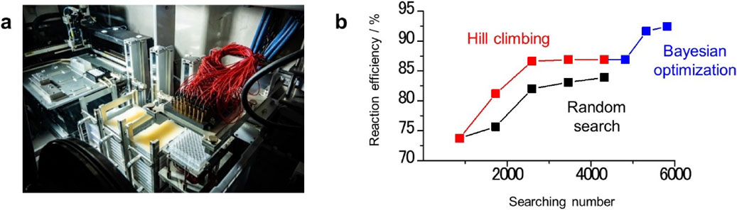
The design of electrolyte additives that contribute to the formation of an SEI film via the cooperative effect of multiple compounds is one of effective approach for realizing a stable long-term cycle reaction of lithium metal negative electrodes.32 The most appropriate combination can be clarified using an automated robotic experiment. A recent study demonstrated a combinatorial high-throughput evaluation of electrolytes with a screening rate greater than 1000 samples/day (Fig. 9a). In the search for electrolyte additives that use such automated robotic experiments, the effective use of data scientific method can accelerate the discovery of an ideal electrolyte composition. For example, when 5 of 15 chemical types are selected in conjunction with 2 concentrations with duplicates, more than 107 candidates are possible. Thus, comprehensively evaluating all the possible combinations is not feasible even with such a high-throughput experimental setup. Therefore, a specific electrolyte composition that realizes superior battery performance must be determined with only a limited number of experimental trials. Actually, in our recent study, established machine-learning methodologies based on Bayesian optimization were used to solve combinatorial optimization problems for analyzing datasets obtained from automated robotic experiments, thereby minimizing the number of trials required to identify the ideal electrolyte composition (Fig. 9b).33 As results, we identified the specific electrolyte composition (1.5 M LiNO3, 0.1 M lithium bis(trifluoromethanesulfonyl)imide, 0.1 M LiBr, 0.5 mM LiCl, and 10 mM lithium bis(oxalate)borate in dimethylacetamide, with 5 vol% 1,3-dioxolane) that enhanced the discharge/charge performance of the LABs, realizing stability over 100 cycles with capacity of 0.5 mAh/cm2. The electrolyte discovered through this strategy was comprehensively analyzed, and it was confirmed that the improved uniformity of the deposited lithium metal, which was realized via synergy among the various components of the electrolyte, was found to be primarily responsible for the improved reaction efficiency. The methodology demonstrated in this study is a viable strategy for accelerating the discovery of extremely useful multicomponent electrolytes that are difficult to identify using more conventional bottom-up approaches.
Phosphate ester solvents have been widely investigated as electrolytes for LiBs because of their high oxidation resistance and nonflammability. We investigated triethylphosphate (TEP) based electrolytes in LABs to possibly avoid the side reactions by the reactive oxygen species, which could lead to highly efficient oxygen evolution and enhanced life span of the batteries. Although several investigations have been conducted on TEP-based electrolytes with regard to use in LABs,34,35 their performance is infancy. Actually, when a TEP-based electrolyte containing LiNO3 and TEP formed a solvated complex by coordinating with Li+ ions, the O2 evolution rate reached nearly 100 % of that for the ideal two-electron reaction during most of the charging process, with the total oxygen evolution yield exceeding 90 %.36 By contrast, a carbon electrode was not stable, especially against the reactive oxygen species generated. The electrode decomposed to form Li2CO3 as a byproduct that accumulated in its pores. This side reaction is a critical problem that must be addressed for LABs with high energy densities to be developed.36
4. Summary and Outlook
In this article, the main factors for the development of battery materials for LABs was surveyed from the viewpoint of practical cell design. Most previously reported studies on materials development for LABs have been conducted with an excess amount of electrolyte inside the cell (>50 µL/cm2) and with the cell operating under a small areal capacity (<0.5 mAh/cm2). The results indicated that the energy density in actual cells is less than 100 Wh/kg. Achieving LABs with an energy density that exceeds that for conventional LiBs requires further development of electrode materials and electrolytes under lean electrolyte (<20 µL/cm2) and high areal capacity (>2 mAh/cm2) conditions (Fig. 10). In the two decades since Abraham et al.’s 1996 report of a prototype battery system,37 the development of LABs has attracted intensive attention. However, the battery performance should be further improved to enable the practical implementation of LABs. In particular, for improving the cycle life of LABs with high energy density, suppressing side reactions is critical. In addition to the conventional approach for materials development, the approach using a data-driven method is also effective for accelerating the discovery of LAB materials. Instead of relying on the experience and intuition of researchers, MI can, in principle, reduce the time and cost of material discovery. Collaborative studies involving both materials science and data science can accelerate the practical implementation of LABs.

CRediT Authorship Contribution Statement
Shoichi Matsuda: Conceptualization (Lead), Funding acquisition (Lead), Supervision (Lead), Writing – original draft (Lead), Writing – review & editing (Lead)
Conflict of Interest
The authors declare no conflict of interest in the manuscript.
Footnotes
S. Matsuda: ECSJ Active Member
References
- 1) W.-J. Kwak, Rosy, D. Sharon, C. Xia, H. Kim, L. R. Johnson, P. G. Bruce, L. F. Nazar, Y.-K. Sun, A. A. Frimer, M. Noked, S. A. Freunberger, and D. Aurbach, Chem. Rev., 120, 6626 (2020).
- 2) T. Liu, J. P. Vivek, E. W. Zhao, J. Lei, N. Garcia-Araez, and C. P. Grey, Chem. Rev., 120, 6558 (2020).
- 3) S. Matsuda, E. Yasukawa, T. Kameda, S. Kimura, S. Yamaguchi, Y. Kubo, and K. Uosaki, Cell Rep. Phys. Sci., 2, 100506 (2021).
- 4) S. Matsuda, M. Ono, H. Asahina, S. Kimura, E. Mizuki, E. Yasukawa, S. Yamaguchi, Y. Kubo, and K. Uosaki, Adv. Energy Mater., 13, 2203062 (2023).
- 5) S. Matsuda, S. Yamaguchi, E. Yasukawa, H. Asahina, H. Kakuta, H. Otani, S. Kimura, T. Kameda, Y. Takayanagi, A. Tajika, Y. Kubo, and K. Uosaki, ACS Appl. Energy Mater., 4, 2536 (2021).
- 6) A. N. Mistry, F. Cano-Banda, D. Law, A. Hernandez-Guerrero, and P. P. Mukherjee, J. Mater. Chem. A, 7, 8882 (2019).
- 7) A. Nomura, K. Ito, and Y. Kubo, Sci. Rep., 7, 45596 (2017).
- 8) Y. Lin, B. Moitoso, C. Martinez-Martinez, E. D. Walsh, S. D. Lacey, J.-W. Kim, L. Dai, L. Hu, and J. W. Connell, Nano Lett., 17, 3252 (2017).
- 9) G. R. Guillen, Y. Pan, M. Li, and E. M. V. Hoek, Ind. Eng. Chem. Res., 50, 3798 (2011).
- 10) J. Saengkaew, T. Kameda, M. Ono, and S. Matsuda, Mater. Adv., 3, 3536 (2022).
- 11) J. Saengkaew, T. Kameda, M. Ono, E. Mizuki, S. Nagaishi, S. Iwamura, S. R. Mukai, and S. Matsuda, J. Phys. Chem. C, 127, 939 (2023).
- 12) S. Matsuda, M. Ono, S. Yamaguchi, and K. Uosaki, Mater. Horiz., 9, 856 (2022).
- 13) M. Ono, J. Saengkaew, and S. Matsuda, Adv. Sci., 2300896, Early View <https://doi.org/10.1002/advs.202300896>.
- 14) M. Ue, H. Asahina, S. Matsuda, and K. Uosaki, RSC Adv., 10, 42971 (2020).
- 15) A. Khetan, A. Luntz, and V. Viswanathan, J. Phys. Chem. Lett., 6, 1254 (2015).
- 16) N. B. Aetukuri, B. D. McCloskey, J. M. Garciá, L. E. Krupp, V. Viswanathan, and A. C. Luntz, Nat. Chem., 7, 50 (2015).
- 17) S. Matsuda, Y. Kubo, K. Uosaki, and S. Nakanishi, J. Phys. Chem. Lett., 8, 1142 (2017).
- 18) S. Matsuda, K. Hashimoto, and S. Nakanishi, J. Phys. Chem. C, 118, 18397 (2014).
- 19) X. Liu, P. Zhang, L. Liu, J. Feng, X. He, X. Song, Q. Han, H. Wang, Z. Peng, and Y. Zhao, ACS Appl. Mater. Interfaces, 12, 10607 (2020).
- 20) S. Matsuda, S. Mori, K. Hashimoto, and S. Nakanishi, J. Phys. Chem. C, 118, 28435 (2014).
- 21) B. J. Bergner, A. Schürmann, K. Peppler, A. Garsuch, and J. Janek, J. Am. Chem. Soc., 136, 15054 (2014).
- 22) H. D. Lim, H. Song, J. Kim, H. Gwon, Y. Bae, K. Y. Park, J. Hong, H. Kim, T. Kim, Y. H. Kim, X. Leprõ, R. Ovalle-Robles, R. H. Baughman, and K. Kang, Angew. Chem., Int. Ed., 53, 3926 (2014).
- 23) Z. Liang and Y.-C. Lu, J. Am. Chem. Soc., 138, 7574 (2016).
- 24) X. Xin, K. Ito, and Y. Kubo, ACS Appl. Mater. Interfaces, 9, 25976 (2017).
- 25) M. Ono and S. Matsuda, J. Phys. Chem. C, 127, 6117 (2023).
- 26) K. Nishioka, M. Tanaka, H. Fujimoto, T. Amaya, S. Ogoshi, M. Tobisu, and S. Nakanishi, Angew. Chem., Int. Ed., 61, e202112769 (2022).
- 27) K. Nishioka, M. Saito, M. Ono, S. Matsuda, and S. Nakanishi, ACS Appl. Energy Mater., 5, 4404 (2022).
- 28) W. Walker, V. Giordani, J. Uddin, V. S. Bryantsev, G. V. Chase, and D. Addison, J. Am. Chem. Soc., 135, 2076 (2013).
- 29) E. Peled and S. Menkin, J. Electrochem. Soc., 164, A1703 (2017).
- 30) V. S. Bryantsev, V. Giordani, W. Walker, J. Uddin, I. Lee, A. C. T. van Duin, G. V. Chase, and D. Addison, J. Phys. Chem. C, 117, 11977 (2013).
- 31) M. Ono and S. Matsuda, ACS Appl. Energy Mater., 6, 3357 (2023).
- 32) S. Matsuda, K. Nishioka, and S. Nakanishi, Sci. Rep., 9, 6211 (2019).
- 33) S. Matsuda, G. Lambard, and K. Sodeyama, Cell Rep. Phys. Sci., 3, 100832 (2022).
- 34) Z. E. M. Reeve, A. D. Pauric, K. J. Harris, and G. R. Goward, J. Phys. Chem. C, 119, 26840 (2015).
- 35) Z. E. M. Reeve, A. D. Pauric, K. J. Harris, and G. R. Goward, J. Phys. Chem. C, 119, 26840 (2015).
- 36) S. Matsuda and H. Asahina, J. Phys. Chem. C, 124, 25784 (2020).
- 37) K. M. Abraham and Z. Jiang, J. Electrochem. Soc., 143, 1 (1996).
Biographies

Shoichi Matsuda (Team Leader, Automated Electrochemical Experiments Team, Center for Green Research on Energy and Environmental Materials, National Institute for Material Science)
Shoichi Matsuda was born in 1987. He studied chemistry in The University of Tokyo and received his PhD in 2015. After that, he joined NIMS as an ICYS (International Center for Young Scientists) researcher and then got a tenured position in 2017.


