Articles
Performance Stabilization of Lithium-Sulfur Batteries Containing Sulfolane-based Electrolyte and Microporous Cathode by Controlling Working Voltage Range

2023 Volume 91 Issue 6 Pages 067002

Details
2023 Volume 91 Issue 6 Pages 067002
For lithium-sulfur (Li-S) batteries, high-concentration electrolyte that inhibits the dissolution of Li polysulfide has been widely studied; one such electrolyte contains sulfolane. This study investigates the conditions under which a microporous activated carbon cathode, derived from azurmic acid, operates stably in a sulfolane-based electrolyte. We expected this cathode to maintain a stable capacity in a sulfolane-based electrolyte because its micropores stabilize the S species. However, Li-S batteries containing this cathode and electrolyte exhibit significant capacity decay during cycling. The cutoff voltage during charge-discharge cycling is varied to suppress the capacity decay. At a discharge voltage of 1.4 V or lower, the cycle life of the Li-S batteries is significantly reduced. Conversely, increasing the cutoff voltage during discharge suppresses the capacity decay of Li-S batteries. On the other hand, increasing the upper voltage limit during charging increases the reversible capacity. Thus, the operating voltage range is optimized. This study indicates that the voltage range of Li-S batteries should be carefully determined depending on the type of cathode material and electrolyte.
Since commercializing lithium (Li)-ion batteries in 1991, the demand for battery devices with better energy densities has increased. The intercalated materials used in current Li-ion batteries are expected to reach their energy-density limits soon. In addition, there are concerns about the depletion of metals, such as cobalt and nickel, which are widely used as cathodes in Li-ion batteries. The possibility that global conditions will significantly affect their prices is a major concern for the future development of Li-ion batteries.
Extensive research has been conducted on Li-sulfur (Li-S) batteries since the 1970s to increase energy density and circumvent resource depletion.1,2 S is the active cathode material of Li-S batteries, which is lightweight, resource-abundant, and inexpensive. It is attracting attention as a next-generation rechargeable battery material owing to its high theoretical cathode capacity of 1672 mAh g−1. The redox reaction is based on a two-electron transfer reaction per sulfur atom (S8 + 16Li+ + 16e− → 8Li2S).3,4
The dissolution of Li polysulfide during charging and discharging and the large capacity decrease with cycling hinder the realization of Li-S batteries.5,6 Adding Li nitrate to an electrolyte is a widely known countermeasure for the dissolution of Li polysulfide during charging and discharging. Li nitrate enables the stable operation of Li-S batteries by forming a “solid electrolyte interface (SEI)” that protects the Li-metal anode. However, adding Li nitrate raises concerns regarding the limited voltage range, limited dosage, and safety of side products.7 We have previously reported Li-S batteries with S-adsorbed microporous activated carbon as a cathode to address these limitations. These can be stably charged and discharged for various electrolytes without adding Li nitrate.8–10 Nano-sized pores strongly adsorb Li polysulfide because of the capillary phenomenon.11 In particular, activated carbon with very small pores with a diameter of 2 nm or less, “micropores,” can suppress the dissolution of Li polysulfide in an electrolyte.
Although the choice of electrolytes compatible with micropores is essentially wide, we have reported concerns about the access of electrolytes to such micropores, particularly in high-concentration electrolytes containing high amounts of Li salts and in localized high-concentration electrolytes (LHCEs).12 In recent years, much research has been conducted to adapt LHCEs to Li-S batteries.13–17 LHCE has a reduced viscosity while maintaining a solvation structure in high concentration by dilution with hydrofluoroether (HFE), which has low solubility for Li salt and Li polysulfide. Watanabe et al. reported a glyme-based electrolyte, lithium bis(trifluoromethylsulfonyl)imide (LiTFSI) : tetraglyme(G4) : HFE = 10 : 8 : 40 mol, and a sulfolane-based electrolyte, LiTFSI : sulfolane : HFE = 1 : 2 : 2 mol, as LHCEs to achieve considerably reversible charge/discharge without adding Li-nitrate.15
Investigating and improving other degradation factors is necessary to realize Li-S batteries because capacity decay is still associated with charge/discharge cycles even with these electrolytes. This study provides insight into the causes of capacity decay of Li-S batteries using LHCEs. It offers a simple improvement measure effective in LHCE containing sulfolane,12 which is controlling operating voltage range. This control enhances the performance of the microporous activated carbon-S composite cathode to suppress Li polysulfide dissolution.
AZC was prepared using the procedure reported in our previous reports.9,10 Azurmic acid (AZA) was carbonized at 800 °C for 1 h under a nitrogen atmosphere. The obtained AZA carbides were mixed with an alkali activator (KOH) in a weight ratio of 1 : 2 in deionized water, stirred at 100 °C for 5 h, and dried. Subsequently, the mixture was activated at 800 °C for 1 h in a quartz tube (3 cm in diameter) under an argon atmosphere. The activated product was dispersed in deionized water and neutralized using dilute hydrochloric acid. The sample was filtered, washed with excess deionized water, and vacuum dried at 80 °C for at least 12 h to obtain AZC.
2.2 S-filled AZC (AZC-S) and AZC-S cathode preparationAZC (0.4 g) and S (0.6 g) were mixed in an agate mortar and placed in a simple stainless-steel (SUS) reaction vessel. The mixture was heated to 155 °C in an air atmosphere and held for 5 h to melt S and allow it to diffuse spontaneously into the AZC pores. The temperature was further increased from 155 to 300 °C and held for 2 h to remove excess S outside the pores of AZC. Each temperature elevation was performed at a rate of 10 °C min−1, while temperature was allowed to reduce to room temperature by air cooling. The complex of AZC with S obtained through this process was denoted as AZC-S. The amount of S confined in the AZC pores was calculated from its pore volume using nitrogen adsorption/desorption measurements.
A slurry was prepared by mixing AZC-S, carbon nanotubes (CNT), carboxymethyl cellulose (CMC), and styrene butadiene rubber (SBR) in an 89 : 5 : 3 : 3 weight ratio in water to form the S cathode. The slurry was coated on an Al foil using the doctor-blade method and dried in an oven at 40 °C for at least 3 h. Residual water was removed by drying in a vacuum oven at 50 °C for at least 12 h. The S content of the electrode was approximately 3.0 mg cm−2.
2.3 Electrolyte preparation and Li-S cell constructionThe electrolyte was prepared by dissolving 1.5 mol dm−3 (M) of lithium bis(trifluoromethylsulfonyl)imide (LiTFSI, Solvey) in a binary solvent mixture containing sulfolane (SL, Kishida Chemical) and 1,1,2,2-tetrafluoroethyl 2,2,3,3-tetrafluoropropyl (HFE, Daikin Industries) in a volume ratio of 1 : 1 (2.00 : 1.26 mol). Hereafter, this electrolyte is referred to as 1.5 M SL. A two-electrode cell was prepared using the AZC-S electrode as the positive electrode, Li foil as the negative electrode, and a polyolefin microporous membrane as the separator. This cell was assembled in an Ar-filled glove box kept below −80 °C dew point. A three-electrode cell was constructed using Li metal as the reference electrode, AZC-S electrode as the positive electrode, Li foil as the negative electrode, and a polyolefin microporous membrane as the separator.
2.4 Physical characterization and electrochemical testsNitrogen adsorption/desorption measurements were performed at −196 °C using Autosorb®-iQ physisorption/chemisorption analyzer (Anton-Paar). S loading was measured using thermogravimetric analysis (TGA, DTG-60H, Shimadzu Co.). The Li-S batteries were charged and discharged at a current density of 167.2 mA g−1 (= 0.50 mA cm−2, 0.1 C = 0.57 mA) per S weight over various voltage ranges. Cyclic voltammetry (CV) and linear sweep voltammetry (LSV) were performed at a scanning rate of 0.1 mV s−1. All electrochemical measurements were performed at 25 °C.
We previously reported that the nitrogen functional groups of AZA (a nitrogen-containing organic precursor) selectively decompose upon activation, resulting in AZC, a micropore-rich activated carbon with a high specific surface area.9,10,12 Nitrogen adsorption/desorption measurements were performed on the activated carbon, AZC. Subsequently, its specific surface area was calculated using the Brunauer–Emmett–Teller (BET) method and its pore volume via quenched solid density functional theory (QSDFT). The specific surface area and pore volume of AZC were 2231 m2 g−1 and 1.059 cm3 g−1, respectively; 60 wt% of sulfur was confined in the pores of AZC.10
Figure 1a shows the charge/discharge curves of an Li-S cell containing 1.5 M SL electrolyte in an operating voltage range of 1.0–3.0 V. The discharge capacities and efficiencies are shown in Fig. 1b. The discharge capacity of the first cycle showed a nearly theoretical capacity of 1729 mAh g−1, followed by continuous capacity decay. The average charge/discharge efficiency from the 2nd to the 50th cycles was very stable (99.8 %); however, the discharge capacity of the 50th cycle was poor (647 mAh g−1). The reason for this capacity decay was investigated using CV as follows:

(a) Charge/discharge curves and (b) discharge capacities and efficiencies of Li-S battery with 1.5 M SL electrolyte.
Figure 2 shows the results of CV measurements from the 1st to 3rd cycle in a voltage range of 1.0–3.0 V. The 1st cycle shows a single discharge peak at approximately 1.7 V; however, the intensity of this peak decreased to approximately 60 % in the 2nd cycle. Multiple CV peaks were observed during charging, indicating different reaction intermediates during the discharging and charging processes; however, the details are still unclear. In this study, we focused on optimizing the operating voltage range. The discharge-response current did not appear below 1.4 V. By contrast, the charge-response current continued to flow even at 3.0 V (Fig. 2). Based on this result, we conducted further investigation, assuming that the discharge below 1.4 V was unnecessary and the cutoff voltage at 3.0 V during charging was too low to utilize the available charging capacity.

Cyclic voltammograms of Li-S battery with 1.5 M SL electrolyte.
To confirm the electrochemical behavior of materials other than S at voltages below 1.4 V and above 3.0 V, we performed LSV measurements using an SUS electrode or an AZC electrode without S; the counter electrode was Li metal. As shown in Fig. 3a, no significant response current was observed at 0 V in the LSV measurements of the SUS/Li system. This finding indicates that the 1.5 M SL electrolyte can exist stably with the SUS electrode without reductive degradation. By contrast, the LSV measurement of the AZC (S-free)/Li system in Fig. 3b shows an evident current increase at voltages below 1.4 V. This current increase may be due to lithiation of AZC and decomposition of the electrolyte, both of which are derived from the large specific surface area of AZC. Therefore, reactions below 1.4 V should be unrelated to the capacity development of S. Thus, suppression of these reactions in Li-S batteries was investigated.

LSV curves with (a) SUS/Li and (b) AZC-S/Li cells.
Figure 4 shows the CV measurements of the Li-S cells in different working voltage ranges. Changing the discharge cutoff in the voltage range from 1.0–3.0 to 1.4–3.0 V decreased the capacity or current decay during discharge after the 1st charge/discharge cycle. This finding indicates that irreversible reactions should occur in the cell system under study in the 1.0–1.4 V range; evidence of cell behavior problems and side reactions when the cutoff voltage was set to 1.0 V are shown with specific data in Supplementary Information. The undesirable effect on the Li-metal anode by the cell operation in the 1.0–3.4 V range was apparent from electrochemical measurements (Figs. S1–S3); the induced dissolution of Li polysulfide from the cathode may have degraded the Li-metal anode. We speculate that the dissolution of polysulfide was caused by the electrode expansion due to slight electrolyte decomposition and Li ion insertion during discharging from 1.4 to 1.0 V as observed in Fig. 3b.

Cyclic voltammograms with different operating voltage ranges.
Next, the upper charge limit was extended to 3.4 V to set the voltage range as 1.0–3.4 V. Similar to the previous result for operation in the 1.0–3.0 V range, the discharge cutoff voltage of 1.0 V causes a decay in the discharge current after the 1st charge/discharge cycle; however, the discharge-response currents for the 2nd and 3rd cycles were slightly higher than those for the cycles in the 1.0–3.0 V range. This current increase indicates that Li polysulfide may not have completely converted into S at a charge voltage of 3.0 V; a higher charge limit, such as 3.4 V, is desired for S recovery.
In summary, changing the discharge voltage to 1.4 V enhances the reversibility of subsequent charge/discharge cycles, while changing the charge voltage to 3.4 V improves the available discharge capacity. Thus, changing the charge/discharge voltage to 1.4–3.4 V will suppress capacity decay and improve the discharge capacity. The actual result is consistent with this expectation (Fig. 4, CV curves in the 1.4–3.4 V range).
The effects of the change in the charge/discharge voltage were also verified in constant-current charge/discharge tests, as shown in Fig. 5. Although there was no apparent difference in the discharge capacity for the initial few cycles, the subsequent capacity decay behavior was significantly different. In the 1.0–3.0 V operation range, the discharge capacity for the 50th cycle was 647 mAh g−1, whereas, in the 1.4–3.4 V operation range, it was 825 mAh g−1.
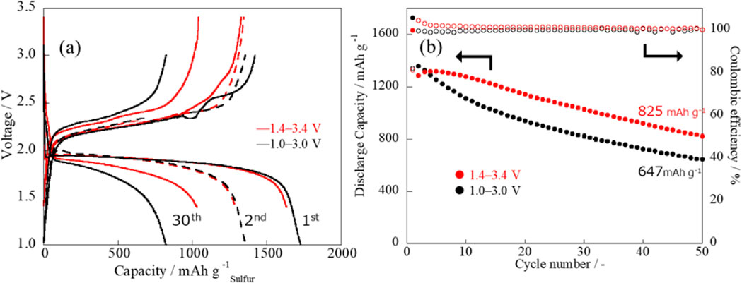
(a) Charge/discharge curves and (b) discharge capacities and efficiencies in cycling for Li-S batteries with different operating voltage ranges.
To elucidate whether changing the discharge voltage limit is effective even in the middle of charge/discharge cycling, we switched the voltage limit at the 10th cycle as shown in Fig. 6. We observed the capacity retention before and after voltage switching. A cell that had been charged and discharged in the 1.0–3.4 V range until the 10th cycle was allowed to charge and discharge in a voltage range of 1.4–3.4 V from the 11th cycle, while the reverse switching condition was also applied to another cell. To compare the capacity retention, we set the discharge capacity in the 1st cycle to 100 %, and the subsequent discharge capacities were expressed as the percentage remaining over the 1st cycle. In both cells, capacity decay during cycles in the 1.0–3.0 V range was more significant than during cycles in the 1.4–3.4 V range. Interestingly, even if the cell operation begins with cycles in the 1.0–3.4 V range and capacity decay occurs, switching to 1.4–3.4 V at the 11th cycle stabilizes capacity decay.

Discharge capacities and efficiencies in cycling with switching discharge voltage limit at 11th cycle.
The operating voltage range of Li-S batteries was optimized based on the response current obtained by CV measurements. A discharge voltage below 1.4 V, unresponsive to CV measurements, continuously reduces the cycle life of Li-S batteries. A discharge cutoff voltage of 1.4 V suppressed the capacity decay of Li-S batteries, whereas an increase in the charging voltage limit increased the expressed capacity. Such an operating voltage range is an essential factor that can control the lifetime and actual capacity of Li-S batteries and should be investigated and designed in detail depending on the electrolyte type and composition of the active cathode material.
This study was partially supported by the Advanced Low Carbon Technology Research and Development Program (ALCA) and Specially Promoted Research for Innovative Next Generation Batteries (ALCA-SPRING[JPMJAL1301]) of the Japan Science and Technology Agency (JST).
The data that support the findings of this study are openly available under the terms of the designated Creative Commons License in J-STAGE Data at https://doi.org/10.50892/data.electrochemistry.22800203.
Takeshi Tonoya: Conceptualization (Equal), Data curation (Lead), Formal analysis (Lead), Investigation (Equal), Methodology (Equal), Validation (Equal), Visualization (Lead), Writing – original draft (Lead)
Yukiko Matsui: Investigation (Equal), Methodology (Equal), Resources (Equal), Validation (Equal)
Hidenori Hinago: Conceptualization (Equal), Investigation (Equal), Methodology (Equal), Resources (Equal)
Masashi Ishikawa: Conceptualization (Equal), Funding acquisition (Lead), Methodology (Equal), Project administration (Lead), Resources (Equal), Supervision (Lead), Writing – review & editing (Lead)
The authors declare no conflict of interest in the manuscript.
Japan Science and Technology Agency: JPMJAL1301
T. Tonoya: ECSJ Student Member
Y. Matsui and H. Hinago: ECSJ Active Members
M. Ishikawa: ECSJ Fellow